Transcription
Chapter 2Refrigerated CondensersKaren SchaffnerKevin BradleyDavid RandallRTI InternationalResearch Triangle Park, NC 27709John L. SorrelsAir Economics Group, OAQPSU.S. Environmental Protection AgencyResearch Triangle Park, NC 27711November 2017
Contents2.1Introduction . 2-12.1.1 System Efficiencies and Performance . 2-12.2Process Description . 2-12.2.1 VOC Condensers . 2-32.2.2 Refrigeration Unit . 2-42.2.32.3Auxiliary Equipment . 2-5Design Procedures . 2-52.3.1 Estimating Condensation Temperature . 2-62.3.2 VOC Condenser Heat Load . 2-82.3.3 Condenser Size. 2-112.3.4 Coolant Flow Rate . 2-122.3.5 Refrigeration Capacity . 2-132.3.6 Recovered VOC . 2-132.3.7 Auxiliary Equipment . 2-132.3.8 Alternate Design Procedure . 2-142.4Estimating Total Capital Investment . 2-142.4.1 Equipment Costs for Packaged Solvent Vapor Recovery Systems . 2-152.4.2 Equipment Costs for Nonpackaged (Custom) Solvent Vapor RecoverySystems . 2-182.4.3 Equipment Costs for Gasoline Vapor Recovery Systems. 2-192.4.4 Installation Costs . 2-202.5Estimating Total Annual Cost. 2-22212.5.1 Direct Annual Costs . 2-222.5.2 Indirect Annual Costs . 2-232.5.3 Recovery Credit . 2-242.5.42.6Total Annual Cost . 2-24Example Problem 1 . 2-242.6.1 Required Information for Design . 2-242.6.2 Equipment Sizing . 2-252.6.3 Equipment Costs . 2-282.6.4 Total Annual Cost . 2-292.7Example Problem 2 . 2-312.7.1Required Information for Design . 2-31i
2.8Acknowledgements . 2-31References . 2-32Appendix A Properties of Selected Compounds . 2-34Appendix B Documentation for Gasoline Vapor Recovery System Cost Data . 2-38ii
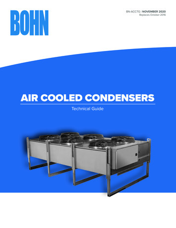
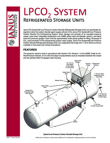
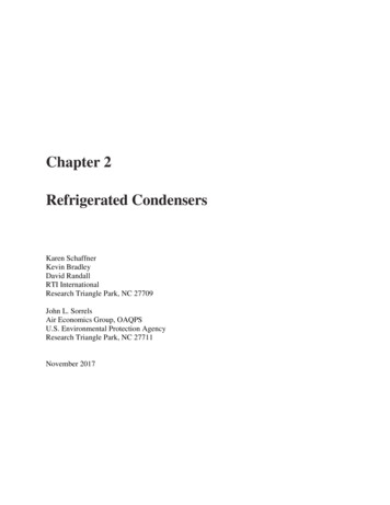
2.1IntroductionCondensers in use today may fall in either of two categories: refrigerated or nonrefrigerated. Non-refrigerated condensers are widely used as raw material, product, and/orsolvent recovery devices in chemical process industries. They are frequently used prior to controldevices (e.g., incinerators or absorbers). Refrigerated condensers are used as air pollution controldevices for treating emission streams with high VOC concentrations (usually 5,000 ppmv) inapplications involving gasoline bulk terminals, storage, etc. Condenser control technology isunique in that it not only reduces emissions to the atmosphere but also captures or recoversVOCs, potentially for additional use.Condensation is a separation technique in which one or more volatile components of avapor mixture are separated from the remaining vapors through saturation followed by a phasechange. The phase change from gas to liquid can be achieved in two ways: (a) the systempressure can be increased at a given temperature, or (b) the temperature may be lowered at aconstant pressure. In a two-component system where one of the components is noncondensible(e.g., air), condensation occurs at dew point (saturation) when the partial pressure of the volatilecompound is equal to its vapor pressure. The more volatile a compound is (e.g., the lower thenormal boiling point), the larger the amount that can remain as vapor at a given temperature;hence the lower the temperature required for saturation (condensation). Refrigeration is oftenemployed to obtain the low temperatures required for acceptable removal efficiencies. Thischapter is limited to the evaluation of refrigerated condensation at constant (atmospheric)pressure.2.1.1 System Efficiencies and PerformanceThe removal efficiency of a condenser is dependent on the emission streamcharacteristics including the nature of the VOC in question (vapor pressure/temperaturerelationship), VOC concentration, and the type of coolant used.1 Any component of any vapormixture can be condensed if brought to a low enough temperature and allowed to come toequilibrium. Figure 2.1 shows the vapor pressure dependence on temperature for selectedcompounds (Erikson, 1980). A condenser cannot lower the inlet concentration to levels belowthe saturation concentration at the coolant temperature. Removal efficiencies of approximately50 to 90 percent can be achieved with coolants such as chilled water and brine solutions, andremoval efficiencies above 90 percent can be achieved with ammonia, liquid nitrogen,chlorofluorocarbons, hydrochlorofluorocarbons, or hydrofluorocarbons, depending on the VOCcomposition and concentration level of the emission stream.2.2Process DescriptionFigure 2.2 depicts a typical configuration for a refrigerated surface condenser system asan emission control device. The basic equipment required for a refrigerated condenser systemincludes a VOC condenser, a refrigeration unit(s), and auxiliary equipment (e.g., precooler,recovery/storage tank, pump/blower, and piping).1Organic hazardous air pollutants (HAPs) are considered a subset of VOC compounds.2-1
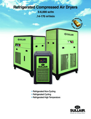
Figure 2.1: Vapor Pressures of Selected Compounds vs. Temperature (Erikson, 1980)Figure 2.2: Schematic Diagram for a Refrigerated Condenser System2-2
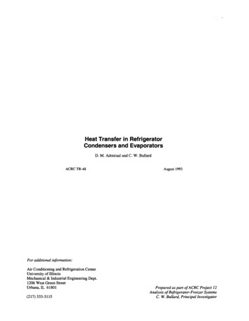
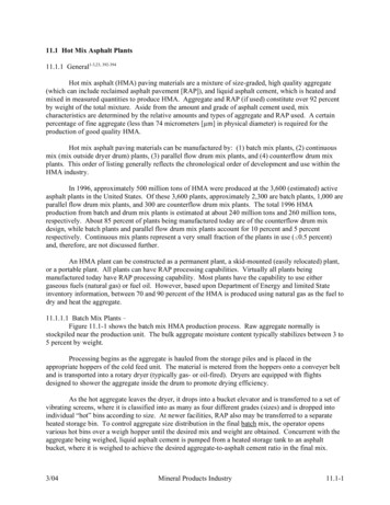
2.2.1 VOC CondensersThe two most common types of condensers used are surface and contact condensers(Vatavuk and Neveril, 1983). In surface condensers, the coolant does not contact the gas stream.Most surface condensers in refrigerated systems are the shell and tube type (see Figure 2.3)(McCabe and Smith, 1976). Shell and tube condensers circulate the coolant through tubes. TheVOCs condense on the outside of the tubes (i.e., within the shell). Plate and frame type heatexchangers are also used as condensers in refrigerated systems. In these condensers, the coolantand the vapor flow separately over thin plates. In either design, the condensed vapor forms a filmon the cooled surface and drains away to a collection tank for storage, reuse, or disposal.In contrast to surface condensers where the coolant does not contact either the vapors orthe condensate, contact condensers cool the vapor stream by spraying either a liquid at ambienttemperature or a chilled liquid directly into the gas stream.Spent coolant containing the VOCs from contact condensers usually cannot be reuseddirectly and can be a waste disposal problem. Additionally, VOCs in the spent coolant cannot bedirectly recovered without further processing. Since the coolant from surface condensers doesnot contact the vapor stream, it is not contaminated and can be recycled in a closed loop. Surfacecondensers also allow for direct recovery of VOCs from the gas stream. This chapter addressesthe design and costing of refrigerated surface condenser systems only.Figure 2.3: Schematic Diagram of a Shell and Tube Surface Condenser (McCabe and Smith, 1976)2-3
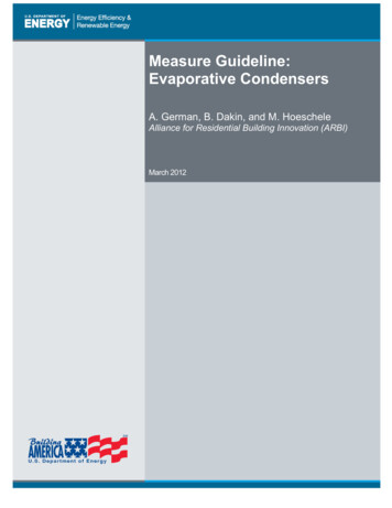
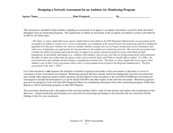
2.2.2 Refrigeration UnitThe commonly used mechanical vapor compression cycle to produce refrigerationconsists of four stages: evaporation, compression, condensation, and expansion (see Figure 2.4)(Green, 2008). The cycle that is used for single-stage vapor compression involves two pressures,high and low, to enable a continuous process to produce a cooling effect. Heat absorbed from thegas stream evaporates the liquid coolant (refrigerant). Next, the refrigerant (now in vapor phase)is compressed to a higher temperature and pressure by the system compressor. Then, thesuperheated refrigerant vapor is condensed, rejecting its sensible and latent heat in the condenser.Subsequently, the liquid refrigerant flows from the condenser through the expansion valve,where pressure and temperature are reduced to those in the evaporator, thus completing thecycle.Figure 2.4: Basic Refrigeration Cycle (Green, 2008)The capacity of a refrigeration unit is the rate at which heat is removed, expressed in tonsof refrigeration. One ton of refrigeration is the refrigeration produced by melting one ton of ice at32 F in 24 hours. It is the rate of removing heat equivalent to 12,000 British thermal units perhour (Btu/hr) or 200 Btu/min. For more details on refrigeration principles, see References Kern,1950, and Smith, VanNess, and Abbott, 2005.For applications requiring low temperatures (below about -30 F), multistage refrigerationsystems are frequently employed (Green, 2008). Multistage systems are designed and marketedin two different types―compound and cascade. In compound systems, only one refrigerant isused. In a cascade system, two or more separate refrigeration systems are interconnected in sucha manner that one provides a means of heat rejection for the other. Cascade systems are desirablefor applications requiring temperatures between -50 and -150 F and allow the use of differentrefrigerants in each cycle (Green, 2008). Theoretically, any number of cascaded stages arepossible, each stage requiring an additional condenser and an additional stage of compression.In refrigerated condenser systems, two kinds of refrigerants are used, primary andsecondary. Primary refrigerants are those that undergo a phase change from liquid to gas afterabsorbing heat. Examples are ammonia (R-717), liquid nitrogen (R-728), chlorofluorocarbons,hydrochlorofluorocarbons such as chlorodifluoromethane (R-22), or hydrofluorocarbons such as2-4
R-410A or 1,1,1,2-Tetrafluoroethane (R-134a). Concerns about CFCs and HCFCs causingdepletion of the ozone layer prompted development of HFCs, and recent concerns about HFCsbeing potent greenhouse gases are further prompting development of systems using alternaterefrigerants (EPA, 2001, and EPA, 2015).Secondary refrigerants such as brine solutions act only as heat carriers and remain inliquid phase. Conventional systems use a closed primary refrigerant loop that cools thesecondary loop through the heat transfer medium in the evaporator. The secondary heat transferfluid is then pumped to a VOC vapor condenser where it is used to cool the air/VOC vaporstream. In some applications, however, the primary refrigeration fluid is directly used to cool thevapor stream.2.2.3 Auxiliary EquipmentAs shown in Figure 2.2, some applications may require auxiliary equipment such asprecoolers, recovery/storage tanks, pumps/blowers, and piping.If water vapor is present in the treated gas stream or if the VOC has a high freezing point(e.g., benzene), ice or frozen hydrocarbons may form on the condenser tubes or plates. This willreduce the heat transfer efficiency of the condenser and thereby reduce the removal efficiency.Formation of ice will also increase the pressure drop across the condenser. In such cases, aprecooler may be needed to condense the moisture prior to the VOC condenser. This precoolerwould bring the temperature of the stream down to approximately 35 to 40 F, effectivelyremoving the moisture from the gas. Alternatively, an intermittent heating cycle can be used tomelt away ice build-up. This may be accomplished by circulating ambient temperature brinethrough the condenser or by the use of radiant heating coils. If a system is not operatedcontinuously, the ice can also be removed by circulating ambient air.A VOC recovery tank for temporary storage of condensed VOC prior to reuse,reprocessing, or transfer to a larger storage tank may be necessary in some cases. Pumps andblowers are typically used to transfer liquid (e.g., coolant or recovered VOC) and gas streams,respectively, within the system.2.3Design ProceduresIn this section, two procedures are presented for designing (sizing) refrigerated surfacecondenser systems to remove VOC from air/VOC mixtures. With the first procedure presented,one calculates the condenser exit temperature needed to obtain a given VOC recovery efficiency.In the second procedure, which is the inverse of the first, the exit temperature is given and therecovery efficiency corresponding to it is calculated.The first procedure depends on knowledge of the following parameters:1. Volumetric flow rate of the VOC-containing gas stream;2. Inlet temperature of the gas stream;3. Concentration and composition of the VOC in the gas stream;2-5
4. Required removal efficiency of the VOC;5. Moisture content of the emission stream; and6. Properties of the VOC (assuming the VOC is a pure compound): Heat of condensation,Heat capacity, andVapor pressure.The design of a refrigerated condenser system requires determination of the VOCcondenser size and the capacity of the refrigeration unit. For a given VOC removal efficiency,the condensation temperature and the heat load need to be calculated to determine theseparameters. The data necessary to perform the sizing procedures as well as the variable namesand their respective units are listed in Table 2.1.Table 2.1: Required Input DataDataInlet Stream Flow RateInlet Stream TemperatureVOC Inlet Volume FractionRequired VOC Removal EfficiencyAntoine Equation ConstantsaHeat of Condensation of the VOCaHeat Capacity of the VOCaSpecific Heat of the CoolantHeat Capacity of AirVariable NameQinTinyVOC,inηA, B, C HCp,VOCCp,coolCp,airUnitsscfm (at 77 F; 1 atm) FVolume fractionFractional (volume)―Btu/lb-moleBtu/lb-mole- FBtu/lb- FBtu/lb-mole- FaSee Appendix A for these properties of selected organic compounds.The steps outlined below for estimating condensation temperature and the heat load applyto a two-component mixture (VOC/air) in which one of the two components is considered to benoncondensible (air). The VOC component is assumed to consist of a single compound. Also,the emission stream is assumed to be free of moisture. The calculations are based on theassumptions of ideal gas and ideal solution to simplify the sizing procedures. For a more rigorousanalysis, see Reference Kern, 1950.2.3.1 Estimating Condensation TemperatureThe temperature necessary to condense the required amount of VOC must be estimated todetermine the heat load. The first step is to determine the VOC concentration at the outlet of thecondenser for a given removal efficiency. This is calculated by first determining the partialpressure of the VOC at the outlet, PVOC. Assuming that the ideal gas law applies, PVOC is givenby:2-6
PVOC 760 M VOC ,outM in M VOC , recovered(2.1)where:PVOC partial pressure of the VOC in the exit stream (mm Hg)Min moles in the inlet stream (moles per hour, moles/hr)MVOC,out moles of VOC in the outlet stream (moles/hr)MVOC,recovered moles of VOC condensed, or recovered (moles/hr)The condenser is assumed to operate at a constant pressure of one atmosphere (760 mm Hg).However:M VOC,out M VOC , in 1 (2.2)where:MVOC,in moles of VOC in the inlet stream (moles/hr)η removal efficiency of the condenser system (fractional)andM VOC , in M in yVOC,in(2.3)where:yVOC,in volume fraction of VOC in inlet stream.The removal efficiency, η, can also be defined as “moles VOC recovered / moles VOC in inlet:” moles VOC recoveredmoles VOC in inletor: M VOC ,re cov eredM VOC ,in(2. 4)Rearranging Equation 2.4, we obtain:M VOC ,re cov ered M VOC ,in After substituting these variables in Equation 2.1, we obtain:2-7(2.5)
yVOC,in 1 PVOC 760 1 yVOC,in (2.6)At the condenser outlet, the VOC in the gas stream is assumed to be at equilibrium withthe VOC condensate. At equilibrium, the partial pressure of the VOC in the gas stream is equalto its vapor pressure at that temperature assuming the condensate is pure VOC (i.e., vaporpressure PVOC). Therefore, by determining the temperature at which this condition occurs, thecondensation temperature can be specified. This calculation is based on the Antoine equation thatdefines the relationship between vapor pressure and temperature for a particular compound:log 10 PVOC A BTcon C(2.7)where:Tcon condensation temperature (degrees Celsius, or C)A, B, C VOC-specific constants pertaining to temperature expressed in C and pressurein millimeters of mercury (mm Hg) (see Appendix A, Table A-2)Rearranging and solving for Tcon in degrees Fahrenheit (ºF): BTcon C 1 .8 32 A log 10 ( PVOC ) (2.8)The calculation methods for a gas stream containing multiple VOCs are complex,particularly when there are significant departures from the ideal behavior of gases and liquids.However, the temperature necessary for condensation of a mixture of VOCs can be estimated bythe weighted average of the temperatures necessary to condense each VOC in the gas stream at aconcentration equal to the total VOC concentration (Erikson, 1980).2.3.2 VOC Condenser Heat LoadCondenser heat load is the amount of heat that must be removed from the inlet stream toattain the specified removal efficiency. It is determined from an energy balance, taking intoaccount the enthalpy change due to the temperature change of the VOC, the enthalpy change dueto the condensation of the VOC, and the enthalpy change due to the temperature change of theair. Enthalpy change due to the presence of moisture in the inlet gas stream is neglected in thefollowing analysis.For the purpose of this estimation, it is assumed that the total heat load on the system isequal to the VOC condenser heat load. Realistically, w
The commonly used mechanical vapor compression cycle to produce refrigeration consists of four stages: evaporation, compression, condensation, and expansion (see Figure 2.4) (Green, 2008). The cycle that is used for single-stage vapor compression involves two pressures, high and low, to