Transcription
TND6312/DRev. 2, November 20198x8 Home Gateway BenefitsOriginally published in May. 2018 under the company name Quantenna Communications, Inc. Semiconductor Components Industries, LLC, 2018November, 2019 Rev. 21Publication Order Number:TND6312/D
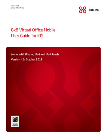
8x8 Home Gateway BenefitsIntroductionData usage and media consumption habits within a home have dramatically changed inrecent times. The proliferation of over the top (OTT) streaming services and increasedpenetration of mobile devices with high resolution displays have resulted in viewing habits thatare personalized to each user rather than an entire family. This in turn has increasedthe minimum aggregate Wi Fi data rate need to multi hundreds of Mbps. Furthermore, thesedevices can be located anywhere within the home and hence it is paramount to ensure wholehome coverage.Within homes, Multi input Multi output (MIMO) Wi Fi gateways and clients have beendeployed for nearly a decade starting with the 802.11n standard. It is well known that a wirelessMIMO system can improve the data rate of single user using multiple antennas for transmissionand reception. This is done by spatially multiplexing the data onto a number of parallel streams,transmitting them simultaneously in the same frequency band, and separating themat the receiver using multiple antennas. In general, given a sufficiently multi path richpropagation medium, a communication system consisting of a Wi Fi device with M transmittersand another Wi Fi device with N receivers can achieve a data rate increase that is linearlyproportional to min (M, N). If M N, additional performance benefit can be obtained in the formof transmit beamforming and if N M, then the excess receivers can be used to provide receivediversity gain. Figure 1 shows the Shannon capacity for various MIMO configurations whenM N (i.e. the channel from each transmitter to the receiver is independently and identicallydistributed complex Gaussian random variables with zero mean and unit variance). At highsignal to noise ratios, it is seen that the capacity grows linearly with the number of antennas.www.onsemi.com2
Figure 1. Shannon Capacity of an NxN MIMO SystemWhile the initial deployments of Wi Fi with MIMO capability focused on a single user, it hasbecome apparent that these data rate gains in real life are not scaling as expected. This isbecause most client devices, especially mobile, have at most 2 transmitters and/or receiverslimiting the spatial multiplexing gain to at most 2. However, the advent and rapid adoption of socalled multi user MIMO (MU MIMO) Wi Fi promises to leverage the benefits of MIMO tomultiple devices simultaneously. In multi user MIMO, if a gateway has M transmitters, it cantransmit simultaneously to K clients, each equipped with N1, N2, N3, , Nk receivers, as longas N1 N2 Nk does not exceed M on the downlink. Similarly, in the uplink multi user MIMOcase, K client devices each equipped with M1, M2, M3, Mk transmitters can transmit toa gateway with N receivers as long as M1 M2 M3 Mk is at most equal to N. Thus MU MIMOis needed to exploit the MIMO capability at a home gateway to the fullest extent. In this whitepaper, we will focus on the benefits of higher order MIMO when MU MIMO is utilized.Current home gateways are being deployed with 4 transmitters and 4 receivers (4x4 MIMOhome gateway). In order to improve overall home coverage, repeaters and/or multiple Wi Finodes that are capable of networking with each other are subsequently added. However, useof repeaters often come at the cost of lowering the network capacity because of the half duplexnature of the repeaters.www.onsemi.com3
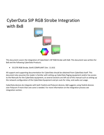
A better solution is to have home gateways support 8x8 MU MIMO. This allows support ofmultiple MU MIMO clients within the home while providing improved coverage and highernetwork capacity. This 8x8 system is shown to offer the following key benefits over a 4x4 systemfor a typical home using simulation models and real life measured data in the following manner: Single User Data Rate – An 8x8 AP can outperform a 4x4 AP in its single user throughput.Overall throughput is significantly improved within a 3000 sq. ft. home, resulting in an averageof at least 60% improvement in the achievable throughput. About 24% of a 3000 sq. ft. homeshows more than 100% improvement. Home Coverage – An 8x8 AP has a larger coverage area than its 4x4 counterpart. Givena minimum bit rate of 100 Mbps, 35% more homes would require a repeater with 4x4 APdeployment compared to 8x8 AP deployment. MU MIMO – An 8x8 AP has significantly better MU MIMO performance and unparalleledscaling with group size. MU MIMO gains scale up to 4 clients for 8x8 but caps at 2 clients for4x4 deployments. Repeater Configuration Minimizing the need for repeater/mesh within a home over 4x4thus providing the most economical deployment for service providers within the home.The next two sections describe the simulation model and summarize the simulation resultsshowing the performance comparison between 8x8 and 4x4 APs in terms of coverage, speedtest throughput and network capacity with and without repeaters. The last section describesa real life test for MU MIMO performance using a real network in a test house.Simulator DescriptionA Quantenna simulator was used to model Wi Fi network behavior in a typical home withaccess points (AP) and Repeaters. Network behavior includes the coverage and speed testrates supported in the home, link budget analysis, airtime distribution and network capacitycalculation for a given set of AP, Repeater, and Stations (STA) in a home. The simulator isimplemented using Matlab and models the network at a flow level using medium access (MAC)and physical (PHY) layer models. The input output model is shown in Figure 2 and describedbelow.Floorplan,AP/Rep/STA locationsAP/Rep/STA configurationsSTA data rateQTN MACSimulatorCoverageP2P RatePMP RateFigure 2. Input Output Model of the MAC Simulatorwww.onsemi.com4
Input VariablesThe input to the simulator is a floorplan with the location of the AP, repeaters (if present)and the stations. The floorplan is described in terms of the internal and external walls.The location of the AP is constrained to be near an external wall, with an assumption thatthe broadband connection entry point is located there. The location of the repeaters isconstrained to be near any wall. The STAs are located based on typical use cases in homes.The MIMO configuration of the AP/Repeater/STAs, band (2.4G or 5G), BW (20, 40, 80,160 MHz) of the links between the AP Repeater, Repeater STA, AP STA and the requireddata rate for each STA are configurable. In addition, the mode of operation: full duplex (FD) orhalf duplex (HD) and single user (SU) or multi user (MU) operation is configurable forthe AP Repeater link.Output MetricsThe simulator calculates the point to point (P2P) or point to multi point (PMP) UDPdownlink (DL) rate supported by each link specified. For a P2P calculation, usually a grid ofevenly distributed STAs all over the floorplan is used. The simulator can also calculate the PMPrate supported by a specified set of STAs. The location of the AP/repeaters can be foundautomatically (best location dependent on a metric, e.g. coverage or average P2P rate etc.) orcan be fixed (the results in the later sections uses fixed locations). During the P2P and PMPsimulations, the model also indicates the STAs or regions in the floorplan that are not coveredby the current AP/Repeater combination.Simulation ProcedureThe simulation procedure is outlined in Figure 3. The path loss is calculated using the IEEE802.11ax model. All walls in the home are assumed to have the same construction so as to havethe same attenuation for Wi Fi signals. From the location of the transmitter (TX) and receiver(RX), the path loss of the link is calculated, which is a function of the distance betweenthe endpoints, number of walls and floors that the path crosses. The RSSI is also calculatedfrom the AP and different available repeaters to decide how is the STA connected to the AP(directly or through a repeater). The STA decides on which AP or Repeater to associate basedon the best RSSI.This behavior emulates simple association logic where the AP and Repeaters share the SSID.The clients are assumed to be stationary and once connected to a Repeater or AP, the routingof the packets is fixed for the duration of the traffic. If the RSSI is too low to support even MCS0,the STA is said to be disconnected. Then, experimental range vs rate (RvR) data is used toconvert the path loss to a physical layer rate that the link can support. At this point for P2P ratecalculation, timing calculation is done for packet aggregation and overhead for various UDP, IP,MAC and PHY headers including the modifications for single or multi hop links. For a linkthrough a repeater, the repeater buffer size is configurable to allow for delays due to scheduling.www.onsemi.com5
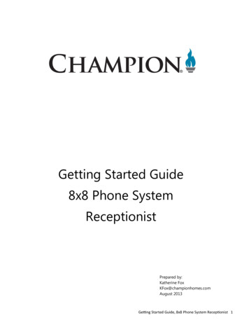
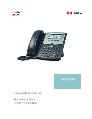
For PMP rate calculation, depending on the required data rate for the STAs, the airtime requiredis first calculated and then the flows are scheduled based on the fairness criteria. Airtimefairness is used for the results shown later.Figure 3. Steps Involved in the MAC SimulatorSimulation of Network GainsFrom the results of simulations done over different floorplans varying in size from 2000 sq. ft.to 4000 sq. ft. the main conclusion is that, an 8x8 AP offers significantly improved performancefor many different metrics (coverage, speed test performance, network performance, airtimeusage, and scalability etc.).Repeater Requirements for Typical HomesThe experimental RvR indicates that there is around a 5 6 dB gain for using an 8x8 AP ascompared to a 4x4 AP in the linear region of the curve (approximately in the 75–110 dB pathloss range) as shown in Figure 4. This suggests that any link in the home in this range ofpath loss will get a boost of 5 6 dBs in performance by switching to an 8x8 AP. As example,Figure 4 shows 5 dB of pathloss difference between 8x8 and 4x4 Aps for a 100 Mbpsconnection to a 2x2 STA.www.onsemi.com6
Figure 4. Typical RvR for a 2x2 STAWe have obtained real life path loss from 7000 actual homes using Quantenna MAUI cloudplatform and the data collected is shown in Figure 5. This data shows the path loss on the Y axisand the percentage of the total number 7000 homes that have a specific path loss. This datawhen combined with Figure 4 suggests that to support a rate of 100 Mbps within the home,about 45% of the 4x4 homes will be able to sustain this speed whereas, 85% of the 8x8 homescan support this speed. This means less repeaters need to be provisioned for homes with 8x8APs.Figure 5. Pathloss Distribution (90%) Based on 7000 Homes. Additional5 dB of Serviceable Area for 8x8 AP as Compared to 4x4 Highlightedwww.onsemi.com7
Single AP Coverage and Rate GainsAnother way to examine the advantages of 8x8 AP over 4x4 AP is to perform a single APcoverage simulation. As an example, the floorplan of Figure 6 is used. The location of the APis show by a red star. The location of the AP is kept near an outer wall in the garage to emulatea real life scenario. Due to the size of the house, about 23% of the home is disconnected whena 4x4 AP is used, however only about 9% of the home is disconnected when an 8x8 AP is used.The coverage simulation is done using a grid of finely spaced STAs all over the house. A finegrid of points is overlaid on the entire floorplan. Each grid point is taken as a possible locationof a station. The per link RSSI is calculated and if the RSSI is enough to support the lowestMCS, the point is tagged as covered by the AP or AP repeater group, and tagged asdisconnected otherwise. The proportion of coverage area is the ratio of connected grid pointsto total points in the grid. For the 4000 sqft floor plan shown in Figure 6, approximately 840,000grid points were used.Figure 6. Floorplan of Size 4012 sqft with the AP Shownas a Red Star and the STAs Shown with Blue CirclesIn addition to coverage, there is a sizeable speed gain, as shown in Figure 7. On the x axis,we are showing the gain in the achievable rate when we switch from a 4x4 AP to an 8x8 AP.The y axis shows what percentage of the floorplan gets such a gain. About 14% of the housethat was previously left uncovered by the 4x4 AP can be covered by the 8x8 AP. Additionally,about 24% of the home gets more than 100% gain in the achievable speed test rate (P2P) whenwe switch to an 8x8 AP.www.onsemi.com8
Figure 7. Rate Gain of 8x8 AP as Compared with a 4x4 APSingle User and Multi User Gains with RepeatersFor doing the network capacity calculation, we use a network with three 1x1 STAs each usinga 20 Mbps link, three 2x2 STAs each using a 40 Mbps link and two 4x4 STAs each using100 Mbps links. For such a network setup, we calculate the network throughput supported bythe 4x4 and 8x8 APs, when used in conjunction with one or two 2x2 repeaters. In this scenario,the network is used in a half duplex mode (only one link active at the same time). Allthe simulation uses downlink traffic. For calculating a single link’s capacity, first the traffic routingis calculated. In case of a multi hop link, the max rate supported is calculated (based onthe RSSI and MIMO order supported by the link) in each link and the achievable rate iscalculated as the harmonic mean of the rates of each hop. For calculating the sum throughput,airtime is scheduled between all the links (that interfere with each other) using an airtimefairness scheduler at the AP and repeaters (since all traffic is downstream). Using the availableairtime and the supported rate, the achieved data rate is calculated for each link. The networkcapacity is estimated as the sum of the achieved data rate for all the STAs. The network ratecomparison is shown in Figure 8. For the 8x8 AP, when there are two repeaters available,the AP Repeater link can also use MU MIMO which can not only increase the networkcapacity, but perform better than just having an AP.www.onsemi.com9
Figure 8. Network Rate Comparison with 8 STAsIn fact, it is noticeable that when a 4x4 AP is used, the loss in the network throughput is lotmore than when an 8x8 AP is used. The loss is attributed to the lost airtime by the STAs dueto the new AP Repeater link. However, for the 8x8 AP, due to the better supported rate,the airtime loss is less as compare to the 4x4 AP. The degradation in rates due to addingrepeaters is summarized in Figure 9.Figure 9. Degradations in Rate Due to Adding Half Duplex RepeatersIn summary, the 8x8 AP expands the network coverage, which can result in a lower cost sincemost of the homes won’t need a repeater. In the cases when a repeater is needed for coveragereasons, the 8x8 AP will be able to scale better in terms of network capacity and if the repeatersare MU MIMO compatible, the setup will result in a higher overall system capacity.www.onsemi.com10
Experimental MU MIMO ResultsIn addition to network simulations, extensive real life performance studies have beenconducted inside a test house. In this section, we summarize the MU MIMO benefits of onesuch study for an 8x8 AP over 4x4 AP. In recent years, a large number of clients with MU MIMOcapability has been deployed and these include the Samsung Galaxy S8, Google Pixel 1 and 2,Moto Z force, Microsoft Lumia 950, Laptops with Intel 8265 chipsets, and many others.For the purpose of this study, we used an Acer laptop as the client which has the QualcommQCA9377 (1x1) chipset. The APs used were based on Quantenna’s QSR1000 4x4and QSR10G 8x8 Wi Fi chipsets. The clients were distributed at 4 different fixed locations, twoof them close to the AP with good RSSI, one mid range and one farther away as shownin Figure 10.Figure 10. Floorplan with Locations of the AP and the Four MU Capable ClientsThroughput tests were done using all possible combinations of STAs to form MU groups ofsize 2, 3, and 4 STAs. Measured results are shown in Table 1. The average value for each MUgroup size is highlighted in the table. With two active clients, the aggregate TCP data ratereached was about 450 Mbps with 4x4 system while the 8x8 system achieves about 600 Mbpswhich is a 35% improvement. With three active clients, the 4x4 system’s throughput decreasedslightly to 425 Mbps approximately while the 8x8 system achieves nearly 800 Mbps resultingin an 80% improvement. The limitations of 4x4 MU MIMO is clearly obvious with the systemunable to scale gains. With all clients active, the TCP throughput for the 4x4 system drops toabout 385 Mbps while the 8x8 system’s throughput is about 850 Mbps resulting in more than2x gain.www.onsemi.com11
Table 1. UDP AND TCP RATES fOR DIFFERENT MU CONFIGURATIONS USING THEACER 1X1 CLIENT WITH QSR1000 4X4 AP AND QSR10G 8X8 APGroupingACER Laptop QCA9377 (1x1)1 11 1 11 1 1 1QSR1000 (4x4)QSR 10G (8x8)UDPTCPUDPTCP(L301, L302)524446622618(L301. L304)530452625558(L301, L308)535466631626(L302, L304)532473620623(L302, L308)504447618612(L304, L308)445390627625AVG512446624610(L301, L302, L304)364459826789(L301, L302, L308)389447821782(L302, L304, L308)387422845829(L301, L304, L308)364450824803AVG376444829801(L301, L302, L304, L308)360385905842NOTE: All rates are in Mbps in the last four columns. The second column refers to the location of the STAs asshown in Figure 10.The throughput drop of the 4x4 system with increasing number of clients is due to the needto serve clients farther away resulting in a lower overall throughput. The 8x8 AP not onlyoutperforms the 4x4 version, but scales much better for larger MU group sizes.ConclusionTo summarize, the deployment of 8x8 APs significantly increases the data rate over 4x4 APdeployments. Data rate improvements of more than 60% were achieved for houses of3000 sq. ft. and above, with nearly 24% of the simulated home seeing at least 2x data rateimprovements. Additionally, disconnects go down from nearly 23% for a 4x4 deployment tobelow 10% for 8x8 deployment resulting in 60% decrease in disconnects. It is also shown thatMU MIMO scales better with 8x8 as compared to 4x4. While coverage can be improved byadding repeaters, network capacity goes down due to the half duplex nature of repeatersresulting in lower capacity as compared to using 8x8 AP in those homes where 8x8 AP providesadequate coverage.www.onsemi.com12
Wi Fi is a registered trademark of the Wi Fi AllianceQuantenna is a registered trademark of Semiconductor Components Industries, LLC (SCILLC) or its subsidiaries in the United Statesand/or other countriesAll brand names and product names appearing in this document are registered trademarks or trademarks of their respective holders.ON Semiconductor andare trademarks of Semiconductor Components Industries, LLC dba ON Semiconductor or its subsidiaries in the United States and/or other countries.ON Semiconductor owns the rights to a number of patents, trademarks, copyrights, trade secrets, and other intellectual property. A listing of ON Semiconductor’s product/patentcoverage may be accessed at www.onsemi.com/site/pdf/Patent Marking.pdf. ON Semiconductor reserves the right to make changes without further notice to any products herein.ON Semiconductor makes no warranty, representation or guarantee regarding the suitability of its products for any particular purpose, nor does ON Semiconductor assume any liabilityarising out of the application or use of any product or circuit, and specifically disclaims any and all liability, including without limitation special, consequential or incidental damages.Buyer is responsible for its products and applications using ON Semiconductor products, including compliance with all laws, regulations and safety requirements or standards,regardless of any support or applications information provided by ON Semiconductor. “Typical” parameters which may be provided in ON Semiconductor data sheets and/orspecifications can and do vary in different applications and actual p
to 4000 sq. ft. the main conclusion is that, an 8x8 AP offers significantly improved performance for many different metrics (coverage, speed test performance, network performance, airtime usage, and scalability etc.). Repeater Requirements for Typical Homes The experimental RvR indicates