Transcription
MAKING MODERN LIVING POSSIBLEElectrically operated suctionmodulating control valves,type KVSREFRIGERATION &AIR CONDITIONING DIVISIONTechnical leaflet
Technical leafletElectrically operated suction modulating control valves, type KVSContentsPageIntroduction . . . . . . . . . . . . . . . . . . . . . . . . . . . . . . . . . . . . . . . . . . . . . . . . . . . . . . . . . . . . . . . . . . . . . . . . . . . . . . . . . . . . . . . 3Features . . . . . . . . . . . . . . . . . . . . . . . . . . . . . . . . . . . . . . . . . . . . . . . . . . . . . . . . . . . . . . . . . . . . . . . . . . . . . . . . . . . . . . . . . . . 3Technical data . . . . . . . . . . . . . . . . . . . . . . . . . . . . . . . . . . . . . . . . . . . . . . . . . . . . . . . . . . . . . . . . . . . . . . . . . . . . . . . . . . . . . 3Electrical data . . . . . . . . . . . . . . . . . . . . . . . . . . . . . . . . . . . . . . . . . . . . . . . . . . . . . . . . . . . . . . . . . . . . . . . . . . . . . . . . . . . . . . 4Design . . . . . . . . . . . . . . . . . . . . . . . . . . . . . . . . . . . . . . . . . . . . . . . . . . . . . . . . . . . . . . . . . . . . . . . . . . . . . . . . . . . . . . . . . . . . . 4Valve operation . . . . . . . . . . . . . . . . . . . . . . . . . . . . . . . . . . . . . . . . . . . . . . . . . . . . . . . . . . . . . . . . . . . . . . . . . . . . . . . . . . . . 5Sizing . . . . . . . . . . . . . . . . . . . . . . . . . . . . . . . . . . . . . . . . . . . . . . . . . . . . . . . . . . . . . . . . . . . . . . . . . . . . . . . . . . . . . . . . . . . . . . 6Valve selection . . . . . . . . . . . . . . . . . . . . . . . . . . . . . . . . . . . . . . . . . . . . . . . . . . . . . . . . . . . . . . . . . . . . . . . . . . . . . . . . . . . . . 6Ordering . . . . . . . . . . . . . . . . . . . . . . . . . . . . . . . . . . . . . . . . . . . . . . . . . . . . . . . . . . . . . . . . . . . . . . . . . . . . . . . . . . . . . . . . . . . 7Capacities . . . . . . . . . . . . . . . . . . . . . . . . . . . . . . . . . . . . . . . . . . . . . . . . . . . . . . . . . . . . . . . . . . . . . . . . . . . . . . . . . . . . . . . . . . 8Dimensions and weights . . . . . . . . . . . . . . . . . . . . . . . . . . . . . . . . . . . . . . . . . . . . . . . . . . . . . . . . . . . . . . . . . . . . . . . . . . 10 DKRCC.PD.VC1.A1.22 / RD4JE602 Danfoss A/S, (USCO/MR), 02-2007
Technical leafletElectrically operated suction modulating control valves, type KVSIntroductionKVS is a series of electrically operated suctionmodulating control valves for AC transport andrefrigeration applications.The balanced design provides bi-flow operationas well as solenoid shut-off function in both flowdirections at MOPD 33 bar (478 psi).Accurate temperature or pressure control isobtained by modulating the refrigerant flow inthe evaporator with a current or voltage driver.The KVS design is being registered. The pendingreference number is 200530003728.1.With an EKC 368 controller (current driver) and anAKS sensor placed in the media to be controlled,an accuracy better than 0.5K can be obtained.FeaturesTechnical data Danfoss A/S, (USCO/MR), 02-2007For manual operation and service of KVSvalves an AST-g service driver is available.For further information please contact Danfoss(Commercial Refrigeration & Air ConditioningControls).Balanced port design.High resolution for precise control.Solenoid tight shut-off.Low power consumption.Corrosion resistant design external as well asinternal.ParameterKVS 42-54CompatibilityHFC, HCFCCE markingYesMOPD33 bar (478 psi)Max. working pressure34 bar (493 psig)Refrigerant temperature range–40 to 10 C (–40 to 50 F)Ambient temperature–40 to 60 C (–40 to 140 F)Total stroke17.2 mm (0.68 in.)Motor enclosureIP 67DKRCC.PD.VC1.A1.22 / RD4JE602
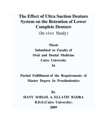
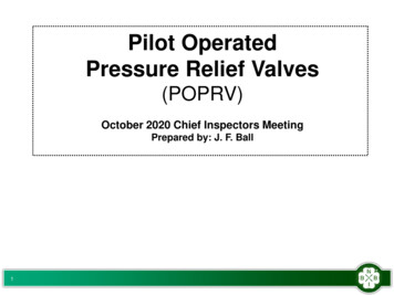
Technical leafletElectrical dataElectrically operated suction modulating control valves, type KVSParameterKVS 42-54Stepper motor typeBi-polar - permanent magnetStep mode2 phase full stepPhase resistance52Ω 10%Phase inductance85 mHHolding currentDepends on application.Full current allowed (100% duty cycle)Step angle7.5 (motor),0.9 (lead screw),Gearing ration 8.5:1. (38/13)2:1Nominal voltage(Constant voltage drive) 12 V dc -4% 15%, 150 steps/sec.Phase current(Using chopper drive) 100 mA RMS -4% 15%,Max. total powerVoltage / current drive: 5.5 / 1.3 W (UL: NEC class 2)Step rate150 steps/sec. (constant voltage drive)0-300 steps/sec. 300 recommended (chopper current drive)Total stepsKVS 42-54: 3810 [ 160 / -0] stepsFull travel timeKVS 42-54: 25.4 / 12.7 sec. (voltage / current)Lifting heightKVS 42-54: 17.2 mm (0.68 in.)Reference positionOverdriving against the full close positionElectrical connection4 wire 0.5 mm2 (0.02 in2), 2 m (6.5 ft) long cableStepper motor switch sequence:STEP CLOSING KVS 42-54Coil ICoil IIRedGreenWhite1 - Black-2 -- 3- - 4- -1 - - OPENING KVS 42-54DesignValve / Actuator type KVS / AST1.2.3.4.5.6.7.8.9.10. CableGlass sealAST motor housingStepper motorBearingSpindleInsertValve pistonValve seatValve portDKRCC.PD.VC1.A1.22 / RD4JE602 Danfoss A/S, (USCO/MR), 02-2007
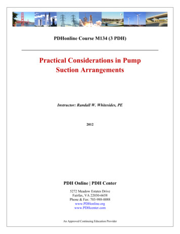
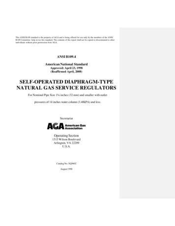
Technical leafletElectrically operated suction modulating control valves, type KVSValve operationEKC 368AKSKVSKVS valves are modulated by an electronicallycontrolled 2-phase bipolar stepper motor (AST). Thestepper stays in position unless power pulses from adriver initiate one of the two discrete sets of motorwindings that operate respectively in the opening andclosing directions.The direction of motor rotation depends on the phaserelationship of the power pulses. The distance traveleddepends on the number of pulses transmitted for agiven move.The motor drives a lead screw, whose rotating motion istransformed into linear motion by a transmission in thecage assembly.The valve cone is an exponential V-port designthat provides best part load efficiency with zeroresistance maximum capacityThe cage and orifice design is fully powerbalanced, so that bi-flow operation has equalperformance and capacity in either direction.The port design includes a shut-off function with“solenoid tightness” in both flow directions.Closed position is also the mechanical stop actingas reference point to reset the controller. The zeroreference point is reset at each closing, withaccuracy ensured by a slight overdrive.The AST motor housing has a glass sealed 2 m (6.5 feet)cable connection as standard. Cable length andconnections can be customized. Danfoss A/S, (USCO/MR), 02-2007DKRCC.PD.VC1.A1.22 / RD4JE602
Technical leafletElectrically operated suction modulating control valves, type KVSSizingFor optimum performance, it is important totake into consideration all system conditions andrequirements. Selection is also dependent on anacceptable pressure drop across the valve. Thefollowing information will be needed when sizinga KVS valve:Refrigerant - HCFC or HFCEvaporator capacity Qe in kW or TREvaporating temperature te in C or FLiquid temperature ahead of expansion valvetl in C or FMax. acceptable pressure drop in the KVSvalve in bar or psigConnection sizeValve selectionExampleIn valve selection it may be necessary to applya correction factor to the actual evaporatorcapacity. This correction is required when systemconditions are different than table conditions.Selection also depends on having an acceptablepressure drop across the valve. The followingexample illustrates correct sizing.Refrigerant:R22Evaporator capacity:Qe 20 kW (5.7 TR)Evaporating temperature:te –5 C 3.3 bar (23 F 47.9 psig)Liquid temperature ahead of expansion valve:t l 25 C (77 F)Max. pressure drop in the valve p 0.2 bar (2.9 psig)Connection type:SolderConnection size:11/8 in.Step 1Determine the correction factor for liquidtemperature t l ahead of expansion valve.From the correction factors table (see below)a liquid temperature of 25 C (100 F), R22corresponds to a factor of 1.0.Correction factors for liquid temperature tltl 4A / 13tl 920.961.01.051.10R404A / 850.890.941.01.071.15Step 2Corrected evaporator capacity isQe 20 1.0 20 kW (5.7 1.0 5.7 TR)Step 3Now select the appropriate capacity table, R22,and choose the column for an evaporatingtemperature of te –5 C (23 F).Using the corrected evaporator capacity, selecta valve that provides an equivalent or greatercapacity at an acceptable pressure drop acrossthe valve of 0.2 bar (2.9 psig).Step 4KVS 42, 11/8 in. solder connection:code no. 034L2050 DKRCC.PD.VC1.A1.22 / RD4JE602KVS 42 delivers 44.67 kW (12.8 TR) at a 0.2 bar (2.9psig) pressure drop across the valve.Based on the required connection size of 11/8in., the KVS 42 is the proper selection for thisexample. Danfoss A/S, (USCO/MR), 02-2007
Technical leafletElectrically operated suction modulating control valves, type KVSOrderingValve / Actuator type KVS / AST-g in single packRated capacity1)TypeKVS 42KVS 54R134aR22Valve KVS Actuator ASTR404A/R507ConnectionkWTRkWTRkWTRmmin.Code no.single .38.335.310.02811 .513.751 /8034G305055.515.740.311.448.513.721/8034G305154) Rated capacity is the valve capacity atevaporating temperature te –10 C (14 F),condensing temperature tc 25 C (77 F) andpressure drop across valve p 0.2 bar (2.9 psig).1 Danfoss A/S, (USCO/MR), 02-2007DKRCC.PD.VC1.A1.22 / RD4JE602
Technical leafletElectrically operated suction modulating control valves, type KVSSI unitsCapacitiesRange –40 C to 10 CRated capacity [kW]KVS 42teKVS 54Pressure drop p [bar][ C]R134aR404A/R507R22Correction 0.9798.12123.95143.41tl [ C] 25 30 35 40R134a, R221.01.041.091.14R404a/R5071.01.061.121.20The values in the capacity table refer to theevaporator capacity and are based on liquidtemperature t l 25 C ahead of the thermostaticexpansion valve. 0.1DKRCC.PD.VC1.A1.22 / RD4JE602Dry, saturated vapour ahead of the KVS valve isassumed. Danfoss A/S, (USCO/MR), 02-2007
Technical leafletElectrically operated suction modulating control valves, type KVSUS unitsCapacitiesRange –40 F to 50 FRated capacity [TR]KVS 42teKVS 54Pressure drop p [psig]R134aR404A/R507R22[ .8710.4815.2520.9925.5832.2436.95Correction factorstl [ F] 90 100 110R134a, R220.951.01.051.10R404a/R5070.921.01.101.24The values in the capacity table refer to theevaporator capacity and are based on liquidtemperature tl 100 F ahead of the thermostatic expansion valve. Danfoss A/S, (USCO/MR), 02-2007 120Dry, saturated vapour ahead of the KVS valve isassumed.DKRCC.PD.VC1.A1.22 / RD4JE602
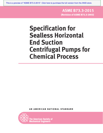
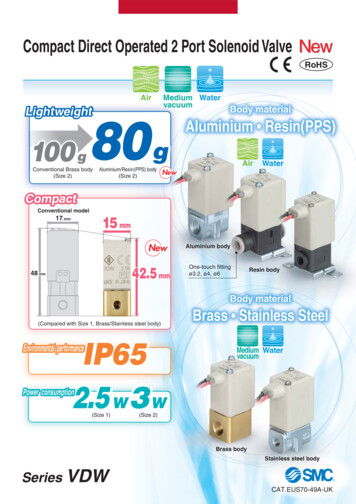
Technical leafletElectrically operated suction modulating control valves, type KVSDimensions and weightsKVS 42-54TypeConnectionInput output Input outputH1mmL1in./8 7/87KVS 4211/8 11/828 281 /8 1 /835 3515/8 15/842 421 /8 1 /842 4221/8 21/854 5435KVS .22 / .260.02.424.00.952.24.9 Danfoss A/S, (USCO/MR), 02-2007
Technical leafletElectrically operated suction modulating control valves, type KVS Danfoss A/S, (USCO/MR), 02-2007DKRCC.PD.VC1.A1.22 / RD4JE60211
Technical leafletElectrically operated suction modulating control valves, type KVS12DKRCC.PD.VC1.A1.22 / RD4JE602 Danfoss A/S, (USCO/MR
that provides best part load efficiency with zero-resistance maximum capacity The cage and orifice design is fully power balanced, so that bi-flow operation has equal performance and capacity in either direction. The port design includes a shut-off function with “solenoid tightness” in both flow directions.