Transcription
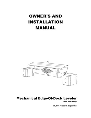
OWNER'S ANDINSTALLATIONMANUALMechanical Edge-Of-Dock LevelerFixed Rear Hinge20,25,&30,000 lb. Capacities
Mechanical EOD Leveler Owner's & Installation ManualTABLE OF CONTENTS1. Introduction . 32. Receipt Inspection. 33. Installation Diagram - Mechanical EOD Dock Leveler. 44. Installation Instructions. 54.1Final Inspection . 74.2Installation Types . 75. Routine Servicing And Maintenance.116. Component Identification . 117. Operator Daily Inspection. 128. Planned Maintenance . 129. Planned Maintenance Intervals. 139.1Maintenance Sequence. 1310. Safety Information . 1410.1 General. 1410.2 Safety Signs And Safety Messages . 1510.3 General Safety Rules . 1610.4 Safety Procedures. 1711. The Mechanical Edge of Dock Leveler - Functional Description . 1812. Operator Maintenance And Care . 1912.1 Daily Safety Inspection. 1912.2 Visual Checks. 1912.3 Operator's Daily Check List. 2112.4 Operating Hazards . 2213. Before Operating The Dock Leveler . 2513.1 Load Handling . 2513.2 Traveling With A Load . 2514. Operating Instructions – Typical . 2615. Operating Procedures - Pictorials . 2816. Trouble Shooting. 32Issue Date: 06/21/05 (Part # 411-253)Page 1
Mechanical EOD Leveler Owner's & Installation Manual17. Mechanical EOD Leveler - Parts Listings . 3417.1 General Assembly - 20,000 lb. Capacity - 66,72&78" Wide . 3417.2 General Assembly - 25,000 lb. Capacity - 66,72&78" Wide . 3617.3 General Assembly - 30,000 lb. Capacity - 66&72" Wide. 3817.4 General Assembly - 20,25,&30,000 lb. Capacity - 78&83" Wide . 4018. Service / Maintenance History . 4219. Warranty Policy . 43Page 2Issue Date: 06/21/05 (Part # 411-253)
Mechanical EOD Leveler Owner's & Installation Manual1. IntroductionRead and understand these instructions before commencing work.Responsibilities:The individuals assigned to perform the installation ofthe equipment are responsible for doing so incompliance with instructions contained herein.Date of Issue: 06/21/05, Part #411-253Assumptions:The individuals responsible for performing theseinstructions are capable and experienced with installingthis type of equipment.2. Receipt InspectionThis equipment has been thoroughly inspected prior toleaving the factory. The equipment should be thoroughlychecked for damage or loss occurring in transit, beforeaccepting delivery or installing.IMPORTANT! : IF ANY DAMAGE OR LOSS IS EVIDENT, A CLAIMMUST BE MADE AGAINST THE CARRIER.Issue Date: 06/21/05 (Part # 411-253)Page 3
Mechanical EOD Leveler Owner's & Installation Manual3. Installation Diagram - Mechanical EOD Dock LevelerCURBANGLEADJACENT TOHINGE SPOOLS1/4”BUMPER ANDEXTENSIONBRACKETVERTICAL WELD(BOTH ENDS)BACKFRAMELOCATE AND DRILL 5/8”HOLE INTO CONCRETEINSTALL (12) - 5/8” X 6”CONCRETE WEDGE ANCHORSPLUG WELDTO CURB ANGLE5/32” [4 mm]CURBANGLEBACKFRAMEFigure 1 : Mechanical Edge-of-Dock Leveler InstallationPage 4Issue Date: 06/21/05 (Part # 411-253)
Mechanical EOD Leveler Owner's & Installation Manual4. Installation InstructionsWARNING! : DO NOT WORK UNDER OR AROUND THE DOCKLEVELER BEING INSTALLED WITHOUT FIRST PLACING ADEQUATEBARRIERS TO POSITIVELY PREVENT VEHICLE TRAFFIC FROMENTERING THE WORK AREA.1. Inspect the loading dock curb angle andverify that it is firmly embedded andanchored in the concrete and isminimum 3" x 3" x 1/4" (75 x 75 x 6mm)steel. If there is no curb angle, ifanchoring or embedding isquestionable, or is not of minimum sizespecified, install a face plate followingthe instructions in Section 4.2 :Installation Types before proceedingwith the installation.WARNING! : THE EOD LEVELER MUST BE WELDED TO A FIRMLYEMBEDDED CURB ANGLE OR OTHER DOCK STEEL AS DESCRIBEDIN THE INSTALLATION INSTRUCTIONS. DO NOT ATTEMPT TO USEONLY BOLTS OR ANCHORS TO ATTACH THEDOCK LEVELER TO THE CONCRETE.2. Unband the Dock Leveler and discardall shipping material.WARNING! : USE CAUTION WHEN UNBANDING THE EOD LEVELER.KEEP HANDS CLEAR OF PINCH POINTS AND WEAR APPROPRIATESAFETY ATTIRE - GLASSES, GLOVES AND WORK BOOTS3. Using appropriate hoisting equipment,use the lifting eye located in the lip tosling the Dock Leveler into positionagainst the curb angle.WARNING! : USE CAUTION WHEN LIFTING OR MOVING THEEOD LEVELER. DO NOT ATTEMPT TO LIFT WITHOUT SUITABLEHOISTING EQUIPMENT CAPABLE OF LIFTING AS MUCH AS 600LBS.4. Position the back frame so that the topof the frame is 5/32" (4mm) below thelevel of the top of the curb angle (plus1/8" (4mm), minus 0" (4mm)). Ensuretop of frame is parallel with the top ofthe curb angle.5. Tack weld top of back frame securely tocurb angle.6. Assure back frame is firmly against curbangle or dock face concrete and plugweld the back frame to the curb angle atIssue Date: 06/21/05 (Part # 411-253)Page 5
Mechanical EOD Leveler Owner's & Installation Manualthe four circular holes in the frame. Ifcurb angle does not overlap theseholes, use the back plate as a templateand drill four holes 5/8" dia. x 6" (15mmx 150mm) deep, in the dock faceconcrete. Clean out holes and insertand permanently install appropriateconcrete wedge anchors. (See Figure1). Tighten enough to secure the BackFrame.7. Finish weld the top of the back frame tothe curb angle. Weld 1/4" x 5" (6mm x125mm) long welds on both ends of theback frame. Repeat the 1/4" weldsadjacent to and centered with the hingespools (approx. 5" long) across the fullwidth of the back frame.8. Vertical weld both ends of back frame tocurb angle, full length of vertical contact.Tighten Lag bolts at this time securely.9. Position the left-hand bumper bracket(as viewed when standing on thedriveway in front of the Dock Leveler) sothat there is 1/2" (13mm) clearancebetween the bracket side and thecontrol handle pocket, and the bracket islevel with the top of the curb angle.Weld all horizontal and vertical contactareas between bracket and curb angleand plug weld mounting holes thatoverlap curb angle. Install concretewedge anchors 5/8" x 6" (15mm x150mm) in mounting holes that are notwelded.10. Position the right-hand bumper bracketso that there is a 1/2" (13mm) clearancebetween the bracket and the dockleveler deck plate. Weld all horizontaland vertical contact areas betweenbracket and curb angle and plug weldmounting holes that overlap curb angle.Install concrete wedge anchors 5/8" x 6"(15mm x 150mm) in mounting holes thatare not welded.11. Install the control handle in the pocketon the left side of the deck. To do so,remove the bolt from the bottom of thehandle, insert handle through pocket,then re-install bolt through hole inhandle.12. Lubricate all pivot points using SAE30motor oil or equivalent.Page 6Issue Date: 06/21/05 (Part # 411-253)
Mechanical EOD Leveler Owner's & Installation Manual4.1 Final Inspection1. Clean up the entire work area and apply touchup paint to all welds, scratches and burns.2. Ensure all concrete wedge anchors have beensecurely tightened and / or locked.WARNING ! :READ AND UNDERSTAND THIS ENTIRE MANUALPRIOR TO OPERATING.3. Test operate the unit through several full cyclesof operation. Refer to Section 14 : OperatingProcedures. If problems are noted, See Section16 : Troubleshooting.4. Leave these Instructions with the Dock Levelerfor use by owner.4.2 Installation TypesCurb AngleCURBANGLEANCHORFigure 2 : Curb Angle Arrangement Must be poured-in with dock concrete. 3" x 3" x 1/4" minimum, steel curb angle. Weld-on concrete wedge anchors to be minimum 5/8"x 6" long located on 12" centers with one anchor 3"from each end.Issue Date: 06/21/05 (Part # 411-253)Page 7
Mechanical EOD Leveler Owner's & Installation ManualOptional Approach Ramp URBANGLEANCHORFigure 3 : Approach Ramp Arrangement Position ramp as illustrated. Outside edge of rampflush with outside edge of curb angle. Tack-weld ramp to curb angle. Drill 3/4" dia. holes using ramp as a template. Insert5/8" expansion sleeves (010-116). Install and tighten5/8" x 1-1/2" button-head bolts (010-117) using 3/8"Allen key wrench Weld the ramp to the curb angle as illustrated. 1/4" x5" welds on 9" centers.Note : All hardware must be purchasedseparately as part of an optional mounting kit.Consult your local distributor/dealer for moreinformation.Page 8Issue Date: 06/21/05 (Part # 411-253)
Mechanical EOD Leveler Owner's & Installation ManualFace Plate Types - For use on existing docks withno curb steelOne Piece Angle PlateBEVELEDEDGEFigure 4 : One Piece Angle Plate Arrangement 1/4" minimum plate thickness. Top plate 13" wide,face plate 10-" wide. Length to suit EOD Levelermodel. Place angle plate on existing dock as shown. Use asdrill template. Lag to sound concrete as follows:Top Plate - Drill 3/4" dia. x 3-1/2" deep holes. Insert 5/8"expansion sleeves (010-116). Install and tighten 5/8" x1-1/2" button-head bolts (010-117) using 3/8" Allen key.Face Plate - Drill 5/8" dia x 6" deep holes. Insert 5/8" x6" long concrete anchor wedges (010-108) and tighten.Note : All hardware must be purchasedseparately as part of an optional mounting kit.Consult your local distributor/dealer for moreinformation.Issue Date: 06/21/05 (Part # 411-253)Page 9
Mechanical EOD Leveler Owner's & Installation ManualTwo Piece Angle Plate(Welded together on Site)WELDBEVELEDEDGEFigure 5 : One Piece Angle Plate Arrangement 1/4" minimum plate thickness. Top plate 13" wide,face plate 10" wide. Length to suite EOD Levelermodel. Place top plate on top of existing dock, front edgeflush with dock face, full length. Drill 3/4" dia. x 3-1/2" deep holes using plate astemplate. Insert 5/8" expansion sleeves (010-116).Install and tighten 5/8" x 1-1/2" button-head bolts(010-117) using 3/8" Allen key wrench. Place face plate in position as shown. Position topedge for welding and tack-weld to top plate. Drill 5/8" dia. x 6" deep holes using plate as atemplate. Insert 5/8" x 6" long concrete wedgeanchors (010-108) and tighten. Weld the two plates together as illustrated. 1/4" x 5"long welds on 9" centers.Note : All hardware must be purchasedseparately as part of an optional mounting kit.Consult your local distributor/dealer for moreinformation.Page 10Issue Date: 06/21/05 (Part # 411-253)
Mechanical EOD Leveler Owner's & Installation Manual5. Routine Servicing And MaintenanceRegular maintenance and care of the Dock Leveler isvery important for cost and operation efficiency andmore importantly; operator safety. A faulty Dock Leveleris a potential source of danger to the operator, and toothe
Weld the two plates together as illustrated. 1/4" x 5" long welds on 9" centers. Note : All hardware must be purchased separately as part of an optional mounting File Size: 1MBPage Count: 51
