Transcription
Installing, Operating & MaintainingMUNCHKIN HIGH EFFICIENCY HEATERwith the “925” ControllerWARNINGIf the information in this manual is not followed exactly, a fire or explosion mayresult causing property damage, personal injury or loss of life.Do not store or use gasoline or other flammable vapors andliquids in the vicinity of this or any other appliance.WHAT TO DO IF YOU SMELL GAS Do not try to light any appliance. Do not touch any electrical switch: do not use any phone inyour building. Immediately call your gas supplier from a neighbor's phone.Follow the gas supplier's instructions. If you cannot reach your gas supplier, call the fire department.Installation and service must be performed by a qualifiedinstaller, service agency or the gas supplier.MH27745WARNINGThis manual must only be used by a qualified heating installer / servicetechnician. Failure to comply could result in severe personal injury, death orsubstantial property damage. It is also important to keep these Instructionswith the appliance.HEAT TRANSFER PRODUCTS, INC.120 BRALEY RD., E. FREETOWN, MA02717
USING THIS MANUALUSING THIS MANUALSPECIAL ATTENTION BOXESThroughout this manual you will see thesespecial attention boxes similar to this one,which are intended to supplement theinstructions and make special notice ofpotential hazards. These categories mean, inthe judgement of Heat Transfer Products, Inc.:NOTICEHeat Transfer Products manufactures bothASME and Non-ASME boilers. It is theresponsibility of the installer that the correctmodel has been selected for jurisdictionrequirements.DANGERDANGER indicates an imminently hazardoussituation which, if not avoided, will result indeath or serious injury.WARNINGWARNING indicates a potentially hazardoussituation which, if not avoided, could result indeath or serious injury.CAUTIONCAUTION Indicates a potentially hazardoussitutation which, if not avoided, may result inminor or moderate injury.CAUTIONCAUTION used without the safety alert symbolindicates a potentially hazardous situation which,if not avoided, may result in property damage.WARNINGS THIS UNIT IS FOR CATEGORY IV VENTING - 2 PIPE ONLY. THIS IS A SEALEDCOMBUSTION APPLIANCE. THIS HEATER INSTALLATION MUST CONFORM TO THE LATEST EDITION OF THE“NATIONAL FUEL GAS CODE” ANSI Z223.1 NFPA 54 AND OR CAN/CGA B149INSTALLATION CODES. STATE AND LOCAL CODES MIGHT ALSO APPLY TOINSTALLATION. WHERE REQUIRED BY THE AUTHORITY HAVING JURISDICTION, THEINSTALLATION MUST CONFORM TO THE STANDARDS FOR CONTROLS ANDSAFETY DEVICES FOR AUTOMATICALLY FIRED HEATERS, ANSI/ASME HEATERAND PRESSURE VESSEL CODE, Section IV, ALONG WITH CSD1. THE HEATER, GAS PIPING, WATER PIPING, VENTING AND ELECTRICAL MUST BEINSTALLED BY TRAINED & QUALIFIED PERSONNEL FAMILIAR WITHINSTALLATION PRACTICES, LOCAL CODE, LICENSING REQUIREMENTS. IF THE INFORMATION IN THESE INSTRUCTIONS ARE NOT FOLLOWED EXACTLY,A FIRE OR EXPLOSION MAY RESULT; CAUSING PROPERTY DAMAGE, PERSONALINJURY, OR DEATH. DO NOT STORE OR USE GASOLINE OR OTHER FLAMMABLE VAPORS ANDLIQUIDS IN THE VICINITY OF THIS OR ANY OTHER APPLIANCE; THE USE OF A LOW WATER CUT-OFF DEVICE MAY BE REQUIRED BY STATE ORLOCAL CODES IF THE MUNCHKIN IS INSTALLED ABOVE RADIATION LEVELS.2
TABLE OF CONTENTSTABLE OF CONTENTSPART 1 . . . . . . . . . . . . . . . . . . . . . .4 thru 8PART 5 . . . . . . . . . . . . . . . . . . . .22 thru 33GENERAL INFORMATIONPIPINGABCDHow It Operates . . . . . . . . . . . . . . . . . .4Munchkin Ratings and Dimensions . . .4Pre-installation Requirements . . . . . . .8Pressure Relief Valve . . . . . . . . . . . . . .9AHydronic piping withCirculators or Zone Valves . . . . . . . . .22Circulator Sizing . . . . . . . . . . . . . . . . .23Fill and Purge Heating System . . . . . .24Piping Illustrations . . . . . . . . . . . . . . .25BCDPART 2 . . . . . . . . . . . . . . . . . . . . .9 thru 11PART 6 . . . . . . . . . . . . . . . . . . . .34 thru 37ELECTRICALASTART UP PROCEDURESElectrical Connection . . . . . . . . . . . . . .9PART 3 . . . . . . . . . . . . . . . . . . . .12 thru 13GAS CONNECTIONABCGas Connection . . . . . . . . . . . . . . . . . .12Gas Piping . . . . . . . . . . . . . . . . . . . . . .12Gas Table . . . . . . . . . . . . . . . . . . . . . . .12PART 4 . . . . . . . . . . . . . . . . . . . .14 thru 21VENTINGABCDEFGGeneral . . . . . . . . . . . . . . . . . . . . . . . .14Approved Materials for Exhaust Ventand Intake Air Pipe . . . . . . . . . . . . . . .14Exhaust/Vent / Air IntakePipe Location . . . . . . . . . . . . . . . . . . . .14Exhaust Vent and Intake AirPipe Sizing . . . . . . . . . . . . . . . . . . . . . .16Exhaust Vent and Air IntakePipe Installation . . . . . . . . . . . . . . . . . .16Heater Removal from aCommon Vent System . . . . . . . . . . . .18Condensate Removal . . . . . . . . . . . . .18ABCDEFGHSequence of operation . . . . . . . . . . . .34Items to be checked beforelighting the Munchkin . . . . . . . . . . . . .34Lighting Instructions . . . . . . . . . . . . . .35Operating Instructions . . . . . . . . . . . .35Adjusting the Temperatureon the Munchkin Display . . . . . . . . . .36Status Menu . . . . . . . . . . . . . . . . . . . .36Test Mode . . . . . . . . . . . . . . . . . . . . . .37To Turn Off Gas to Appliance . . . . . . .37PART 7 . . . . . . . . . . . . . . . . . . . .38 thru 40TROUBLESHOOTINGABCMunchkin Error Code . . . . . . . . . . . . .38Boiler Error . . . . . . . . . . . . . . . . . . . . .38Boiler Fault . . . . . . . . . . . . . . . . . . . . .38PART 8 . . . . . . . . . . . . . . . . . . . .40 thru 44MAINTENANCEABCDEFMaintenance Procedures . . . . . . . . . .41Before Each Heating Season . . . . . . .41Condensate Cleaning Instructions . . .41Combustion ChamberCoil Cleaning Instructions . . . . . . . . . .42Munchkin Controller . . . . . . . . . . . . . .43Components Diagrams . . . . . . . . .44–453
GENERAL INFORMATIONPART 1. GENERAL INFORMATIONA. HOW IT OPERATESWhen the room thermostat calls for heat, the Munchkin control board will start the circulator and startto monitor the return temperature of the system before the heater will begin to heat the water. Oncethe controller has sensed a drop in the return water temperature below the temperature set pointminus the differential set point, the heater will start to heat the water. This eliminates the Munchkinstarting every time the thermostat calls for heat. This feature keeps the system from short cycling.Once the system has sensed the temperature difference, the Munchkin will activate the blower motorfor 5 seconds to pre-purge the system before starting the Munchkin. The Munchkin controller will nowstart to modulate the pre-mix burner based on analyzing the return temperature, supply watertemperature and the set point temperature. By compiling this information, the controller utilizes analgorithm to fully adjust the firing rate while maintaining the desired output temperature. The pre-mixburner fan has a direct drive current low-voltage motor with a pulse relay counting. This system allowsprecise control over the fan speed and combustion air volumes. Coupled with the Dungs gas valve andthe the swirl plate system which are set to provide a one-to-one ratio of precisely measured volumesof fuel to air, an accurate and instant burner output is achieved. This keeps the Munchkin running atthe highest efficiency.When the thermostat is satisfied, the Munchkin will then go through a 4 second post-purge cycle beforeshutting off. Every Munchkin heater is equipped with a display which will read the outlet temperature ofthe heater and then will illuminate a green light showing flame on. If a problem occurs, the front indicatorlight will turn red and the display will read a fault code; see Part 7, Section B/C.B. MUNCHKIN RATINGS AND DIMENSIONSPERFORMANCE RATINGSModelT50MT80M80M140M199MInput Modulation18,000 to 50,00019,000 to 80,00027,000 to 80,00046,000 to 140,00066,000 to 199,000DOE Heating16,000 to 46,00017,000 to 74,00025,000 to 74,00043,000 to 129,00061,000 to 183,000AFUE92%92%92%92%92 %Gas Connection Size3/4"3/4"3/4"3/4"3/4"Vent Dia.2"2"3"3"3"*Net waterCONNECTION ion1 1/4" NPT1 1/4" NPT1 1/4" NPT1 1/4" NPT1 1/4" NPTShipping Weight58 lbs.58 lbs.75 lbs.101 lbs.111 lbs.*IBR40,00064,00064,000112,000159,000
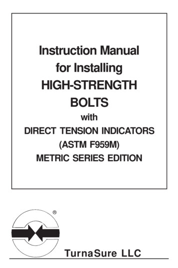
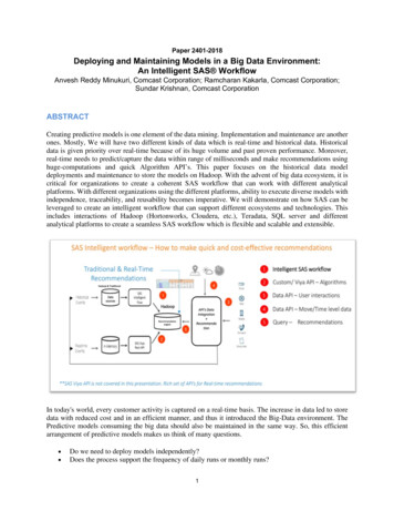
GENERAL INFORMATIONRECOMMENDED SERVICE CLEARANCES(NOTE: The Munchkin is rated atzero clearance to combustibles.)80M/140M/199MT50M/T80MFigure 1-1Figure 1-25
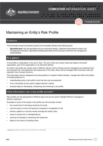
GENERAL INFORMATIONDIMENSIONST50M/T80MFigure 1-36
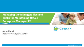
GENERAL INFORMATIONDIMENSIONS80MFigure 1-4140M/199MFigure 1-57
GENERAL INFORMATIONC. PRE-INSTALLATION REQUIREMENTGENERAL1. Munchkin Boilers are supplied completely assembled as packaged boilers. Thepackage should be inspected for damageupon receipt and any damage to the unitshould be reported to the shipping company and wholesaler. This boiler shouldbe stored in a clean, dry area.2. Carefully read these instructions and besure to understand the function of allconnections prior to beginning installation. Contact your Munchkin SalesRepresentative or the Heat TransferProducts, Inc. Customer ServiceDepartment for help in answering questions.3. This boiler must be installed by a qualified contractor. The boiler warranty maybe voided if the boiler is not installed correctly.4. This boiler needs to be installed on alevel floor. If the floor is not level, theboiler must be pitched back (1/4” pitchfor the 80M and 3/8” for the 140/199M.)This will assure proper flow to condensate drain in the bottom of the boiler.CODES & REGULATIONSInstallation and repairs are to be performed instrict accordance with the requirements of stateand local regulating agencies and codes dealingwith boiler and gas appliance installation.WARNINGLiquefied Petroleum (LP) Gas orPropane is heavier than air and, in theevent of a leak, may collect in lowareas such as basements or floordrains. The gas may then igniteresulting in a fire or explosion.ACCESSIBILITY CLEARANCES1. The Munchkin Boiler is certified for closet installations with zero clearance tocombustible construction. In addition, itis design certified for use on combustiblefloors.82. Refer to Figure 1.1 and Figure 1.2 for therecommended clearance to allow for reasonable access to the boiler. Local codesor special conditions may require greaterclearances.CAUTIONDo not install this boiler on carpeting.COMBUSTION AND VENTILATION AIR1. The Munchkin Boiler is designed only foroperation with combustion air pipedfrom outside (sealed combustion). PVCpipe must be supplied between the airinlet connection at the rear of the boilerthrough an outside wall.2. No additional combustion or ventilationair is required for this appliance.3. Refer to Section 4 of this manual,Venting, for specific instructions for piping combustion air.PLANNING THE LAYOUT1. Prepare sketches and notes showing thelayout of the boiler installation to minimize the possibility of interferences withnew or existing equipment, piping, venting and wiring.2. The following sections of this manualshould be reviewed for consideration oflimitations with respect to:a. Electrical Wiring: Part 2b. Gas Connection: Part 3c. Venting: Part 4f. Piping: Part 5Note: It is important to refer to thesite installation checklist in the backof this manual to assure proper andeffective installation.
GENERAL INFORMATION / ELECTRICALCAUTIONThe Munchkin is certified as an indoor appliance. Do not install the Munchkinoutdoors or locate where it will be exposed to freezing temperature. This includes allrelated piping and components. If the Munchkin is subjected to flood water orsubmersed in water, the Munchkin must be replaced.Note: Service clearance of the Munchkin: See Section 1, Figures 1-1 and 1-2.If the Munchkin is set up for liquefied petroleum (LP) gas, some geographic areas follow the UniformMechanical Code, section 304.6, “Liquefied petroleum gas burning appliances shall not be installed ina pit, basement or similar location where heavier-than-air gas might collect. Appliances so fueled, shallnot be installed in a below grade under-floor space or basement unless such location is provided withan approved means for removal of unburned gas.”CAUTIONCondensation removal: This is a condensing high efficiency appliance, thereforecondensation removal must be addressed to avoid damage to surrounding area orappliance. See Part (4) Section E for Condensate Requirements.WARNINGD. PRESSURE RELIEF VALVEA pressure relief valve is installed into the front right side manifold. We recommend a WATTS ¾"M 335 MI valve or equivalent and meets the requirements of ANSI/ASME Heater and PressureVessel Code, Section IV or CSA B51; Heater, Pressure Vessel and Piping Code as applicable forheating heaters. A ¾" pipe must be directed to a floor drain or suitable location within 6" of a drainor floor. Protect from freezing, do not plug or cap pressure relief valve. Serious explosion causingproperty damage and or loss of life could result. Under no circumstances should the relief valvebe eliminated, capped or plugged.PART 2. ELECTRICALA. ELECTRICAL CONNECTIONThe electrical connection for the Munchkin is on the left hand side of the unit. There is a ½” knockoutlocation for an electrical connection for both the incoming power and the central heating circulatorconnection. All electrical wiring must be performed by a qualified licensed electrician in accordancewith National Electrical Code ANSI Z223.1//NFPA 54 to and/or the Canadian Electrical Code, Part 1 CSAC22.1, or to the applicable codes and standards. For your convenience, we have labeled all the wiresthat need to be connected to operate the Munchkin.9
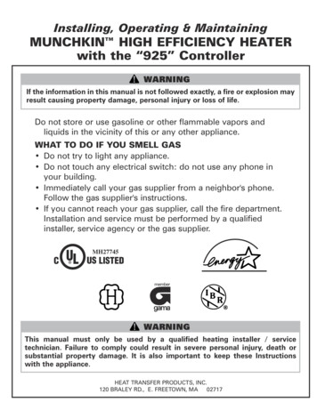
ELECTRICALCAUTIONElectrical wiring on the Incoming Power and Central Heating Circulator shall beconnected directly to the intended connection source and not be connected togetherinside the electric box provided. An Electrical Short will result and the Control boardwill have to be replaced! If Electrical Requirements of the Central Heating Circulatorexceeds 4 amps (or 3 amps on HA models only) please follow the wiring diagrams onFigures 2-1, 2-2 and 2-3 (this section).The electrical requirements are for standard 120 volts, 60 Hz 15 Amp service. This unit is wired with#18 awg and fused for no more than 15 Amps.DANGERIT IS EXTREMELY IMPORTANT THAT THIS UNIT BE PROPERLY GROUNDED!DANGERIT IS VERY IMPORTANT THAT THE BUILDING GROUND IS INSPECTED BY AQUALIFIED ELECTRICIAN PRIOR TO MAKING THIS CONNECTION!There are two ground points in the electrical compartment that must be connected to the buildingground system. Connect the building ground to the green ground screw and the green ground wireinside electrical box provided.The Incoming Power Supply is connected to the Black (Hot) and the White (Neutral).The MunchkinControl board is polarity sensitive. If the polarity is reversed, the Munchkin control will not sense aflame and lock out the system. The Orange and Brown wire are provided to the supply of 120 volts tothe Central Heating Circulator. Connect the Orange (Hot) and the Brown (Neutral) directly to the CentralHeating Circulator.DANGERThe Orange wire for the Central Heating Circulator is Switched Hot and must have awire nut if not connected to the Central Heating Circulator. Failure to follow thisinstruction will result in a short, and the Control Board will have to be replaced.Connect the gray wires to your heating thermostat (TT) connection. Your thermostat heat anticipatorsetting is .056 amp.CAUTIONDo not power zone valves directly from the heater transformer. Doing so will greatlyreduce the life of the transformer. Use a separate transformer sized to handle the totalelectric load of all zone valves.It is important that the electrical power is not turned on at this time. Double check all connections and thenturn the power on. The display that is provided with the Munchkin should now be reading the outlettemperature. Note: see Part 6/Startup Procedure section in the manual to change the temperature settingor run the heater.10
ELECTRICALDIAGRAM "A"DIAGRAM "B"WIRING DIAGRAM CONNECTING TO CIRCULATORWIRING DIAGRAM WITHOUT CONNECTION TO (GROUND)GRAYGRAYGREEN (GROUND)TNORMALLY OPENTHERMOSTATCONNECTIONBROWN (NEUTRAL)NORMALLY OPENTHERMOSTATCONNECTIONGREEN (GROUND)ORANGE (HOT)BLACKBROWN (NEUTRAL)WHITE (NEUTRAL)ORANGE (HOT)ORANGEBROWGR NEENGREEN (GROUND)IMPORTANT NOTE:BE CERTAIN THAT THE ORANGEWIRE IS SECURELY CAPED.FAILURE TO DO SO COULDRESULT IN INJURY OR FIREAND COULD DAMAGE THE DBUSELECTRICALSWITCH JUNCTION BOX120V 60 HZELECTRICALSWITCH JUNCTION BOX120V 60 HZFigure 2-1: Connection Wiring Directly toCentral Heating CirculatorZONETHERMOSTATR845ASWITCHINGRELAY ZONEBOILER"TT"GRAY1K15Figure 2-2: Connection Wiring without WiringCentral Heating CirculatorNote to Electrical Contractor: The orangewire is 120 Volt/4 Amp maximum for centralheating circulator only. Loads greater than 4amps or 3 amps for HA models only will blow thefuse on the board. The brown wire is the neutral wire for the central heating pump only.3TT1K11L1 HOT (BLACK)120 VOLT21K264BOILER"TT"GRAYZONECIRCULATORL2 NEUTRAL(WHITE)Figure 2-3: For circulator amp loads greaterthan 4 amps (3 amps for “HA” models) use thewiring diagram shown above. The brown andorange wires on the Munchkin boiler will not beused in this application and should beterminated so they do not cause a short circuit.11
GAS CONNECTIONPART 3. GAS CONNECTIONWARNINGFailure to follow all precautions could result in fire, explosion or death!A. GAS CONNECTIONThe gas supply shall have a maximum inlet pressure of lessthan 14" water column (350 mm), ½ pound pressure (3.5 kPa),and a minimum of 3.5" water column. The entire pipingsystem, gas meter and regulator must be sized properly toprevent pressure drop greater than 0.5" as stated in the NationalFuel Gas Code. This information is listed on the rating plate. It isvery important that you are connected to the type of gas as noted onthe rating plate. "LP" for liquefied petroleum, propane gas or, "Nat"natural or city gas. All gas connections must be approved by the local gas supplier, or utility in additionto the governing authority, prior to turning the gas supply on. The nipple provided is ½" and it ismandatory that a ¾" to ½" reducing coupling (provided) is used, threaded into the branch of a ¾" tee,and a drip leg fabricated, as per the National Fuel Gas code. You must ensure that the entire gas lineto the connection at the Munchkin is no smaller than ¾". Once all the inspections have beenperformed, the piping must be leak tested. If the leak test requirement is a higher test pressure thanthe maximum inlet pressure, you must isolate the Munchkin from the gas line. In order to do this, youmust shut the gas off using factory and field-installed gas cocks (following the lighting instructions inPart 6 Section B.) This will prevent high pressure. Failure to do so may damage the gas valve. In theevent the gas valve is exposed to a pressure greater than ½ PSI, 14" water column, the gas valve mustbe replaced. Never use an open flame (match, lighter, etc.) to check gas connections.B. GAS PIPING1.Run the gas supply line in accordance with all applicable codes.2.Locate and install manual shutoff valves in accordance with state and local requirements.C. GAS TABLERefer to Table (1) to size the supply piping to minimize pressure drop between meter or regulatorand unit.Maximum Capacity of Pipe in Cubic Feet of Gas per Hour for Gas Pressures of 0.5 psi or Less and aPressure Drop of 0.3 Inch water Column(TABLE 1)NominalIron Pipe InternalSizeDiameter(inches) (inches) 103/4.82427811.0495201 1/41.380 1,0501 1/21.610 1,60012(Based on a 0.60 Specific Gravity Gas)Length of Pipe 5011521544067060 70105 96195 180400 370610 320}BTU'SPERHOURX 1,000
This system allows precise control over the fan speed and combustion air volumes. Coupled with the Dungs gas valve and the the swirl plate system which are set to provide a one-to-one ratio of precisely measured volumes of fuel to air, an accurate and instant burner output is achieved. This keeps the Munchkin running at the highest efficiency.File Size: 2MBPage Count: 48