Transcription
“Best Practices for Proactively Monitoringand Maintaining Your Return Paths”Kelly WattsSenior Market Application EngineerCable Networks Division5808 Churchman BypassIndianapolis, IN 46203-6109kelly.watts@jdsu.comSee digital in a whole new light!
Global Leaders in the Markets We ServeAdvanced OpticalTechnologiesCurrency, Defense,Authentication, and Instrumentation2 2010 JDSU. All rights reserved.Communications &Commercial OpticalProductsCable, Telecom, Datacom, Submarine,Long Haul, Biotech, andMicroelectronicsJDSU CONFIDENTIAL & PROPRIETARY INFORMATIONCommunications Test &MeasurementService Provider, Government,Business, and Home Networks
87 Years of Experience in Test & MeasurementWandel &Goltermannfounded in1923, beginsto develop andmanufacturetest sets forcommunications1923TTCFoundedWavetekFoundedIn 19691974WavetekLaunchesPathTrakForms WWG1998TTC acquiresAppliedDigital Access,provider ofserviceassurancesystemsActernacreated bymerger ofWWG andTTC,combining theworld‘s 2ndand 3rd largestT&McompaniesWWG offersfirst Real-timeMPEGMonitoringSystem2002 DSAM islaunch19992000Circadiantacquired:InnocorJDSU adds industryacquired:leading ―stress test‖JDSU expandscapabilitiesportfolio for NEMsTest-Umacquired:ActernaacquiredJDSUenters homenetworkingtest market20052006Casabyteacquired:JDSU enterswireless serviceassurancearena2007 MVP-200Wins 4 DiamondAward from BGRTest ReviewWestover Scientific Finisar’s Network Agilent's NSDacquired:DivisionTools acquired:JDSU expandsacquired:JDSU adds StorageFiber Optics testCreates End-toNetwork Testportfolio with fiberEnd Wirelessinspection & cleaningTest Portfoliotools200820092010 AppliedDigitalAccess JDSFitel Uniphase3 2010 JDSU. All rights reserved.JDSU CONFIDENTIAL & PROPRIETARY INFORMATION
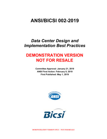
Bandwidth Demand is Growing Exponentially!All Video onDemand Unicastper SubscriberMegabits per Second10090High DefinitionVideo on Demand80Video Blogs70Podcasting60Video on Demand50Video Mail40Online Gaming30Digital Photos20VoIP10E-mailDigital MusicWeb BrowsingTime4 2010 JDSU. All rights reserved.JDSU CONFIDENTIAL & PROPRIETARY INFORMATION
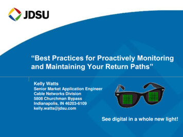
Market Trends More content to More devices 5 2010 JDSU. All rights reserved.IP devices growingAverage broadband speed willquadruple by 2014IP Traffic consumption willquadruple by 2014 (60% will bevideo traffic)JDSU CONFIDENTIAL & PROPRIETARY INFORMATION
The HFC Pipe to the Home is Huge!DOCSIS 3.0The BAD news is that ingress from one homecan potentially kill upstream services forhundreds of your subscribers!!!7 2010 JDSU. All rights reserved.JDSU CONFIDENTIAL & PROPRIETARY INFORMATION
DOCSIS 3.0 adds Capability to Bond up to4 Upstream 64QAM Carriers!Four times 6.4 MHz 25.6 MHz! (without guard-bands) 8Increased chances for laser clippingIncreased probability of problems caused by ingress,group delay, micro-reflections and other linear distortionsInability to avoid problem frequencies such as Citizens‘Band, Ham, Shortwave and CPD distortion beatsWhere are you going to place your sweep points? 2010 JDSU. All rights reserved.JDSU CONFIDENTIAL & PROPRIETARY INFORMATION
Today’s Agenda Getting ready for DOCSIS 3.0 - Optimize Your HFCnetwork now!– Verify optimal setup and performance (dynamic range) ofboth Optical & RF portion of the HFC network– Forward & Reverse sweep for unity gain throughout coaxialnetwork– Monitoring the Return Path Troubleshooting Upstream Impairments–––––9Trouble Shooting ToolsIngressCommon Path Distortion (CPD)Impulse NoiseLinear Distortions 2010 JDSU. All rights reserved.JDSU CONFIDENTIAL & PROPRIETARY INFORMATION
Major Operational Challenges Plant Certification and Maintenance:– Elevate plant performance to ensure reliable service– HFC: Sweep & advanced return path certification– Metro Optical: Fiber and transport analysis Monitor Performance:–––– Continuously monitor the health of your upstream and downstream carriersProactively identify developing problems before customers doMonitor both physical HFC & VoIP service call qualityUtilize advanced performance trending and analysis to prioritizeGet Installations Right the First Time– Improve installation practices to prevent service callbacks & churn– Verify physical, DOCSIS and PacketCable performance– Drive consistency across all technicians Troubleshoot Fast:– When issues occur, find and fix fast– Isolate and segment from NOC, dispatch right tech at right time– Field test tools that can find problems and verify fix10 2010 JDSU. All rights reserved.JDSU CONFIDENTIAL & PROPRIETARY INFORMATION
HFC Networks Combines fiber optics with coaxial distribution network Return path is more sensitive than the forward path Most of the ingress comes from home wiring on low valuetaps Wide variety of aging hardware with many connectorsToday‘s ―HFC‖ networks must be optimized for bothforward and reverse performance11 2010 JDSU. All rights reserved.JDSU CONFIDENTIAL & PROPRIETARY INFORMATION
Monitoring and Maintaining the Return Path Getting ready for DOCSIS 3.0 - Optimize Your HFCnetwork now!– Verify optimal setup and performance (dynamic range) ofboth Optical & RF portion of the HFC network– Forward & Reverse sweep for unity gain throughout coaxialnetwork– Monitoring the Return Path Troubleshooting Upstream Impairments– Trouble Shooting Tools– Ingress– Common Path Distortion (CPD)– Impulse Noise– Linear Distortions12 2010 JDSU. All rights reserved.JDSU CONFIDENTIAL & PROPRIETARY INFORMATION
Loose Fiber Connector SC connector not pushed in all the wayBeforeAfter13 2010 JDSU. All rights reserved.JDSU CONFIDENTIAL & PROPRIETARY INFORMATION
Types of Fiber ContaminationA fiber end face should be free of any contamination or defects, as shown below:SINGLEMODEFIBERCommon types of contamination and defects include the following:Dirt14 2010 JDSU. All rights reserved.OilPits & ChipsJDSU CONFIDENTIAL & PROPRIETARY INFORMATIONScratches
Where is it? – EverywhereYour biggest problem is right in front of you you just can’t see it!DIRT IS EVERYWHERE!15 Airborne, hands, clothing, bulkhead adapter,dust caps, test equipment, etc. The average dust particle is 2–5µ, whichis not visible to the human eye. A single spec of dust can be a majorproblem when embedded on or near thefiber core. Even a brand new connector can bedirty. Dust caps protect the fiber end face,but can also be a source of contamination. Fiber inspection microscopes give you aclear picture of the problems you are facing. 2010 JDSU. All rights reserved.JDSU CONFIDENTIAL & PROPRIETARY INFORMATION
Optimize the Optical Links in Your HFC Networks!Optical ReceiversFiber Nodes88888-Way SplittersCoaxVerify that all optical linkshave the correct light levelat the input of each opticalreceiver!16 2010 JDSU. All rights reserved.JDSU CONFIDENTIAL & PROPRIETARY INFORMATIONCable ModemsVerify that all fiberand RF connectionsare secure andproperly seated!
Too Much Optical Power into Optical ReceiverAbnormal risein the noisefloor abovediplex roll-offfrequency42 MHz diplex filterroll-off frequencyToo much optical power (light level) into the input of a returnoptical receiver can cause an abnormal rise in the noise floorabove the diplex filter roll-off frequencies.17 2010 JDSU. All rights reserved.JDSU CONFIDENTIAL & PROPRIETARY INFORMATION
Too Much Optical Power into Optical ReceiverAfter adding 2 dB ofoptical attenuationat the input of theoptical receiver, thenoise floor abovediplex roll-offfrequency nowlooks normal.42 MHz diplex filterroll-off frequency2 dB of additional optical attenuation was added to the returninput of the optical receiver and resulted in a “flatter noise floor”above the diplex filter roll-off frequencies.18 2010 JDSU. All rights reserved.JDSU CONFIDENTIAL & PROPRIETARY INFORMATION
Too Much Optical Power into Optical ReceiverAfter insertingsweep pulses intothe return path, thenoise floor abovediplex roll-offfrequency nowexhibits impulsenoise created bysweep pulses.Return Sweep Pulses42 MHz diplex filterroll-off frequencyWhen sweep pulses were injected into the return path,“impulse distortions” showed up in the noise floorabove the diplex filter roll-off frequencies.19 2010 JDSU. All rights reserved.JDSU CONFIDENTIAL & PROPRIETARY INFORMATION
Too Much Optical Power into Optical ReceiverNoise floor above diplex roll-offfrequency now looks normal.Return Sweep Pulses42 MHz diplex filterroll-off frequency6 dB of additional optical attenuation was added to the returninput of the optical receiver and resulted in a “flatter noise floor”above the diplex filter roll-off frequencies, even when sweep pulseswere injected into the retun path.20 2010 JDSU. All rights reserved.JDSU CONFIDENTIAL & PROPRIETARY INFORMATION
Setting the Transmitter “Window” RF input levels into a return laserdetermine the CNR of the return path.– Higher input – better CNR– Lower input – worse CNR Too much level and the laser ‗clips‘. Too little level and the noiseperformance is inadequate Must find a balance, or, ―set thewindow‖ the return laser must operatein– Not only with one carrier but all theenergy that in in the return path.– The return laser does not see only oneor two carriers it ‗sees‘ the all of theenergy (carriers) that in on the returnpath that is sent to it.*Source - Cisco Systems, Inc.21 2010 JDSU. All rights reserved.JDSU CONFIDENTIAL & PROPRIETARY INFORMATION
Measuring Upstream Carrier AmplitudesDynamic range of the return path in an HFC network is typicallysetup by injecting one or more CW test signals and thenmeasured with a typical spectrum analyzer or signal level meter.AmplitudeTest CW SignalCW1 Hz wide22 2010 JDSU. All rights reserved.1.6 MHz wideDOCSIS carrierJDSU CONFIDENTIAL & PROPRIETARY INFORMATION
Optical Link is Critical to Upstream Performance RF level is too high at input of return laser–––Verify light level at input of return optical receiverVerify RF level at input of return laserVerify RF spectrum above diplex frequency at input of return laser30 MHz36 MHz60 MHzWebView v2.5 FFT View of the Upstream23 2010 JDSU. All rights reserved.JDSU CONFIDENTIAL & PROPRIETARY INFORMATION72 MHz
Optimize the RF Output of the Optical ReceiverOptical ReceiversFiber NodesX dBmVX (Y?) dBmVX dBmVX (Y?) dBmVX dBmVX (Y?) dBmVX (Y?) dBmVX dBmVStore test results in a “birthcertificate” file folder for each node.All return path RF signal levels must be set toproper “X” (or Y?) output level at the opticalreceiver in the headend or hubsite with thecorrect “X” level injected at the node.24 2010 JDSU. All rights reserved.JDSU CONFIDENTIAL & PROPRIETARY INFORMATION
Measuring Upstream Carrier AmplitudesThese two DOCSIS carriers will have the same peak amplitudewhen hitting the input port of a CMTS at 0 dBmV “constant powerper carrier” and then measured with a typical spectrum analyzer.AmplitudeTest CW SignalCW1 Hz wide25 2010 JDSU. All rights reserved.3.2 MHz wide3.2 MHz wideJDSU CONFIDENTIAL & PROPRIETARY INFORMATION
Measuring Upstream Carrier AmplitudesThese three DOCSIS carriers will NOT have the same peakamplitude when hitting the input port of a CMTS at 0 dBmV“constant power per carrier” and then measured with a typicalspectrum analyzer or signal level meter.AmplitudeTest CW SignalCW1 Hz wide26 2010 JDSU. All rights reserved.1.6 MHz wide3.2 MHz wideJDSU CONFIDENTIAL & PROPRIETARY INFORMATION6.4 MHz wide
Optimize Dynamic Input Range of the CMTSCMTS26 dBadditional loss26 dBUpstreamOptical Receiver11 dBsplitter lossCoax8-WaySplitter0 dBmV injected CW 26 dBmV injected CW 37 dBmV injected CW-7 dBmV6.4 MHz wide carrier 19 dBmV6.4 MHz wide carrier 30 dBmV6.4 MHz wide carrierExample: Some systems will add 26 dB of external padding betweenthe splitter and CMTS to attenuate the injected CW signal down to apeak level of 0 dBmV at the input port of the CMTS. The CMTS istypically configured to instruct the 6.4 MHz modem carriers to hit theinput port of the CMTS at 0 dBmV ―constant power per carrier‖.27 2010 JDSU. All rights reserved.JDSU CONFIDENTIAL & PROPRIETARY INFORMATION
Monitoring and Maintaining the Return Path Getting ready for DOCSIS 3.0 - Optimize Your HFCnetwork now!– Verify optimal setup and performance (dynamic range) of bothOptical & RF portion of the HFC network– Forward & Reverse sweep for unity gain throughout coaxialnetwork– Monitoring the Return Path Troubleshooting Upstream Impairments– Trouble Shooting Tools– Ingress– Common Path Distortion (CPD)– Impulse Noise– Linear Distortions28 2010 JDSU. All rights reserved.JDSU CONFIDENTIAL & PROPRIETARY INFORMATION
WHY SWEEP? Less manpower needed Sweeping can reduce the number of service callsCracked hardlinefound with SWEEPChannel 12 videoproblemsInternet notworkingVOD notworking29 2010 JDSU. All rights reserved.JDSU CONFIDENTIAL & PROPRIETARY INFORMATION
WHY SWEEP? CATV amplifiers have a trade-off between noise and distortionperformance Tightly controlling frequency response provides the bestcompromise between noise and distortion.30 2010 JDSU. All rights reserved.JDSU CONFIDENTIAL & PROPRIETARY INFORMATION
Sweep Verifies Construction QualitySweep can find craftsmanship or componentproblems that aren’t revealed with other tests Damaged cable Poor connectorization Amplifier RF response throughout its frequency range Gain Slope Loose face plates, seizure screws, module hardware .All of these issues could lead to major ingress andmicro-reflection problems!31 2010 JDSU. All rights reserved.JDSU CONFIDENTIAL & PROPRIETARY INFORMATION
Balancing Amplifiers - Forward SweepBalancing amplifiers using tilt onlyHeadendLose Face Plate, or crack cableshieldNo TerminationFNode Reference Signal33 2010 JDSU. All rights reserved.Sweep responsewith a Resonant FrequencyAbsorption (A.K.A. suckout)JDSU CONFIDENTIAL & PROPRIETARY INFORMATIOND 492*Vp/FSweep responsewith standing waves
Sweeping the Return Path Choose operating levels that maximize thedistortion performance (dynamic range) ofyour return path Get all of the information that you can on yournodes and amps from your manufacturer Create a sweep procedure for your system– make up a chart showing injection levels at eachtest point38 2010 JDSU. All rights reserved.JDSU CONFIDENTIAL & PROPRIETARY INFORMATION
Optimize the RF Input to Return Sweep TransceiverOptical Receivers40 dBmVX dBmV8ReverseCombinerFiber NodesX dBmV840 dBmV40 dBmVX dBmV840 dBmVX dBmV80 dBmVPadSystem Sweep Transmitter 3SRStealth SweepFILE1abc 2def 3ghihelpFREQAUTO4jkl5mno 6pqrstatusCHANSETUP7stu 8vwx 9yz.space0 /-xCLEARalphaENTERlightFCNPad input of sweep receiver transceiver sothat 40 dBmV into node equals 0 dBmV atthe input of the return sweep ere are typically between 16 and 32 nodescombined together for return path sweeping40 2010 JDSU. All rights reserved.JDSU CONFIDENTIAL & PROPRIETARY INFORMATION
Stealth Sweep Pulses Compared to CarrierSweep TelemetryInjected at Node@ 40 dBmV?AmplitudeSweep PulsesInjected at Node@ 40 dBmV?FrequencyTest CW SignalInjected at Node@ 40 dBmV41 2010 JDSU. All rights reserved.JDSU CONFIDENTIAL & PROPRIETARY INFORMATION
Balancing Amplifiers - Reverse SweepInject correct “X” level into node testpoint and then take a sweep referenceTelemetry level shown below returnsweep trace should read around 0 dBmVif the SDA-5510 is padded properly42 2010 JDSU. All rights reserved.At next amp reverse sweep displaysthe effects of the network segmentbetween the last amp and this oneJDSU CONFIDENTIAL & PROPRIETARY INFORMATION
Optimize the HFC Pipe for Unity GainMaintain unity gain with constant inputsX dBmVX dBmVX dBmVX dBmVX dBmVX dBmVTelemetry 0 dBmVSet TP Loss as requiredUse the DSAM Field View Optionto inject a CW test signal into varioustest points and view remote spectrum43 2010 JDSU. All rights reserved.JDSU CONFIDENTIAL & PROPRIETARY INFORMATION
Sweep Pulses Compared to CarrierSweep TelemetryInjected at Node@ 40 dBmV?AmplitudeSweep PulsesInjected at Node@ 40 dBmV?Test CW SignalInjected at Node@ 40 dBmV46 2010 JDSU. All rights reserved.3.2 MHz wideJDSU CONFIDENTIAL & PROPRIETARY INFORMATION
Sweep Pulses Compared to CarriersAmplitudeSweep TelemetryInjected at Node@ 40 dBmV?6.4 MHzwideTest CW SignalInjected at Node@ 40 dBmV47Sweep PulsesInjected at Node@ 40 dBmV? 2010 JDSU. All rights reserved.500 kHz wideguard bandJDSU CONFIDENTIAL & PROPRIETARY INFORMATION
Sweep Pulses Compared to CarriersAmplitudeSweep TelemetryInjected at Node@ 40 dBmV?3.2 MHzwideTest CW SignalInjected at Node@ 40 dBmV48Stealth Sweep PulsesInjected at Node@ 40 dBmV? 2010 JDSU. All rights reserved.6.4 MHzwide500 kHzPeak level of 6.4 MHzcarriers at 34 dBmV6.4 MHzwide500 kHz6.4 MHzwide500 kHzJDSU CONFIDENTIAL & PROPRIETARY INFORMATION
Sweep Pulses Compared to CarriersAmplitudeSweep TelemetryInjected at Node@ 40 dBmV?Test CW SignalInjected at Node@ 40 dBmV49 2010 JDSU. All rights reserved.Sweep PulsesInjected at Node@ 40 dBmV?6.4 MHzwide6.4 MHzwide100 kHz wide6.4 MHzwide100 kHz wideJDSU CONFIDENTIAL & PROPRIETARY INFORMATION
Typical Sweep Interface with DOCSIS NetworkCMTSCMTS padding40 dBmVPadUpstream OpticalReceiver0 dBmVSystem Sweep TransmitterSETUPPRINT14LEVEL TILTC/NHUM7.abc2jkl 5stu8helpFREQghistatusmno6 pqr CHANalphavwx9 yzENTERxlightCLEARFCN8FiberPadSCAN SWEEPMODSPECTExternal attenuation shouldbe added after combining multiplenodes to achieve 0 dBmV level atsweep receiver input port50 2010 JDSU. All rights reserved.CoaxEstablish a 0 dBmV reference pointat the input of the sweep receiver!def3space0 /-Cable ModemsCombinerLossStealth SweepFILEAUTOCoaxialJumpersand 8-waysplitterFiber NodeJDSU CONFIDENTIAL & PROPRIETARY INFORMATION
Optimize the RF Input to SDA-5510 Sweep TransceiverOptical ReceiversX – 10 dBReverseCombiner830 dBmV30 dBmVX - 10 dB830 dBmVX - 10 dB80 dBmVPadSystem Sweep Transmitter 3SRStealth SweepFILE1abc 2def 3ghihelpFREQAUTO4jkl5mno 6pqrstatusCHANSETUP7stu 8vwx 9yzspace30 dBmVX - 10 dB8.Fiber Nodes0 /-xCLEARPad input of SDA-5510 so that 30 dBmVinto node equals 0 dBmV at the input ofthe SDA-5510 Return Sweep EPC/NHUMMODSPECTThere are typically between 16 and 32 nodescombined together for return path sweeping52 2010 JDSU. All rights reserved.JDSU CONFIDENTIAL & PROPRIETARY INFORMATION
Sweep Pulses Compared to CarrierAmplitudeSweep TelemetryInjected at Node@ 30 dBmV?Test CW SignalInjected at Node@ 40 dBmV53 2010 JDSU. All rights reserved.Sweep PulsesInjected at Node@ 30 dBmV?6.4 MHzwide6.4 MHzwide100 kHz wide6.4 MHzwide100 kHz wideJDSU CONFIDENTIAL & PROPRIETARY INFORMATION
Monitoring and Maintaining the Return Path Getting ready for DOCSIS 3.0 - Optimize Your HFCnetwork now!– Verify optimal setup and performance (dynamic range) of bothOptical & RF portion of the HFC network– Forward & Reverse sweep for unity gain throughout coaxialnetwork– Monitoring the Return Path Troubleshooting Upstream Impairments– Trouble Shooting Tools– Ingress– Common Path Distortion (CPD)– Impulse Noise– Linear Distortions54 2010 JDSU. All rights reserved.JDSU CONFIDENTIAL & PROPRIETARY INFORMATION
Typical PathTrak Interface with DOCSIS NetworkCMTSCMTS paddingPadUpstream OpticalReceiverCoaxial Jumpersand 8-way splitterFiber NodeCable Modems8FiberCoaxPathTrakRPM CardPadIt is critical to optimize thedynamic range of each RPM port!External attenuation may be added toachieve 0 dBmV peak level on widestupstream carrier at RPM input port66 2010 JDSU. All rights reserved.JDSU CONFIDENTIAL & PROPRIETARY INFORMATION
Optimize Dynamic Input Range of the RPM CardsPathTrakRPM Card19 dBadditional loss19 dBUpstreamOptical Receiver11 dBsplitter lossCoax8-WaySplitter7 dBmV injected CW 26 dBmV injected CW 37 dBmV injected CW0 dBmV6.4 MHz wide carrier 19 dBmV6.4 MHz wide carrier 30 dBmV6.4 MHz wide carrierExample: Some systems will add 19 dB of external p
JDSU enters home networking test market MVP-200 Wins 4 Diamond Award from BGR Test Review Finisar’s Network Tools acquired: JDSU adds Storage Network Test 87 Years of Experience in Test & Measurement 2010 Agilent's NSD Divisio