Transcription
Document No. :: IITK-GSDMA-EQ26-V3.0Final Report :: A - Earthquake CodesIITK-GSDMA Project on Building CodesDesign Example of a Six StoreyBuildingbyDr. H. J. ShahDepartment of Applied MechanicsM. S. University of BarodaVadodaraDr. Sudhir K JainDepartment of Civil EngineeringIndian Institute of Technology KanpurKanpur
This document has been developed under the project on Building Codessponsored by Gujarat State Disaster Management Authority, Gandhinagarat Indian Institute of Technology Kanpur. The views and opinions expressed are those of the authors and notnecessarily of the GSDMA, the World Bank, IIT Kanpur, or the Bureau ofIndian Standards. Comments and feedbacks may please be forwarded to:Prof. Sudhir K Jain, Dept. of Civil Engineering, IIT Kanpur, Kanpur208016, email: nicee@iitk.ac.in
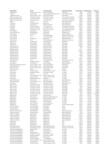
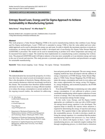
Design Example of a BuildingExample — Seismic Analysis and Design of a Six Storey BuildingProblem Statement:A six storey building for a commercial complex has plan dimensions as shown in Figure 1. The building islocated in seismic zone III on a site with medium soil. Design the building for seismic loads as per IS 1893(Part 1): 2002.General1. The example building consists of the mainblock and a service block connected byexpansion joint and is therefore structurallyseparated (Figure 1). Analysis and design formain block is to be performed.2 The building will be used for exhibitions, as anart gallery or show room, etc., so that there areno walls inside the building. Only externalwalls 230 mm thick with 12 mm plaster onboth sides are considered. For simplicity inanalysis, no balconies are used in the building.3. At ground floor, slabs are not provided and thefloor will directly rest on ground. Therefore,only ground beams passing through columnsare provided as tie beams. The floor beams arethus absent in the ground floor.4. Secondary floor beams are so arranged thatthey act as simply supported beams and thatmaximum number of main beams get flangedbeam effect.5. The main beams rest centrally on columns toavoid local eccentricity.6. For all structural elements, M25 grade concretewill be used. However, higher M30 gradeconcrete is used for central columns up toplinth, in ground floor and in the first floor.IITK-GSDMA-EQ26-V3.07. Sizes of all columns in upper floors are kept thesame; however, for columns up to plinth, sizesare increased.8. The floor diaphragms are assumed to be rigid.9. Centre-line dimensions are followed foranalysis and design. In practice, it is advisableto consider finite size joint width.10. Preliminary sizes of structural components areassumed by experience.11. For analysis purpose, the beams are assumedto be rectangular so as to distribute slightlylarger moment in columns. In practice a beamthat fulfils requirement of flanged section indesign, behaves in between a rectangular and aflanged section for moment distribution.12. In Figure 1(b), tie is shown connecting thefootings. This is optional in zones II and III;however, it is mandatory in zones IV and V.13. Seismic loads will be considered acting in thehorizontal direction (along either of the twoprincipal directions) and not along the verticaldirection, since it is not considered to besignificant.14. All dimensions are in mm, unless specifiedotherwise.Page 3
C1(0,0)3(7.5,0)(15,0)B1C2B2421Design Example of a BuildingC3C4 (22.5,0)B3AXAC10(22.5,7.5)C8BC11B 23F.B.B 20AB8B 19CC12(22.5,15)F.B.B11Service blockExpansionjointB9(15, 15)F.B.F.B.F.B.B10B6(15, 7.5)(7.5,15)B 16F.B.B 24B 21F.B.F.B.F.B.B 137.5 mB 17B7C9(0,15)CF.B.F.B.AC7(7.5, 7.5)F.B.B 147.5 mBB5F.B.xB 22C6C5(0,7.5)Main blockF.B.B4F.B.F.B.F.B.B 18B 157.5 (22.5,22.5)7.5 m1m300 6005 m 500 5004321Z7.5 m(a) Typical floor plan7.5 m 31.5 m 30.5 m Terrace 30.2 m75mM25 25.2 m65mM25 20.2 m5mM25 15.2 m5mM25 10.2 m35mM25 5.2 m24.1 mM25 1.1 m 25.5 m Fifth Floor5m 20.5 m Fourth Floor5m5y 15.5 m Third Floor5m4 10.5 m Second Floor5mx 5.5 m First Floor4m0.100.600.800.900.10300 6002.5 2.1 m Ground FloorPlinth 0.0600 600Tie(b) Part section A-A11.1 m 0.0 mStoreynumbersM25(c) Part frame sectionFigure 1 General lay-out of the Building.IITK-GSDMA-EQ26-V3.0Page 4
Design Example of a Building1.1.Data of the ExampleThe design data shall be as follows:: 4.0 kN/m2 at typical floorLive load: 1.5 kN/m2 on terraceFloor finish: 1.0 kN/m2Water proofing: 2.0 kN/m2Terrace finish: 1.0 kN/m2Location: Vadodara cityWind load: As per IS: 875-Not designed for windload, since earthquake loads exceed thewind loads.Earthquake load: As per IS-1893 (Part 1) - 2002Depth of foundation below ground: 2.5 mType of soil: Type II, Medium as per IS:1893Allowable bearing pressure: 200 kN/m2Average thickness of footing: 0.9 m, assume isolated footingsStorey height: Typical floor: 5 m, GF: 3.4 mFloors: G.F. 5 upper floors.Ground beams: To be provided at 100 mm below G.L.Plinth level: 0.6 mWalls: 230 mm thick brick masonry wallsonly at periphery.Material PropertiesConcreteAll components unless specified in design: M25 grade allEc 5 000f ck N/mm2 5 000f ck MN/m2 25 000 N/mm 2 25 000 MN/m 2 .For central columns up to plinth, ground floor and first floor: M30gradeEc 5 000f ck N/mm2 5 000f ck MN/m2 27 386 N/mm 2 27 386 MN/m 2 .SteelHYSD reinforcement of grade Fe 415 confirming to IS: 1786 is used throughout.1.2.Geometry of the BuildingThe general layout of the building is shown inFigure 1. At ground level, the floor beams FB areIITK-GSDMA-EQ26-V3.0not provided, since the floor directly rests onground (earth filling and 1:4:8 c.c. at plinth level)and no slab is provided. The ground beams arePage 5
Design Example of a Buildingprovided at 100 mm below ground level. Thenumbering of the members is explained as below.Foundation top – Ground floor1from upper to the lower part of the plan. Giving90o clockwise rotation to the plan similarly marksthe beams in the perpendicular direction. Tofloor-wise differentiate beams similar in plan (saybeam B5 connecting columns C6 and C7) invarious floors, beams are numbered as 1005,2005, 3005, and so on. The first digit indicates thestorey top of the beam grid and the last threedigits indicate the beam number as shown ingeneral layout of Figure 1. Thus, beam 4007 is thebeam located at the top of 4th storey whosenumber is B7 as per the general layout.Ground beams – First floor21.3.First Floor – Second floor3Second floor – Third floor41.3.1. Unit load calculationsAssumed sizes of beam and column sections are:Third floor – Fourth floor5Fourth floor – Fifth floor6Fifth floor - Terrace71.2.1.Storey numberStorey numbers are given to the portion of thebuilding between two successive grids of beams.For the example building, the storey numbers aredefined as follows:Portion of the building1.2.2.Storey no.Column numberIn the general plan of Figure 1, the columns fromC1 to C16 are numbered in a convenient way fromleft to right and from upper to the lower part ofthe plan. Column C5 is known as column C5 fromtop of the footing to the terrace level. However,to differentiate the column lengths in differentstories, the column lengths are known as 105,205, 305, 405, 505, 605 and 705 [Refer to Figure2(b)]. The first digit indicates the storey numberwhile the last two digits indicate column number.Thus, column length 605 means column length insixth storey for column numbered C5. Thecolumns may also be specified by using grid lines.1.2.3.Floor beams (Secondary beams)All floor beams that are capable of free rotation atsupports are designated as FB in Figure 1. Thereactions of the floor beams are calculatedmanually, which act as point loads on the mainbeams. Thus, the floor beams are not consideredas the part of the space frame modelling.1.2.4.Main beams numberBeams, which are passing through columns, aretermed as main beams and these together with thecolumns form the space frame. The general layoutof Figure 1 numbers the main beams as beam B1to B12 in a convenient way from left to right andIITK-GSDMA-EQ26-V3.0Gravity Load calculationsColumns: 500 x 500 at all typical floorsArea, A 0.25 m2, I 0.005208 m4Columns: 600 x 600 below ground levelArea, A 0.36 m2, I 0.0108 m4Main beams: 300 x 600 at all floorsArea, A 0.18 m2, I 0.0054 m4Ground beams: 300 x 600Area, A 0.18 m2, I 0.0054 m4Secondary beams: 200 x 600Member self- weights:Columns (500 x 500)0.50 x 0.50 x 25 6.3 kN/mColumns (600 x 600)0.60 x 0.60 x 25 9.0 kN/mGround beam (300 x 600)0.30 x 0.60 x 25 4.5 kN/mSecondary beams rib (200 x 500)0.20 x 0.50 x 25 2.5 kN/mMain beams (300 x 600)0.30 x 0.60 x 25 4.5 kN/mSlab (100 mm thick)0.1 x 25 2.5 kN/m2Brick wall (230 mm thick)0.23 x 19 (wall) 2 x 0.012 x 20 (plaster) 4.9 kN/m2Page 6
Design Example of a BuildingFloor wall (height 4.4 m)4.4 x 4.9 21.6 kN/mMain beams B1–B2–B3 and B10–B11–B12ComponentGround floor wall (height 3.5 m)3.5 x 4.9 17.2 kN/m0.5 x 2.5 (5.5 1.5)Terrace parapet (height 1.0 m)1.0 x 4.9 4.9 kN/mParapet6.9 1.90 04.9 04.9 0Total11.8 1.94.9 0kN/mkN/mSlab load calculationsComponentTerraceTypical(DL LL)(DL LL)Self (100 mmthick)2.5 0.02.5 0.0Waterproofing2.0 0.00.0 0.0Floor finish1.0 0.01.0 0.0Live load0.0 1.50.0 4.0Total5.5 1.5kN/m23.5 4.0kN/m21.3.3.B2From SlabGround floor wall (height 0.7 m)0.7 x 4.9 3.5 kN/m1.3.2.B1-B3Beam and frame load calculations:Two point loads on one-third span points forbeams B2 and B11 of (61.1 14.3) kN from thesecondary beams.Main beams B4–B5–B6, B7–B8–B9, B16–B17– B18 and B19–B20–B21From slab0.5 x 2.5 x (5.5 1.5) 6.9 1.9 kN/mTotal 6.9 1.9 kN/mTwo point loads on one-third span points for allthe main beams (61.1 14.3) kN from thesecondary beams.Main beams B13–B14–B15 and B22–B23–B24ComponentB13 – B15B14B22 – B24B23----6.9 1.9Parapet4.9 04.9 0Total4.9 011.8 1.9kN/mFrom Slab0.5 x 2.5 (5.5 1.5)(1) Terrace level:Floor beams:From slabkN/m2.5 x (5.5 1.5) 13.8 3.8 kN/mSelf weight 2.5 0 kN/mTotal 16.3 3.8 kN/mTwo point loads on one-third span points forbeams B13, B15, B22 and B24 of (61.1 14.3)kN from the secondary beams. 61.1 14.3 kN.(2) Floor Level:Reaction on main beam0.5 x 7.5 x (16.3 3.8)Floor Beams:Note: Self-weights of main beams and columnswill not be considered, as the analysis softwarewill directly add them. However, in calculationof design earthquake loads (section 1.5), thesewill be considered in the seismic weight.IITK-GSDMA-EQ26-V3.0From slab2.5 x (3.5 4.0)Self weightTotalReaction on main beam0.5 x 7.5 x (11.25 10.0) 8.75 10 kN/m2.5 0 kN/m11.25 10 kN/m 42.2 37.5 kN.Page 7
Design Example of a BuildingMain beams B1–B2–B3 and B10–B11–B12ComponentB1 – B3B2Two point loads on one-third span points forbeams B13, B15, B22 and B24 ofFrom Slab0.5 x 2.5 (3.5 4.0)4.4 5.00 0Wall21.6 021.6 0Total26.0 5.0 21.6 0kN/mkN/m(42.2 7.5) kN from the secondary beams.(3) Ground level:Two point loads on one-third span points forbeams B2 and B11 (42.2 37.5) kN from thesecondary beams.Outer beams: B1-B2-B3; B10-B11-B12; B13B14-B15 and B22-B23-B24Walls: 3.5 m high17.2 0 kN/mInner beams: B4-B5-B6; B7-B8-B9; B16B17-B18 and B19-B20-B21Main beams B4–B5–B6, B7–B8–B9, B16–B17–B18 and B19–B20–B21Walls: 0.7 m highFrom slab 0.5 x 2.5 (3.5 4.0) 4.4 5.0 kN/mThe loading frames using the above-calculatedbeam loads are shown in the figures 2 (a), (b), (c)and (d). There are total eight frames in thebuilding. However, because of symmetry, framesA-A, B-B, 1-1 and 2-2 only are shown.Total 4.4 5.0 kN/mTwo point loads on one-third span points for allthe main beams (42.2 37.5) kN from thesecondary beams.Main beams B13–B14–B15 andB22–B23–B24ComponentB13 – B15B14B22 – B24B23----4.4 5.0From Slab0.5 x 2.5 (3.5 4.0)Wall21.6 021.6 0Total21.6 kN/m0 26.0 5.0kN/mIITK-GSDMA-EQ26-V3.03.5 0 kN/mLoading framesIt may also be noted that since LL (3/4) DL inall beams, the loading pattern as specified byClause 22.4.1 (a) of IS 456:2000 is not necessary.Therefore design dead load plus design live loadis considered on all spans as per recommendationsof Clause 22.4.1 (b). In design of columns, it willbe noted that DL LL combination seldomgoverns in earthquake resistant design exceptwhere live load is very high. IS: 875 allowsreduction in live load for design of columns andfootings. This reduction has not been consideredin this example.Page 8
Design Example of a Building61.1 14.361.1 14.3 kN(11.8 1.9) kN/m(11.8 1.9) kN/m(4.9 0) kN/m7002(26 5) kN/m(26 5) kN/m(21.6 0) kN/m6002(26 5) kN/m(26 5) kN/m(21.6 0) kN/m5002(26 5) kN/m(26 5) kN/m(21.6 0) kN/m4002(26 5) kN/m(26 5) kN/m(21.6 0) kN/m3002(26 5) kN/m(26 5) kN/mC2B27.5 m(17.2 0) kN/m103102(17.2 0) kN/m100220420031003C3B3104(21.6 0) kN/m2002203202201(17.2 0) kN/m1014.1 m20011.1 m30442.2 37.5 42.2 37.5 kN30033033023015m30017.5 m40442.2 37.5 42.2 37.5 kN40034034024015m4001B150442.2 37.5 42.2 37.5 kN50035035025015m5001C160442.2 37.5 42.2 37.5 kN60036036026015m6001100170442.2 37.5 42.2 37.5 kN70037037027015m7001C47.5 mFigure 2 (a) Gravity Loads: Frame AAIITK-GSDMA-EQ26-V3.0Page 9
Design Example of a Building(4.4 5) kN/m2004C51004B47.5 m42.2 37.5 42.2 37.5 kN(4.4 5) kN/m300542.2 37.5 42.2 37.5 kN(4.4 5) kN/m2005C61005B5(4.4 5) kN/m500642.2 37.5 42.2 37.5 kN(4.4 5) kN/m400642.2 37.5 42.2 37.5 kN(4.4 5) kN/m300642.2 37.5 42.2 37.5 kN(4.4 5) kN/m200670860842.2 37.5 42.2 37.5 kN508707607(4.4 5) kN/m6006408(4.4 5) kN/m400542.2 37.5 42.2 37.5 kN30842.2 37.5 42.2 37.5 kN(3.5 0) kN/m106(3.5 0) kN/m(4.4 5) kN/m500550770660620620542.2 37.5 42.2 37.5 kN42.2 37.5 42.2 37.5 kN(6.9 1.9) kN/m7006208(4.4 5) kN/m3004(4.4 5) kN/m600561.1 14.3 kN(3.5 0) kN/mC77.5 m1006B610830542.2 37.5 42.2 37.5 kN42.2 37.5 42.2 37.5 kN407(4.4 5) kN/m4004(6.9 1.9) kN/m700561.1 14.330740542.2 37.5 42.2 37.5 kN61.1 14.3 kN207(4.4 5) kN/m500461.1 14.310750542.2 37.5 42.2 37.5 kN506605(4.4 5) kN/m6004406(6.9 1.9) kN/m700430670561.1 14.3 kN42.2 37.5 42.2 37.5 kN1051.1 m4.1 m5m5m5m5m5m61.1 14.3C87.5 mFigure 2(b) Gravity Loads: Frame BBIITK-GSDMA-EQ26-V3.0Page 10
Design Example of a Building61.1 14.3 61.1 14.3 kN61.1 14.3 61.1 14.3 kN42.2 37.5 kN(21.6 0) kN/m2013C 13B 137.5 mC91014B 14701705(26 5) kN/m201442.2 37.5 kN60150140142.2 37.5(21.6 0) kN/m301542.2 37.542.2 37.5 kN(21.6 0) kN/m2015(17.2 0) kN/m1091131.1 m(17.2 0) kN/m101360530942.2 37.542.2 37.5 kN(21.6 0) kN/m4015(26 5) kN/m30142093132134.1 m5m(21.6 0) kN/m301342.2 37.530142.2 37.5 kN42.2 37.5 kN20142.2 37.5(26 5) kN/m40144094135m(21.6 0) kN/m401342.2 37.5(17.2 0) kN/mC57.5 m1015B 1510142.2 37.5 kN42.2 37.5 kN(21.6 0) kN/m501550542.2 37.5(26 5) kN/m50145095135m(21.6 0) kN/m501340542.2 37.5 kN42.2 37.5(21.6 0) kN/m601530542.2 37.5(26 5) kN/m60146096135m(21.6 0) kN/m601320542.2 37.5 kN(4.9 0) kN/m701510542.2 37.5(11.8 1.9) kN/m70147097135m(4.9 0) kN/m7013C17.5 mFigure 2(c) Gravity Loads: Frame 1-1IITK-GSDMA-EQ26-V3.0Page 11
Design Example of a Building(4.4 5) kN/m40177.5 mC 101017B 17(4.4 5) kN/m2018702602502402302(3.5 0) kN/m106110(3.5 0) kN/m42.2 37.5 42.2 37.5 kN202(4.4 5) kN/m201730642.2 37.5 42.2 37.5 kN42.2 37.5 42.2 37.5 kN(4.4 5) kN/m301820631042.2 37.5 42.2 37.5 kN210314214(4.4 5) kN/m3017(3.5 0) kN/m1141.1 m4.1 m5m(4.4 5) kN/m301642.2 37.5 42.2 37.5 kN42.2 37.5 42.2 37.5 kN(4.4 5) kN/m401840642.2 37.5 42.2 37.5 kN4104145m(4.4 5) kN/m401642.2 37.5 42.2 37.5 kN42.2 37.5 42.2 37.5 kN(4.4 5) kN/m50185065105145m(4.4 5) kN/m501742.2 37.5 42.2 37.5 kNB 1642.2 37.5 42.2 37.5 kN42.2 37.5 42.2 37.5 kN(4.4 5) kN/m601860642.2 37.5 42.2 37.5 kN(4.4 5) kN/m5016C 1442.2 37.5 42.2 37.5 kN61.1 14.3 kN(6.9 1.9) kN/m7018(4.4 5) kN/m60176106145m(4.4 5) kN/m6016101661.1 14.370642.2 37.5 42.2 37.5 kN(4.4 5) kN/m201661.1 14.3 kN(6.9 1.9) kN/m70177107145m(6.9 1.9) kN/m701661.1 14.3C67.5 m1018B 1810261.1 14.3 61.1 14.3 kNC27.5 mFigure 2(d) Gravity Loads: Frame 2-2IITK-GSDMA-EQ26-V3.0Page 12
Design Example of a Building1.4.Seismic Weight CalculationsThe seismic weights are calculated in a mannersimilar to gravity loads. The weight of columnsand walls in any storey shall be equallydistributed to the floors above and below thestorey. Following reduced live loads are used foranalysis: Zero on terrace, and 50% on other floors[IS: 1893 (Part 1): 2002, Clause 7.4)(1) Storey 7 (Terrace):From slabParapet22.5 x 22.5 (5.5 0)4 x 22.5 (4.9 0)Walls0.5 x 4 x 22.5 x(21.6 0)Secondary 18 x 7.5 x (2.5 0)beamsMain8 x 22.5 x (4.5 0)beamsColumns0.5 x 5 x 16 x(6.3 0)TotalDL LL2 784 0441 0972 0WallsSecondarybeamsMainbeamsColumns22.5 x 22.5 x(3.5 0.5 x 4)4 x 22.5 x(21.6 0)18 x 7.5 x(2.5 0)8 x 22.5 x(4.5 0)16 x 5 x(6.3 0)Total810 0252 0DL LL1 772 1 0131 944 0338 0810 0504 05 368 1 013 6 381 kNWallsWallsSecondarybeamsMainbeams22.5 x 22.5 x(3.5 0.5 x 4)0.5 x 4 x 22.5 x(21.6 0)0.5 x 4 x 22.5 x(17.2 0)18 x 7.5 x(2.5 0)8 x 22.5 x(4.5 0)IITK-GSDMA-EQ26-V3.0TotalDL LL1 772 1 013972 0774 0459 05 125 1 013 6 138 kN(4) Storey 1 (plinth):WallsDL LL774 00.5 x 4 x 22.5(17.2 0)0.5 x 4 x 22.5 x(3.5 0)WallsMainbeamsColumn158 08 x 22.5 x(4.5 0)16 x 0.5 x 4.1 x(6.3 0)16 x 0.5 x 1.1 x(9.0 0)Total810 0206 079 02 027 0 2 027 kNSeismic weight of the entire building5 597 0 5 597 kN(3) Storey 2:From slab16 x 0.5 x (5 4.1) x (6.3 0)338 0(2) Storey 6, 5, 4, 3:From slabColumns 5 597 4 x 6 381 6 138 2 027 39 286 kNThe seismic weight of the floor is the lumpedweight, which acts at the respective floorlevel at the centre of mass of the floor.1.5.Design Seismic LoadThe infill walls in upper floors may contain largeopenings, although the solid walls are consideredin load calculations. Therefore, fundamental timeperiod T is obtained by using the followingformula:Ta 0.075 h0.75[IS 1893 (Part 1):2002, Clause 7.6.1] 0.075 x (30.5)0.75 0.97 sec.Zone factor, Z 0.16 for Zone IIIIS: 1893 (Part 1):2002, Table 2Importance factor, I 1.5 (public building)Medium soil site and 5% damping338 0810 0S a 1.36 1.402g 0.97IS: 1893 (Part 1): 2002, Figure 2.Page 13
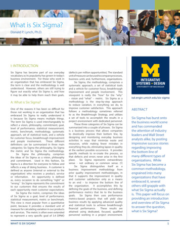
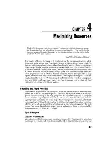
Design Example of a BuildingTable1. Distribution of Total Horizontal1.5.1.Load to Different Floor LevelsStorey Wi(kN)7654321Totalhi(m)5 5976 3816 3816 3816 3816 1382 02730.225.220.215.210.25.21.1Wihi2x10-35 1054 0522 6041 474664166314 068Qi Wi h i2Vi(kN) Wi h i2x VB(kN)480380244138621601 3204808601 1041 2421 3041 3201 320Ductile detailing is assumed for the structure.Hence, Response Reduction Factor, R, is takenequal to 5.0.It may be noted however, that ductile detailing ismandatory in Zones III, IV and V.Hence, Z2 Design eccentricity is given byedi 1.5 esi 0.05 bi oresi – 0.05 biIS 1893 (Part 1): 2002, Clause 7.9.2.S a 1.36 1.402g 0.97IS: 1893 (Part 1): 2002, Figure 2.Ah Accidental eccentricity:S aRgIFor the present case, since the building issymmetric, static eccentricity, esi 0.0.05 bi 0.05 x 22.5 1.125 m.Thus the load is eccentric by 1.125 m from masscentre. For the purpose of our calculations,eccentricity from centre of stiffness shall becalculated. Since the centre of mass and the centreof stiffness coincide in the present case, theeccentricity from the centre of stiffness is also1.125 m.Accidental eccentricity can be on either side (thatis, plus or minus). Hence, one must considerlateral force Qi acting at the centre of stiffnessaccompanied by a clockwise or an anticlockwisetorsion moment (i.e., 1.125 Qi kNm or -1.125 QikNm).Forces Qi acting at the centres of stiffness andrespective torsion moments at various levels forthe example building are shown in Figure 3.Note that the building structure is identical alongthe X- and Z- directions, and hence, thefundamental time period and the earthquakeforces are the same in the two directions.0.16 1.5 1.402 0.033625Base shear, VB Ah W 0.0336 x 39 286 1 320 kN.The total horizontal load of 1 320 kN is nowdistributed along the height of the building as perclause 7.7.1 of IS1893 (Part 1): 2002. Thisdistribution is shown in Table 1.IITK-GSDMA-EQ26-V3.0Page 14
Design Example of a BuildingMass centre( Centre of stiffness)540 kNm480 kN5m380 kN428 kNm5m244 kN275 kNm138 kN155 kNm62 kN70 kNm5m5m5m18 kNm16 kN1.1 m22.50 kNm0 kNm4.1 m22.5 mAll columns not shown for clarityFigure not to the scaleFigure 3IITK-GSDMA-EQ26-V3.0Accidental Eccentricity Inducing Torsion in the BuildingPage 15
Design Example of a Building1.6.Analysis by Space FramesThe space frame is modelled using standardsoftware. The gravity loads are taken from Figure2, while the earthquake loads are taken fromFigure 3. The basic load cases are shown in Table2, where X and Z are lateral orthogonal directions.Table 2 Basic Load Cases Used for AnalysisNo.Load caseDirections1DLDownwards2IL(Imposed/Live load)Downwards3EXTP ( Torsion) X;Clockwisetorsion due to EQ4EXTN (-Torsion) X; Anti-Clockwisetorsion due to EQ5EZTP ( Torsion) Z; Clockwisetorsion due to EQ6EZTN (-Torsion) Z; Anti-Clockwisetorsion due to EQFor design of various building elements (beams orcolumns), the design data may be collected fromcomputer output. Important design forces forselected beams will be tabulated and showndiagrammatically where needed. . In loadcombinations involving Imposed Loads (IL), IS1893 (Part 1): 2002 recommends 50% of theimposed load to be considered for seismic weightcalculations. However, the authors are of theopinion that the relaxation in the imposed load isunconservative. This example therefore, considers100% imposed loads in load combinations.For above load combinations, analysis isperformed and results ofdeflections in eachstorey and forces in various elements areobtained.Table 3 Load Combinations Used for DesignNo.Load combination11.5 (DL IL)21.2 (DL IL EXTP)31.2 (DL IL EXTN)41.2 (DL IL – EXTP)51.2 (DL IL – EXTN)EZTN: EQ load in Z direction with torsion negative.61.2 (DL IL EZTP)1.7.71.2 (DL IL EZTN)81.2 (DL IL – EZTP)91.2 (DL IL – EZTN)101.5 (DL EXTP)1.5 (DL EL)111.5 (DL EXTN)0.9 DL 1.5 EL121.5 (DL – EXTP)131.5 (DL – EXTN)141.5 (DL EZTP)151.5 (DL EZTN)161.5 (DL – EZTP)171.5 (DL – EZTN)EXTP: EQ load in X direction with torsion positiveEXTN: EQ load in X direction with torsion negativeEZTP: EQ load in Z direction with torsion positiveLoad CombinationsAs per IS 1893 (Part 1): 2002 Clause no. 6.3.1.2,the following load cases have to be considered foranalysis:1.5 (DL IL)1.2 (DL IL EL)Earthquake load must be considered for X, -X, Z and –Z directions. Moreover, accidentaleccentricity can be such that it causes clockwiseor anticlockwise moments. Thus, EL aboveimplies 8 cases, and in all, 25 cases as per Table 3must be considered. It is possible to reduce theload combinations to 13 instead of 25 by notusing negative torsion considering the symmetryof the building. Since large amount of data isdifficult to handle manually, all 25-loadcombinations are analysed using software.IITK-GSDMA-EQ26-V3.0Page 16
Design Example of a Building180.9 DL 1.5 EXTP190.9 DL 1.5 EXTN200.9 DL - 1.5 EXTP210.9 DL - 1.5 EXTN220.9 DL 1.5 EZTP230.9 DL 1.5 EZTN240.9 DL - 1.5 EZTP250.9 DL - 1.5 EZTN1.8.Maximum drift is for fourth storey 17.58 mm.Maximum drift permitted 0.004 x 5000 20mm. Hence, ok.Sometimes it may so happen that the requirementof storey drift is not satisfied. However, as perClause 7.11.1, IS: 1893 (Part 1): 2002; “For thepurpose of displacement requirements only, it ispermissible to use seismic force obtained from thecomputed fundamental period (T ) of the buildingwithout the lower bound limit on design seismicforce.” In such cases one may check storey driftsby using the relatively lower magnitude seismicforces obtained from a dynamic analysis.1.9.Storey DriftAs per Clause no. 7.11.1 of IS 1893 (Part 1):2002, the storey drift in any storey due tospecified design lateral force with partial loadfactor of 1.0, shall not exceed 0.004 times thestorey height. From the frame analysis thedisplacements of the mass centres of variousfloors are obtained and are shown in Table 4along with storey drift.Since the building configuration is same inboth the directions, the displacement valuesare same in either direction.Displacement(mm)It is necessary to check the stabilityindices as per Annex E of IS 456:2000 for allstoreys to classify the columns in a given storeyas non-sway or sway columns. Using data fromTable 1 and Table 4, the stability indices areevaluated as shown in Table 5. The stability indexQsi of a storey is given byQsi Storeydrift(mm)7 (Fifth floor)79.437.236 (Fourth floor)72.2012.195 (Third floor)60.0115.68uuH u hsWhere Pu4 (Second floor)44.3317.583 (First floor)26.7517.262 (Ground floor)9.499.081 (Below plinth)0.410.410 (Footing top)00 sum of axial loads on all columns inthe ith storeyUu elastically computed first orderlateral deflectionHu total lateral force acting within thestoreyhsIITK-GSDMA-EQ26-V3.0 P ΔQsi stability index of ith storeyTable 4 Storey Drift CalculationsStoreyStability Indices height of the storey.As per IS 456:2000, the column is classified asnon-sway if Qsi 0.04, otherwise, it is a swaycolumn. It may be noted that both sway and nonsway columns are unbraced columns. For bracedcolumns, Q 0.Page 17
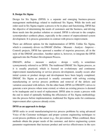
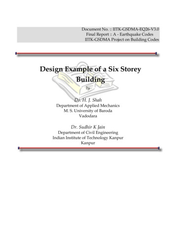
Design Example of a BuildingTable 5 Stability Indices of Different StoreysStoreyStoreyseismicweightWi (kN)Axial loadUuΣPu ΣWi,(kN)(mm)LateralloadHsClassificationQsi(mm)Hu Vi(kN) Pu Δ uH u hs75 5975 5977.234805 0000.0169No-sway66 38111 97812.198605 0000.0340No-sway56 38118 35915.681 1045 0000.0521Sway46 38124 74017.581 2425 0000.0700Sway36 38131 12117.261 3045 0000.0824Sway26 13837 2599.081 3204 1000.0625Sway12 02739 2860.411 3201 1000.0111No-sway1.10.Design of Selected BeamsThe design of one of the exterior beamB2001-B2002-B2003 at level 2 along Xdirection is illustrated here.1.10.1. General requirementsThe flexural members shall fulfil the followinggeneral requirements.(IS 13920; Clause 6.1.2)b 0.3Db 300 0.5 0.3D 600HereHence, ok.(IS 13920; Clause 6.1.3)b 200 mmHere b 300 mm 200 mmHence, ok.(IS 13920; Clause 6.1.4)D Lc4IITK-GSDMA-EQ26-V3.0Here,Lc 7500 – 500 7000 mmD 600 mm 7000mm4Hence, ok.1.10.2. Bending Moments and Shear ForcesThe end moments and end shears for six basicload cases obtained from computer analysis aregiven in Tables 6 and 7. Since earthquake loadalong Z-direction (EZTP and EZTN) induces verysmall moments and shears in these beams orientedalong the X-direction, the same can be neglectedfrom load combinations. Load combinations 6 to9, 14 to 17, and 22 to 25 are thus not consideredfor these beams. Also, the effect of positivetorsion (due to accidental eccentricity) for thesebeams will be more than that of negative torsion.Hence, the combinations 3, 5, 11, 13, 19 and 21will not be considered in design. Thus, thecombinations to be used for the design of thesebeams are 1, 2, 4, 10, 12, 18 and 20.The software employed for analysis will however,check all the combinations for the designmoments and shears. The end moments and endshears for these seven load combinations aregiven in Tables 8 and 9. Highlighted numbers inthese tables indicate maximum values.Page 18
Design Example of a BuildingTo get an overall idea of design moments inFrom the results of computer analysis, momentbeams at various floors, the design moments andenvelopes for B2001 and B2002 are drawn inshears for all beams in frame A-A are given inFigures 4 (a) and 4 (b) for various loadcombinations, viz., the combinations 1, 2,Tables 11 and 12. It may be noted that values of4,10,12,18 and 20. Design moments and shears atlevel 2 in Tables 11 and 12 are given in table 10.various locations for beams B2001-B2002–B2003are given in Table 10.Table 6 End Moments (kNm) for Six Basic Load .6114.5814.7015.4716.31Sign convention: Anti-clockwise moment ( ); Clockwise moment (-)Table 7 End Shears (kN) For Six Basic Load CasesS.No. Load .803.90-3.904.24-4.24Sign convention: ( ) Upward force; (--) Downward forceIITK-GSDMA-EQ26-V3.0Page 19
Design Example of a BuildingTable 8Factored End Moments (kNm) for Load CombinationsCombn Load tRight1[1.5(DL L IL (DL (DL .9DL .51Sign convention: ( ) Anti-clockwise moment; (--) Clockwise momentTable 9 Factored End Shears (kN) for Load CombinationsCombnNo:Load ght1[1.5(DL IL)]189.35210.02266.36266.36210.02189.352[1.2(DL IL EXTP)]78.58240.92149.92276.2695.11224.394[1.2(DL DL EXTP)]254.6988.44289.07131.15270.7072.4318[0.9DL .5EXTP]189.2616.61205.0347.11198.877.00Sign convention: ( ) Upward force; (--) Downward forceIITK-GSDMA-EQ26-V3.0Page 20
Design Example of a Building300Sagging Moment Envelope18202001000M o m e n ts in K N e in mm-20024-300-400Hogging Moment Envelope-500Note: 1, 2, 4,
Design Example of a Building IITK-GSDMA-EQ26-V3.0 Page 3 Example — Seismic Analysis and Design of a Six Storey Building Problem Statement: A six storey building for a commercial complex has plan dimensions as shown in Figure 1. The building is located in