Transcription
User ManualOmniSite ViperVersion 2.0User ManualOmniSite 494 S. Emerson Ave., Suite E, Greenwood, IN 46143www.omnisite.com Telephone: 317-885-6330
VIPERUSER MANUALCONTENTSCHAPTER 1 – INTRODUCTION .51.0 INTRODUCTION .51.1 INTRODUCTION TO THE VIPER .51.2 PURPOSE .61.2.1 Intended Audience . 61.2.2 Typical Product Applications . 6CHAPTER 2 – OVERVIEW .72.1 PRODUCT DESCRIPTION & PRODUCT NUMBERS .72.2 SPECIFICATIONS .82.2.1 Dimensions . 82.2.2 Electrical Specifications . 102.3 COMPONENTS CHECKLIST. 10CHAPTER 3 – USER INTERFACE . 113.1 VIPER INTERFACE . 113.1.1 Display Button Functions . 113.1.2 Display Codes . 133.1.3 Magnetic Key . 143.1.4 Viper Padlock Capabilities . 143.1.5 Power LED . 153.2 POWER ON SELF TEST. 15CHAPTER 4 – VIPER INPUTS . 164.1 DIGITAL ALARM INPUTS . 164.1.1 Inputs 1 & 2 . 164.1.2 Inputs 3,4, 5 Configurations . 164.2 ANALOG (4-20MA) INPUT . 164.2.1 Optional Analog Input . 164.2.2 Analog Input Configuration . 17Page 2Version 2.0.0Questions? Contact OmniSite !www.omnisite.com Telephone: 317-885-6330
VIPERUSER MANUALCHAPTER 5 – WIRING HARNESSES . 185.1 QUICK CONNECT HARNESS . 185.2 ADVANCED HARNESS . 195.3 BATTERY WIRING HARNESS . 195.4 ANALOG INPUT WIRING HARNESS. 195.5 DETERMINING YOUR WIRING HARNESS . 20CHAPTER 6 – INSTALLATION . 216.1 VERIFY CELL SERVICE . 216.2 WIRING PRACTICES . 216.2.1 Connecting Non-Powered Contacts (Quick Connect) . 226.2.2 Advanced/OEM Non-Powered Contacts Wiring . 236.2.3 Advanced/OEM Powered Contacts Wiring . 246.2.4 Wiring 4-20mA Device to Viper Analog Input . 256.2.4 Powering Viper off 10-18VDC . 266.3 MOUNTING OF THE ENCLOSURE OUTSIDE OF A PANEL . 276.4 MOUNTING OF THE ENCLOSURE INSIDE OF A PANEL. 276.4.1 Remote Mounting of antenna . 27CHAPTER 7 – FINAL INSTALLATION PROCEDURES . 287.1 POWERING UNIT ON/OFF . 287.2 PUSH-TO-TEST BUTTON . 287.2.1 Description . 287.2.2 Error Codes . 297.3 VIPER LID PROP . 297.4 INSTALLATION CHECKLIST . 30CHAPTER 8 – PROGRAMMING UNIT . 318.1 GUARDDOG – CALLOUT LIST . 318.2 GUARDDOG – DEVICE SETUP . 368.3 SMS BACKUP . 388.3.1 GuardDog setup . 39CHAPTER 9 – APPENDIX . 419.1 APPENDIX . 419.1.1 Specifications . 419.1.2 Troubleshooting Tips . 429.1.3 Accessory Parts/Repair Parts . 439.1.4 Other OmniSite Products . 43Page 3Version 2.0.0Questions? Contact OmniSite !www.omnisite.com Telephone: 317-885-6330
NOTICE:INSPECT CONTENTS IMMEDIATELY AND FILE CLAIMWITH DELIVERING CARRIER FOR ANY DAMAGE. SAVE THEBOX AND PACKING MATERIAL! YOU ARE RESPONSIBLEFOR DAMAGE TO YOUR UNIT IF RETURNEDIMPROPERLY d WarrantyIf it appears within one (1) year from date of delivery to Purchaser that any products or component parts donot conform exactly to the specifications and physical dimensions referred to herein, and the Purchaser, atits expense, returns the product or component parts to the Seller together with a report of defects, the Sellershall review the inspection report and inspect the items and shall authorize, at its option, either the repair orreplacement of any non-conforming products or component parts, whether on warranty, contract ofnegligence, shall not in any case exceed the amount to be paid by the Seller in obtaining and repair orreplacement of non-conforming products or component parts, and upon expiration of the warranty period, allliability of the Seller shall be terminated. This warranty does not cover damage due to acts of God (fire,flood, lightning, etc.) nor product misuse and accidental damage.Seller shall not be liable for any injury, loss or damage direct or consequential arising out of the use or theability to use the product. This warranty gives specific legal rights. You may have other rights that vary fromstate to state. Some states do not allow the exclusion or limitation or incidental or consequential damages,so that the above limitation of exclusion may not apply to you.***If the faceplate of the Viper is ever removed, the warranty will be void.***Warning:The individual user should take care to determine prior to use whether this device is suitable, adequate orsafe for the use intended. Since individual applications are subject to great variation, the manufacturermakes no representation or warranty as to suitability or fitness of these devices for any specific afety Signal WordsDanger: means if the safety information is not followed, someone will be seriously injured or killed.Warning: means if the safety information is not followed, someone could be seriously injured or killed.Caution: means if the safety information is not followed, someone may be seriously injured or killed.1. To reduce the risk of fire or shock hazard, connect OmniSite RTU directly to a 120 VAC electricalcircuit. Do not use extension cords for permanent installation.2. Cover of OmniSite RTU must be securely closed to prevent water damage and electrical shock.3. Never operate your OmniSite RTU while any part is missing or damaged in any manner.4. To reduce the risk of electrical hazard or damage, do not tilt, jolt or tip RTU while unit is powered-on.5. To reduce the risk of accidental electrical shock, do not touch the electrical terminals or controls withwet hands.6. Note the warning label.Page 4Version 2.0.0Questions? Contact OmniSite !www.omnisite.com Telephone: 317-885-6330
CHAPTER 1 – INTRODUCTION1.0 IntroductionCongratulations – you just bought the best. The OmniSite system provides two-waycommunications using our patented WINGS (Wireless Information Network Gateway Standard)over a cellular network. The low cost of the OmniSite method makes remote monitoring veryaffordable, and allows our devices to operate on GSM networks worldwide. We have the mostcomplete coverage and best reputation in the industry.OmniSite wireless monitoring devices provide a low cost wireless system for remote monitoring,measurement, and data collection anywhere, wherever there is GSM service, worldwide.1.1 Introduction to the ViperThe OmniSite Viper is the latest addition to the OmniSite product line. The Viper is low-cost andover-the-air configurable. This eliminates costly trips to the jobsite. It requires very littlemaintenance and is stand-alone. The Viper has 5 digital inputs and reports any changes. Thisinformation is displayed online on your personal, secure GuardDog account website.The OmniSite Viper is a remote monitoring device that utilizes the cellular network to transmitalarms and runtime data to a central server. This information can then be displayed online forOmniSite customers to view, and notifications can be sent to customers through phone, e-mail,and/or SMS messages.Page 5Version 2.0.0Questions? Contact OmniSite !www.omnisite.com Telephone: 317-885-6330
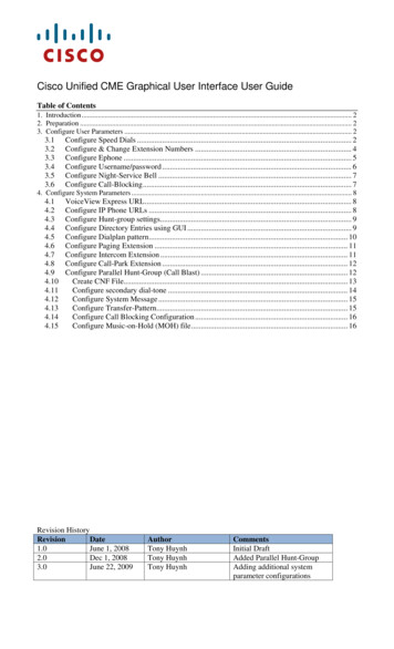
Figure 1. How the Viper gets data to the customer.CHAPTER 1 – INTRODUCTIONFor the Viper to function, it must be installed in an area that has GSM coverage (which should beverified before installation). Once activated, the unit automatically connects to the nearest celltower. Whenever an alarm input changes state, the Viper will transmit this information to thetower, which is then sent through a gateway to the internet, and then to OmniSite’s internetservers. The servers update the Viper’s status on the GuardDog website. Notifications are sentout as well when alarm conditions are met, if the notifications are configured on GuardDog.Over-the-Air (OTA) Configurations are done through the GuardDog website. The Over-the-AirConfigurations can change digital alarm inputs to pump runtimes, change the time delay on eachindividual input, change the time scheduled report time, and configure an analog input. You cansay goodbye to costly trips to the installation location with the new OmniSite Viper!1.2 PurposeThe OmniSite Viper is a low cost, effective Cellular Alarm Monitor that is easy to install and setup. This manual provides the information needed to install the Viper, connect the inputs, andgeneral usage of the product.The main objectives of this guide are to provide: General understanding of operating the OmniSite ViperManufacturing and installation instructionsGeneral understanding of the different wiring harnessesGeneral understanding of the required GuardDog setup1.2.1 Intended AudienceThis manual was written for use by the installer and for use by the end-user of the Viper, to beable to view and understand the Viper.1.3 Typical Product ApplicationsAny control station that has critical circuits that need to be monitored for change of state.Pumping Lift Stations, to monitor well tank levels (using floats), pump runtimes, or other controlor alarm circuits on the pumping station.Monitor door openings, motion detection, or any set of contacts that are critical when alarmed.Page 6Version 2.0.0Questions? Contact OmniSite !www.omnisite.com Telephone: 317-885-6330
CHAPTER 2 – OVERVIEW2.1 Product Description & Product NumbersWhen placing an order with OmniSite for the Viper, use the following product descriptions tospecify your order.Viper Quick Connect KitPart Number: VIPER - KITViper Advanced KitPart Number: VIPER-OEM*Either kit can be equipped with (1) 4-20mA analog input card. If you wish to add this to yourorder, please specify!*For purchasing information, contact OmniSite or your local sales representative.If you require additional accessory parts at a later time, please review our part numbers shown atthe end of this manual for ordering information.Page 7Version 2.0.0Questions? Contact OmniSite !www.omnisite.com Telephone: 317-885-6330
CHAPTER 2 – OVERVIEW2.2 Specifications2.2.1 Dimensions2.632.63Front view ofenclosure withdimensions forOmniSite Viper.8.5369.0606.94Page 8Version 2.0.0Questions? Contact OmniSite !www.omnisite.com Telephone: 317-885-6330
CHAPTER 2 – OVERVIEW2.2.1 Dimensions2.84Side view of enclosure with dimensions for OmniSite Viper.Page 9Version 2.0.0Questions? Contact OmniSite !www.omnisite.com Telephone: 317-885-6330
CHAPTER 2 – OVERVIEW2.2.2 Electrical SpecificationsDescriptionRangePrimary Power - AC98 – 135 VACPrimary Power - DC10 – 18 VDCDigital Inputs12 – 120 VBattery3.9 – 4.3 VDCNotes(Optional) if AC power is not available **AC or DC voltageUse only OmniSite supplied battery** The Quick Connect Kit MUST run off the 98 – 135 VAC primary power!**For Primary Power – DC Current Consumption please see the specifications chapter 9.2.3 Components Checklist:Use the following components checklist to be sure all parts are included in your order. If you aremissing any of the following parts, please contact OmniSite immediately.( ) OmniSite Viper Unit( ) Viper Quick Start Guide( ) ADVANCED or OEM/Quick Connect Wiring Harness( ) Current Sensor (1, 2, or 3)( ) 50 ft High Level Float( ) Magnetic Key( ) OmniSite Sharpie(AVAILABLE ONLINE) Viper Pocket User Manual( ) Viper backup battery with two-prong connector(OPTIONAL) Viper Analog Monitoring DevicePage 10Version 2.0.0Questions? Contact OmniSite !www.omnisite.com Telephone: 317-885-6330
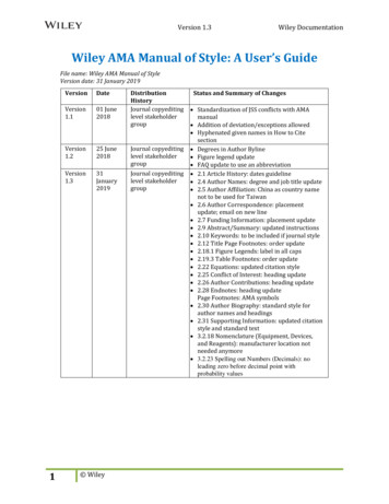
CHAPTER 3 – USER INTERFACE3.1 Viper Interface3.1.1 Display Button FunctionThe Viper has a two digit LED display to allow the user to get basic information from the unit.The display enters user mode when the button directly below the display is pressed (Check Statusbutton). User mode allows the user to view the status of the inputs, read the received cellularsignal strength, or see the firmware version that the unit is running. Each time the push button ispressed, the display advances to the next piece of information.The user mode menu flow is shown below:Figure 2: Display Menu FlowThe unit will display “- -“ after it has been in the idle state for more than one minute. After atotal of five minutes, the display will shut off. It will turn on once again if the status of an inputchanges, causing the unit to transmit or if the display button is pressed.Input StatusWhen viewing an input status, the display will show the input number and the open/closed statusin an alternating fashion. The input number is shown by “n#”, where # is the input number. Forexample, “n3” means that the status of input 3 is being displayed. The status will show either“OP” for open or “CL” for closed. The unit will advance to the next input each time the button ispressed.Page 11Version 2.0.0Questions? Contact OmniSite !www.omnisite.com Telephone: 317-885-6330
CHAPTER 3 – USER INTERFACESignal StrengthThe signal strength of the unit can be checked by pressing the button beneath the display untilthe RSSI (Received Signal Strength Indicator) “ ” symbol is shown. This can be found afterscrolling through all of the input status screens. The Viper will alternate between the RSSI symboland the current signal strength. The following table shows how to read the signal.Signal Reading0-34-78 – 1213 - 1718 or GreaterSignal StrengthUnacceptableBadModerateGoodExcellentIf you are experiencing unusable, bad, or OK signal strength, please contact OmniSite forsolutions.FirmwareThe final page of the user mode shows the firmware that the Viper is currently running. Thisscreen will alternate between “F-“ and the firmware revision.Page 12Version 2.0.0Questions? Contact OmniSite !www.omnisite.com Telephone: 317-885-6330
CHAPTER 3 –
OmniSite wireless monitoring devices provide a low cost wireless system for remote monitoring, measurement, and data collection anywhere, wherever there is GSM service, worldwide. 1.1 Introduction to the Viper The OmniSite Viper is the latest addition to the OmniSite product line. The Viper is low-cost and over-the-air configurable.File Size: 2MBPage Count: 43People also search forgd viper installation manualsecure terminal equipment user's guideg&w viper manualviper phone armysectera viper phone administrator manualsectera viper phone how to untampered