Transcription
Part 1Basic principlesof fluid mechanicsand physicalthermodynamics.
Introduction to Fluid MechanicsMalcolm J. McPhersonChapter 2. Introduction to Fluid Mechanics2.1 INTRODUCTION . 12.1.1 The concept of a fluid. 12.1.2 Volume flow, Mass flow and the Continuity Equation. 32.2 FLUID PRESSURE. 32.2.1 The cause of fluid pressure. 32.2.2 Pressure head. 42.2.3 Atmospheric pressure and gauge pressure. 52.2.4. Measurement of air pressure. 52.2.4.1. Barometers. 52.2.4.2. Differential pressure instruments . 62.3 FLUIDS IN MOTION . 82.3.1. Bernoulli's equation for ideal fluids . 8Kinetic energy. 8Potential energy . 9Flow work . 92.3.2. Static, total and velocity pressures. . 112.3.3. Viscosity . 122.3.4. Laminar and turbulent flow. Reynolds Number. 142.3.5. Frictional losses in laminar flow, Poiseuille's Equation. 162.3.6. Frictional losses in turbulent flow. 222.3.6.1. The Chézy-Darcy Equation . 222.3.6.2. The coefficient of friction, f. . 252.3.6.3. Equations describing f - Re relationships. 27Laminar Flow . 27Smooth pipe turbulent curve . 28Rough pipes . 29Bibliography . 312.1 INTRODUCTION2.1.1 The concept of a fluidA fluid is a substance in which the constituent molecules are free to move relative to each other.Conversely, in a solid, the relative positions of molecules remain essentially fixed under nondestructive conditions of temperature and pressure. While these definitions classify matter into fluidsand solids, the fluids sub-divide further into liquid and gases.Molecules of any substance exhibit at least two types of forces; an attractive force that diminisheswith the square of the distance between molecules, and a force of repulsion that becomes strongwhen molecules come very close together. In solids, the force of attraction is so dominant that themolecules remain essentially fixed in position while the resisting force of repulsion prevents themfrom collapsing into each other. However, if heat is supplied to the solid, the energy is absorbedinternally causing the molecules to vibrate with increasing amplitude. If that vibration becomessufficiently violent, then the bonds of attraction will be broken. Molecules will then be free to move inrelation to each other - the solid melts to become a liquid.2-1
Introduction to Fluid MechanicsMalcolm J. McPhersonWhen two moving molecules in a fluid converge on each other, actual collision is averted (at normaltemperatures and velocities) because of the strong force of repulsion at short distances. Themolecules behave as near perfectly elastic spheres, rebounding from each other or from the walls ofthe vessel. Nevertheless, in a liquid, the molecules remain sufficiently close together that the force ofattraction maintains some coherence within the substance. Water poured into a vessel will assumethe shape of that vessel but may not fill it. There will be a distinct interface (surface) between thewater and the air or vapour above it. The mutual attraction between the water molecules is greaterthan that between a water molecule and molecules of the adjacent gas. Hence, the water remains inthe vessel except for a few exceptional molecules that momentarily gain sufficient kinetic energy toescape through the interface (slow evaporation).However, if heat continues to be supplied to the liquid then that energy is absorbed as an increase inthe velocity of the molecules. The rising temperature of the liquid is, in fact, a measure of theinternal kinetic energy of the molecules. At some critical temperature, depending upon the appliedpressure, the velocity of the molecules becomes so great that the forces of attraction are no longersufficient to hold those molecules together as a discrete liquid. They separate to much greaterdistances apart, form bubbles of vapour and burst through the surface to mix with the air or othergases above. This is, of course, the common phenomenon of boiling or rapid evaporation. The liquidis converted into gas.The molecules of a gas are identical to those of the liquid from which it evaporated. However, thosemolecules are now so far apart, and moving with such high velocity, that the forces of attraction arerelatively small. The fluid can no longer maintain the coherence of a liquid. A gas will expand to fillany closed vessel within which it is contained.The molecular spacing gives rise to distinct differences between the properties of liquids and gases.Three of these are, first, that the volume of gas with its large intermolecular spacing will be muchgreater than the same mass of liquid from which it evaporated. Hence, the density of gases(mass/volume) is much lower than that of liquids. Second, if pressure is applied to a liquid, then thestrong forces of repulsion at small intermolecular distances offer such a high resistance that thevolume of the liquid changes very little. For practical purposes most liquids (but not all) may beregarded as incompressible. On the other hand, the far greater distances between molecules in agas allow the molecules to be more easily pushed closer together when subjected to compression.Gases, then, are compressible fluids.A third difference is that when liquids of differing densities are mixed in a vessel, they will separateout into discrete layers by gravitational settlement with the densest liquid at the bottom. This is nottrue of gases. In this case, layering of the gases will take place only while the constituent gasesremain unmixed (for example, see Methane Layering, Section 12.4.2). If, however, the gasesbecome mixed into a homogenous blend, then the relatively high molecular velocities and largeintermolecular distances prevent the gases from separating out by gravitational settlement. Theinternal molecular energy provides an effective continuous mixing process.Subsurface ventilation engineers need to be aware of the properties of both liquids and gases. Inthis chapter, we shall confine ourselves to incompressible fluids. Why is this useful when we are wellaware that a ventilation system is concerned primarily with air, a mixture of gases and, therefore,compressible? The answer is that in a majority of mines and other subsurface facilities, the ranges oftemperature and pressure are such that the variation in air density is fairly limited. Airflowmeasurements in mines are normally made to within 5 per cent accuracy. A 5 per cent change in airdensity occurs by moving through a vertical elevation of some 500 metres in the gravitational field atthe surface of the earth. Hence, the assumption of incompressible flow with its simpler analyticalrelationships gives acceptable accuracy in most cases. For the deeper and (usually) hotter facilities,the effects of pressure and temperature on air density should be taken into account throughthermodynamic analyses if a good standard of accuracy is to be attained. The principles of physicalsteady-flow thermodynamics are introduced in Chapter 3.2-2
Introduction to Fluid MechanicsMalcolm J. McPherson2.1.2 Volume flow, Mass flow and the Continuity EquationMost measurements of airflow in ventilation systems are based on the volume of air (m3) that passesthrough a given cross section of a duct or airway in unit time (1 second). The units of volume flow, Q,are, therefore, m3/s. However, for accurate analyses when density variations are to be taken intoaccount, it is preferable to work in terms of mass flow - that is, the mass of air (kg) passing throughthe cross section in 1 second. The units of mass flow, M, are then kg/s.The relationship between volume flow and mass flow follows directly from the definition of density, ρ,kgmassρ (2.1)volumem3andmass flow Mkg sρ volume flow Qs m3giving M Q ρ kg/s(2.2)In any continuous duct or airway, the mass flows passing through all cross sections along its lengthare equal, provided that the system is at steady state and there are no inflows or outflows of air orother gases between the two ends. If these conditions are met thenM Q ρ constantkg/s(2.3)This is the simplest form of the Continuity Equation. It can, however, be written in other ways. Acommon method of measuring volume flow is to determine the mean velocity of air, u, over a givencross section, then multiply by the area of that cross-section, A, (Chapter 6):m3mm 2 orssThen the continuity equation becomesQ uA(2.4)M ρ u A constant kg/s(2.5)As indicated in the preceding subsection, we can achieve acceptable accuracy in most situationswithin ventilation systems by assuming a constant density. The continuity equation then simplifiesback toQ uA constantm3/s(2.6)This shows that for steady-state and constant density airflow in a continuous airway, the velocity ofthe air varies inversely with cross sectional area.2.2 FLUID PRESSURE2.2.1 The cause of fluid pressureSection 2.1.1 described the dynamic behaviour of molecules in a liquid or gas. When a moleculerebounds from any confining boundary, a force equal to the rate of change of momentum of thatmolecule is exerted upon the boundary. If the area of the solid/fluid boundary is large compared tothe average distance between molecular collisions then the statistical effect will be to give a uniformforce distributed over that boundary. This is the case in most situations of importance in subsurfaceventilation engineering.2-3
Introduction to Fluid MechanicsMalcolm J. McPhersonTwo further consequences arise from the bombardment of a very large number of molecules on asurface, each molecule behaving essentially as a perfectly elastic sphere. First, the force exerted bya static fluid will always be normal to the surface. We shall discover later that the situation is ratherdifferent when the dynamic forces of a moving fluid stream are considered (Section 2.3). Secondly,at any point within a static fluid, the pressure is the same in all directions. Hence, static pressure is ascalar rather than a vector quantity.Pressure is sometimes carelessly confused with force or thrust. The quantitative definition ofpressure, P, is clear and simpleP ForceAreaN(2.7)m2In the SI system of units, force is measured in Newtons (N) and area in square metres. The resultingunit of pressure, the N/m2, is usually called a Pascal (Pa) after the French philosopher, BlaisePascal (1623-1662).2.2.2 Pressure headIf a liquid of density ρ is poured into a vertical tube of cross-sectional area, A, until the level reachesa height h, the volume of liquid isvolume h Am3Then from the definition of density (mass/volume), the mass of the liquid ismass volume x density hAρkgThe weight of the liquid will exert a force, F, on the base of the tube equal tomass x gravitational acceleration (g)F hAρgNBut as pressure force/area, the pressure on the base of the tube isP F ρ ghANm2or Pa(2.8)Hence, if the density of the liquid is known, and assuming a constant value for g, then the pressuremay be quoted in terms of h, the head of liquid. This concept is used in liquid type manometers(Section 2.2.4) which, although in declining use, are likely to be retained for many purposes owing totheir simplicity.Equation (2.8) can also be used for air and other gases. In this case, it should be remembered thatthe density will vary with height. A mean value may be used with little loss in accuracy for most mineshafts. However, here again, it is recommended that the more precise methodologies ofthermodynamics be employed for elevation differences of more than 500 m.2-4
Introduction to Fluid MechanicsMalcolm J. McPherson2.2.3 Atmospheric pressure and gauge pressureThe blanket of air that shrouds the earth extends to approximately 40 km above the surface. At thatheight, its pressure and density tend towards zero. As we descend towards the earth, the number ofmolecules per unit volume increases, compressed by the weight of the air above. Hence, thepressure of the atmosphere also increases. However, the pressure at any point in the loweratmosphere is influenced not only by the column of air above it but also by the action of convection,wind currents and variations in temperature and water vapour content. Atmospheric pressure nearthe surface, therefore, varies with both place and time. At the surface of the earth, atmosphericpressure is of the order of 100 000 Pa. For practical reference this is often translated into 100 kPaalthough the basic SI units should always be used in calculations. Older units used in meteorologyfor atmospheric pressure are the bar (105 Pa) and the millibar (100 Pa).For comparative purposes, reference is often made to standard atmospheric pressure. This is thepressure that will support a 0.760 m column of mercury having a density of 13.5951 x 10³ kg/m3 in astandard earth gravitational field of 9.8066 m/s2.Then from equation (2.8)One Standard Atmosphere ρ x g x h 13.5951 x 103 x 9.8066 x 0.760 101.324 x 10³or101.324PakPa.The measurement of variations in atmospheric pressure is important during ventilation surveys(Chapter 6), for psychrometric measurements (Chapter 14), and also for predicting the emission ofstored gases into a subsurface ventilation system (Chapter 12). However, for many purposes, it isnecessary to measure differences in pressure. One common example is the difference between thepressure within a system such as a duct and the exterior atmosphere pressure. This is referred to asgauge pressure.Absolute pressure Atmospheric pressure gauge pressure(2.9)If the pressure within the system is below that of the local ambient atmospheric pressure then thenegative gauge pressure is often termed the suction pressure or vacuum and the sign ignored.Care should be taken when using equation 2.9 as the gauge pressure may be positive or negative.However, the absolute pressure is always positive. Although many quoted measurements arepressure differences, it is the absolute pressures that are used in thermodynamic calculations. Wemust not forget to convert when necessary.2.2.4. Measurement of air pressure.2.2.4.1. BarometersEquation (2.8) showed that the pressure at the bottom of a column of liquid is equal to the product ofthe head (height) of the liquid, its density and the local value of gravitational acceleration. Thisprinciple was employed by Evangelista Torricelli (1608-1647), the Italian who invented the mercurybarometer in 1643. Torricelli poured mercury into a glass tube, about one metre in length, closed atone end, and upturned the tube so that the open end dipped into a bowl of mercury. The level in thetube would then fall until the column of mercury, h, produced a pressure at the base that justbalanced the atmospheric pressure acting on the open surface of mercury in the bowl.2-5
Introduction to Fluid MechanicsMalcolm J. McPhersonThe atmospheric pressure could then be calculated as (see equation (2.8) )P ρghPawhere, in this case, ρ is the density of mercury.Modern versions of the Torricelli instrument are still used as standards against which other types ofbarometer may be calibrated. Barometric (atmospheric) pressures are commonly quoted inmillimetres (or inches) of mercury. However, for precise work, equation (2.8) should be employedusing the density of mercury corresponding to its current temperature. Accurate mercury barometershave a thermometer attached to the stem of the instrument for this purpose and a sliding micrometerto assist in reading the precise height of the column. Furthermore, and again for accurate work, thelocal value of gravitational acceleration should be ascertained as this depends upon latitude andaltitude. The space above the mercury in the barometer will not be a perfect vacuum as it containsmercury vapour. However, this exerts a pressure of less than 0.00016 kPa at 20 ºC and is quitenegligible compared with the surface atmospheric pressure of near 100 kPa. This, coupled with thefact that the high density of mercury produces a barometer of reasonable length, explains whymercury rather than any other liquid is used. A water barometer would need to be about 10.5m inheight.Owing to their fragility and slowness in reacting to temperature changes, mercury barometers areunsuitable for underground surveys . An aneroid barometer consists of a closed vessel which hasbeen evacuated to a near perfect vacuum. One or more elements of the vessel are flexible. Thesemay take the form of a flexing diaphragm, or the vessel itself may be shaped as a helical or spiralspring. The near zero pressure within the vessel remains constant. However, as the surroundingatmospheric pressure varies, the appropriate element of the vessel will flex. The movement may betransmitted mechanically, magnetically or electrically to an indicator and/or recorder.Low cost aneroid barometers may be purchased for domestic or sporting use. Most altimeters are, infact, aneroid barometers calibrated in metres (or feet) head of air. For the high accuracy required inventilation surveys (Chapter 6) precision aneroid barometers are available.Another principle that can be employed in pressure transducers, including barometers, is thepiezoelectric property of quartz. The natural frequency of a quartz beam varies with the appliedpressure. As electrical frequency can be measured with great precision, this allows the pressure tobe determined with good accuracy.2.2.4.2. Differential pressure instrumentsDifferences in air pressure that need to be measured frequently in subsurface ventilationengineering rarely exceed 7 or 8 kPa and are often of the order of only a few Pascals. The traditionalinstrument for such low pressure differences is the manometer. This relies upon the displacement ofliquid to produce a column, or head, that balances the differential pressure being measured. Themost rudimentary manometer is the simple glass U tube containing water, mercury or other liquid. Apressure difference applied across the ends of the tube causes the liquid levels in the two limbs tobe displaced in opposite directions. A scale is used to measure the vertical distance between thelevels and equation (2.8) used to calculate the required pressure differential. Owing to the pastwidespread use of water manometers, the millimetre (or inch) of water column came to be usedcommonly as a measure of small pressure differentials, much as a head of mercury has been usedfor atmospheric pressures. However, it suffers from the same disadvantages in that it is not aprimary unit but depends upon the liquid density and local gravitational acceleration.When a liquid other than water is used, the linear scale may be increased or decreased, dependentupon the density of the liquid, so that it still reads directly in head of water. A pressure head in one2-6
Introduction to Fluid MechanicsMalcolm J. McPhersonfluid can be converted to a head in any other fluid provided that the ratio of the two densities isknown.p ρ 1 g h1orh2 ρ1hρ2 1 ρ 2 g h2mPa(2.10)For high precision, the temperature of the liquid in a manometer should be obtained and thecorresponding density determined. Equation (2.10) is then used to correct the reading, h1 where ρ1 isthe actual liquid density and ρ2 is the density at which the scale is calibrated.Many variations of the manometer have been produced. Inclining one limb of the U tube shortens itspracticable range but gives greater accuracy of reading. Careful levelling of inclined manometers isrequired and they are no longer used in subsurface pressure surveys. Some models have one limbof the U tube enlarged into a water reservoir. The liquid level in the reservoir changes only slightlycompared with the balancing narrow tube. In the direct lift manometer, the reservoir is connected byflexible tubing to a short sight-glass of variable inclination which may be raised or lowered against agraduated scale. This manipulation enables the meniscus to be adjusted to a fixed mark on thesight-glass. Hence the level in the reservoir remains unchanged. The addition of a micrometer scalegives this instrument both a good range and high accuracy.One of the problems in some water manometers is a misformed meniscus, particularly if theinclination of the tube is less than 5 degrees from the horizontal. This difficulty may be overcome byemploying a light oil, or other liquid that has good wetting properties on glass. Alternatively, the twolimbs may be made large enough in diameter to give horizontal liquid surfaces whose position canbe sensed electronically or by touch probes adjusted through micrometers.U tube manometers, or water gauges as they are commonly known, may feature as part of thepermanent instrumentation of main and booster fans. Provided that the connections are kept firmand clean, there is little that can go wrong with these devices. Compact and portable inclined gaugesare available for rapid readings of pressure differences across doors and stoppings in undergroundventilation systems. However, in modern pressure surveying (Chapter 6) manometers have beenreplaced by the diaphragm gauge. This instrument consists essentially of a flexible diaphragm,across which is applied the differential pressure. The strain induced in the diaphragm is sensedelectrically, mechanically or by magnetic means and transmitted to a visual indicator or recorder.In addition to its portability and rapid reaction, the diaphragm gauge has many advantages for thesubsurface ventilation engineer. First, it reflects directly a true pressure (force/area) rather thanindirectly through a liquid medium. Secondly, it reacts relatively quickly to changes in temperatureand does not require precise levelling. Thirdly, diaphragm gauges can be manufactured over a widevariety of ranges. A ventilation survey team may typically carry gauges ranging from 0 - 100 Pa to 0 5 kPa (or to encompass the value of the highest fan pressure in the system). One disadvantage ofthe diaphragm gauge is that its calibration may change with time and usage. Re-calibration against alaboratory precision manometer is recommended prior to an important survey.Other appliances are used occasionally for differential pressures in subsurface pressure surveys.Piezoelectric instruments are likely to increase in popularity. The aerostat principle eliminates theneed for tubing between the two measurement points and leads to a type of differential barometer. Inthis instrument, a closed and rigid air vessel is maintained at a constant temperature and isconnected to the outside atmospheres via a manometer or diaphragm gauge. As the inside of thevessel remains at near constant pressure, any variations in atmospheric pressure cause a reactionon the manometer or gauge. Instruments based on this principle require independent calibration asslight movements of the diaphragm or liquid in the manometer result in the inside pressure notremaining truly constant.2-7
Introduction to Fluid MechanicsMalcolm J. McPherson2.3 FLUIDS IN MOTION2.3.1. Bernoulli's equation for ideal fluidsAs a fluid stream passes through a pipe, duct or other continuous opening, there will, in general, bechanges in its velocity, elevation and pressure. In order to follow such changes it is useful to identifythe differing forms of energy contained within a given mass of the fluid. For the time being, we willconsider that the fluid is ideal; that is, it has no viscosity and proceeds along the pipe with no shearforces and no frictional losses. Secondly, we will ignore any thermal effects and consider mechanicalenergy only.Suppose we have a mass, m, of fluid moving at velocity, u, at an elevation, Z, and a barometricpressure P. There are three forms of mechanical energy that we need to consider. In each case, weshall quantify the relevant term by assessing how much work we would have to do in order to raisethat energy quantity from zero to its actual value in the pipe, duct or airway.Kinetic energyIf we commence with the mass, m, at rest and accelerate it to velocity u in t seconds by applying aconstant force F, then the acceleration will be uniform and the mean velocity is0 uu 22msThendistance travelled mean velocity x time ut2mFurthermore, the acceleration is defined asincrease in velocityu timetm / s2The force is given byF mass x acceleration mutNand the work done to accelerate from rest to velocity u isWD force x distanceuux t2t2u m2Nm mNm or J(2.11)The kinetic energy of the mass m is, therefore, m u2/2 Joules.2-8
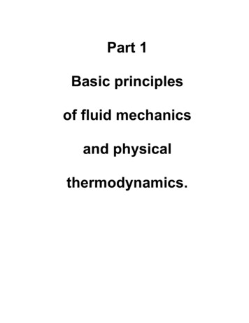
Introduction to Fluid MechanicsMalcolm J. McPhersonPotential energyAny base elevation may be used as the datum for potential energy. In most circumstances ofunderground ventilation engineering, it is differences in elevation that are important. If our mass m islocated on the base datum then it will have a potential energy of zero relative to that datum. We thenexert an upward force, F, sufficient to counteract the effect of gravity.F mass x acceleration mgNwhere g is the gravitational acceleration.In moving upward to the final elevation of Z metres above the datum, the work done isWD Force x distance mgZJoules(2.12)This gives the potential energy of the mass at elevation Z.Flow workSuppose we have a horizontal pipe, open at both ends and of cross sectional area A as shown inFigure 2.1. We wish to insert a plug of fluid, volume v and mass m into the pipe. However, even inthe absence of friction, there is a resistance due to the pressure of the fluid, P, that already exists inthe pipe. Hence, we must exert a force, F, on the plug of fluid to overcome that resisting pressure.Our intent is to find the work done on the plug of fluid in order to move it a distance s into the pipe.sFPvAFigure 2.1 Flow work done on a fluid entering a pipeThe force, F, must balance the pressure, P, which is distributed over the area, A.F PANWork done force x distance PAsJ or JoulesHowever, the product As is the swept volume v, givingWD P vNow, by definition, the density ismρ vormv kgm3ρ2-9
Introduction to Fluid MechanicsMalcolm J. McPhersonHence, the work done in moving the plug of fluid into the pipe isWD orPmJρ(2.13)P/ρ Joules per kilogram.As fluid continues to be inserted into the pipe to produce a continuous flow, then each individualplug must have this amount of work done on it. That energy is retained within the fluid stream and isknown as the flow work. The appearance of pressure, P, within the expression for flow work hasresulted in the term sometimes being labelled "pressure energy". This is very misleading as flowwork is entirely different to the "elastic energy" stored when a closed vessel of fluid is compressed.Some authorities also object to the term "flow work" and have suggested "convected energy" or,simply, the "Pv work". Note that in Figure 2.1 the pipe is open at both ends. Hence the pressure, P,inside the pipe does not change with time (the fluid is not compressed) when plugs of fluid continueto be inserted in a frictionless manner. When the fluid exits the system, it will carry kinetic andpotential energy, and the corresponding flow work with it.Now we are in a position to quantify the total mechanical energy of our mass of fluid, m. Fromexpressions (2.11, 2.12 and 2.13)total mechanicalenergy kineticenergy mu 22 potentialenergymZ gflow work mPρJ(2.14)If no mechanical energy is added to or subtracted from the fluid during its traverse through the pipe,duct or airway, and in the absence of frictional effects, the total mechanical energy must remainconstant throughout the airway. Then equation (2.14) becomes u 2P m Zg
A fluid is a substance in which the constituent molecules are free to move relative to each other. Conversely, in a solid, the relative positions of molecules remain essentially fixed under non- . Introduction to Fluid Mechanics Malcolm J. McPherson 2 - 3 2.1.2 Volume flow, Mass flow and the Continuity Equation Most measurements .