Transcription
EPV200 Portable VentilatorBattery Powered VentilatorWith Oxygen Source RequiredPatent Pending1720 Sublette Avenue St. Louis, MO 63110 USA314-771-2400 800-444-3954 FAX: 800-477-7701www.alliedhpi.comS168-570-001 REV. A
Table of ptionProduct DescriptionProduct Intended UseExplanation of WarningsExplanation of AbbreviationsSpecificationsFeaturesOperating the VentilatorAlarmsBattery ReplacementCleaningMaintenance and ScheduleCheck-out ProcedureAccessoriesWarrantyOxygen Cylinder Depletion TimesSymbolsApplicable StandardsApproximate Settings Based on Patient HeightAttaching EPV200 to EquipmentPage2222345-7899 - 1010 - 1112131314 - 15151617 - 1819Model: EPV200 - Emergency Portable Ventilator with Assist Control1
1Product DescriptionThe EPV200 is an internal battery powered, electronically controlled, portable ventilatorthat requires a 50 psi oxygen source to operate. The EPV200 has selectable tidalvolumes, BPM and inspiratory times based on the intended patient’s respiratoryrequirements.2Product Intended UseThe EPV200 is intended to be used as an electronically controlled gas poweredemergency ventilator to provide emergency respiratory support by means of a facemask or tube inserted into the patient’s airway. This ventilator is intended for use onpatients weighing greater than 20 kg (44 lbs). This ventilator is intended to be used inthe environments associated with emergency medical services (EMS), inter-hospitaltransport and hospital facility usage. This ventilator is intended to be used intemperatures of -9 to 50 C (15 to 122 F) and 5% - 95% relative humidity, noncondensing.Biocompatibility testing has proven this ventilator to be safe for periods up to 14 days ofcontinuous use. Results beyond this length of time are not known.CAUTION: Federal law restricts this device to sale by or on the order of aphysician.CAUTION: The EPV200 should not be used on children with a weight of 20 kg(44 lbs) or less.3Explanation of WarningsWarning: Potential injury to the patient or operator exists.Caution: Potential damage to the ventilator, breathing circuit or other equipment mayresult.Warnings and cautions should be read and understood before operating the ventilator.4Explanation of AbbreviationsTvBPMItpsicm H2OkPamlLPMmmLEDCPRHPARHTidal VolumeBreaths per MinuteInspiratory TimePounds per Square InchCentimeters of WaterKilopascalMillilitersLiters Per MinuteMillimetersLight Emitting DiodeCardio Pulmonary ResuscitationHigh Pressure AlarmRelative Humidity2
5SpecificationsA.B.Gas Supply Pressure: 280 kPa (40.6 psi) to 600 kPa (87 psi) oxygen DISSBreaths Per Minute (BPM): Accuracy: 10%BPM Range: 1 second inspiratory time 0 and 5 to 30BPM Range: 2 second inspiratory time 0 and 5 to 20Tidal Volume (Tv): Accuracy: 10% with 100% oxygenTidal volume range 1 second inspiratory time 200 ml to 600 mlTidal volume range 2 second inspiratory time 400 ml to 1200 mlInspiratory Time (It): Accuracy: 10%1 second or 2 second selectionSafety Pressure Relief: Fixed at a maximum of 60 cm H2OLow Source Gas Alarm: Activates at 275 to 241 kPa (40 to 35 psi) sourcepressure.High Airway Pressure Alarm Electronic: Activates at 45 cm H2O.Alarm sound level is greater than 58 decibels.Breath Delivery Alarm: Activates if the airway pressure does not goabove 9 cm H2O during a span of 15 seconds, or if a spontaneous breath isdetected.Battery Life: Greater than 48 hours at room temperature (10 BPM and2 seconds It)Oxygen Inlet Filter: 65 micron sintered bronzeLeakage: The unit shall be designed so that pressurized oxygen is not allowedto leak through any seals or fittings.Gauge: 0-99 cm H2O accuracy 5% or 1 cm H2O, whichever is greaterInspiratory and Expiratory Resistance: 5 cm H2O (.5kPa) maximumInadvertent PEEP: 2 cm H2OInadvertent Continuing Expiratory Pressure: 2 cm H2ODead Space: 5.5% of minimum tidal volumeWeight: 1.4 kg (3.1 lbs.) with batteriesSize: 3.5 x 7.0 x 9.3 (88.9 x 177.8 x 236.2 mm)Operating Conditions: -9 to 50 C (15 to 122 F) 5% - 95% RH non condensingStorage Conditions: -40 to 60 C (-40 to 140 F) 5% - 95% RH non condensingShipping Conditions: -40 to 60 C (-40 to 140 F) 5% - 95% RH non condensingBreathing mode: Assist Control with 2 cm H2O required to trigger aspontaneous ex Free: This product does not contain Latex.3
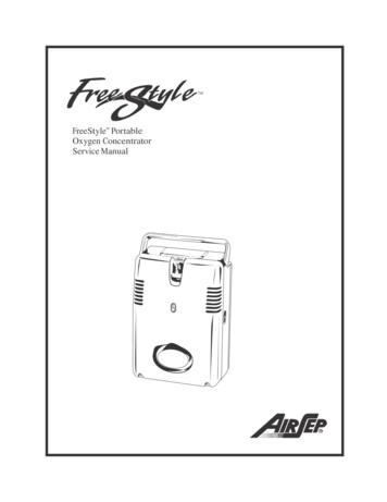
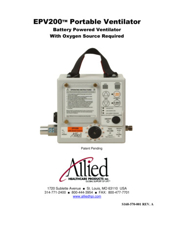
6Features31475552121191051365845515Item #1234567DescriptionTidal Volume ControlInspiratory Time ControlBPM ControlOxygen InletAirway Pressure DisplayPower On/Off SwitchItem #8910111213Battery Compartment144DescriptionAnti-Suffocation ValvePatient Circuit ConnectionHigh Airway Pressure AlarmLow Source Gas AlarmLow Battery AlarmBreath Delivery Alarm ifFlashingBPM Display
7Operating the VentilatorWarning: This device should be operated only by qualified personnelunder approved medical direction.Warning: Use only as directed. Improper usage or unauthorizedmodification of this product may result in user or patient injury.Warning: Unit is not MRI compatible.Warning: Not for use in a toxic environment or in the presence offlammable anesthetics. Connect to an oxygen source:Located on the right side of the ventilator and marked with text is a diameter indexsafety system (DISS) fitting. Connect a 50 psi oxygen source with a minimum of 40LPM flow capacity to this fitting. The unit comes with a single use supply hose made ofPVC. A rubber reusable hose may be purchased and is recommended. Seeaccessories.Warning: Proper tidal volumes may not be provided with a gas sourcenot meeting the specified requirements on page 4.Warning: This device operates with medical gases under pressure,including oxygen. Do not use this device while smoking or near openflames or flammable materials.Caution: In order to provide optimal performance, check all gassupplies to assure that only clean, dry gas that is free of contaminantsand/or liquids is used.The gas source may also be a high flow air/oxygen blend meeting the flow and pressurerequirements. Selectthe proper inspiratory time:Press the ON/OFF button to activate the unit. The EPV200 has the options of a2 second inspiratory time (this is used on adults with tidal volume requirements of morethan 600 ml) and a 1 second inspiratory time (this is used on children or adults). Pushthe appropriate Inspiratory Time button and a green LED will show the selectedinspiratory time. Select the desired breaths per minute (BPM):The EPV200 has a BPM range of 0 and 5 to 20 with a 2 second inspiratory time, and aBPM range of 0 and 5 to 30 with a 1 second inspiratory time. Use the up and downarrows above or below the text “BPM” to set the desired BPM. The BPM setting will bedisplayed in the window above the selection arrows. The 0 BPM setting is used whenthe patient is breathing spontaneously.The American Heart Association Guidelines 2005 recommend a BPM rate of 8 to 12 foran adult and 12 to 20 for a child. These are recommendations. Physician or medicaldirector instructions should always be followed.5
Select the desired tidal volume (Tv):Turn the tidal volume knob to the desired tidal volume setting. The flow to the patient isdifferent for each tidal volume.Tidal Volume SettingApproximate Flow(LPM)It 1 second It 2 8.831.233.636 Verify the pressure relief setting:This unit has a factory set pressure relief setting of less than 60 cm H2O. The 60 cmH2O setting is a maximum, regardless of vent settings. The pressure relief setting willvary slightly with tidal volume setting. Lower tidal volumes will have a slightly lowerpressure relief point. Always verify the relief pressure after the vent settings have beenselected. To check the actual relief pressure, block the end of the ventilator breathingcircuit and observe the reading on the airway pressure gauge. This will be themaximum airway pressure. You should hear an audible alarm and see a flashing lightas this maximum pressure is reached.Warning: Preset tidal volumes may not be delivered when themaximum pressure limit is reached. Inspiratory times will remainconstant. However, no additional tidal volume will be delivered afterthe pressure limit is reached. Connect the patient breathing circuit:Located on the left side of the unit is a 22 mm connection for a patient breathing circuit.The patient breathing circuit has been designed to fit with an oxygen mask (22 mmoutside diameter) or an endotracheal tube (15 mm inside diameter). Install thecorrugated tubing over the connector so that it is on securely. Follow the establishedguidelines for maintaining the patient’s airway.6
Verify the patient is receiving good ventilation:Once the patient is connected to the ventilator, the patient should be observed to makesure he has adequate chest rise and fall. The chest rise should be even and shouldreturn to a normal position. If the patient does not have adequate chest rise, check thetidal volume setting and patient connections and examine the patient for a possibleobstruction of the airway or other injury. The patient should be monitored to make surehe is receiving proper ventilation.The airway pressure gauge should be observed to make sure the patient is receivingadequate positive pressure ventilation. If the gauge reading is low during the delivery ofa breath and the chest rise is also low, check the tidal volume setting and patientconnections and examine the patient for a possible obstruction of the airway or otherinjury. The gauge reading should also be observed to make sure it is not too high.Common numbers used in practice are a maximum of 20 cm H2O for an unprotectedairway and 30 cm H2O for a protected airway. Higher pressures may be required basedon the patient’s condition. Physician instructions should always be followed. A highreading with a pressure limit alarm may indicate a blocked airway or a stiff lung. If youare using a PEEP valve with the ventilator circuit, the PEEP pressure will not bedisplayed on the gauge (Airway Pressure Display). Spontaneous breathing by the patient:Should the patient begin to breathe spontaneously, the EPV200 will sense this breathand deliver the set tidal volume at the corresponding inspiratory time. The breath timingwill be reset based on the selected BPM rate. For example, if 10 BPM was selected,the next breath will be delivered 6 seconds after the start of the spontaneous breath.The gas flow rate to the patient during a spontaneous breath is based on the tidalvolume selection as shown in the table on page 7. Should the patient demand exceedthe gas flow rate, the additional demand will be supplied by the ambient air. Ambient airis pulled in through an anti-suffocation valve located in the breathing circuit connectionfitting.Warning: Do not cover or block the anti-suffocation valve.Warning: Should a mechanical problem develop or the patient appearsto be experiencing difficulty breathing while connected to the unit,disconnect the unit immediately and ventilate by other means. Cold temperature operation:Operating time will be significantly reduced if the batteries are stored at lowtemperatures. At 15 F (-9 C) the battery life will be approximately 9 hours (10 BPM and2 second It) before the low battery indicator turns on. The low battery indicator will stillgive about a 2 hour low battery warning. Batteries should be replaced when the lowbattery indicator appears, as run times are reduced at low temperatures. When the unitstops operating you will receive a breath delivery alarm.Warning: Batteries stored at temperatures below 15 F (-9 C) may nothave enough power to properly operate the solenoid valve in the unit,resulting in tidal volumes that are not the indicated value.7
8AlarmsThis ventilator contains several alarms: high airway pressure, low source gas, lowbattery, and breath delivery failure.The high airway pressure alarm is an audible alarm with a red LED that is actuatedwhen the airway pressure during inspiration reaches 45 cm H2O. The safety pressurerelief will actuate at pressures between the alarm setting and 60 cm H2O.Warning: Preset tidal volumes may not be delivered when themaximum pressure limit is reached. Inspiratory times will remainconstant. However, no additional tidal volume will be delivered afterthe pressure limit is reached.This alarm is automatically cleared when 25 seconds pass without a high airwaypressure being detected.The low source gas alarm is an audible alarm with a red LED that activates when thesource gas pressure drops below 40 to 35 psi. This is an indication that the unit willstop functioning soon and that the unit may not be delivering proper tidal volumes.Warning: Preset tidal volumes may not be delivered when the lowsource gas pressure is reached.This alarm clears when proper source gas pressure is restored for 15 seconds.The low battery alarm is a red LED that indicates the battery is running low. The unitwill operate for approximately 2 hours after the alarm first turns on. The batteriesshould be replaced when the low battery alarm turns on.Warning: The displays on the unit will stay on after the unit hasstopped delivering breaths. Batteries should be replaced when a lowbattery condition is encountered.This alarm clears when the batteries have proper battery voltage.The breath delivery alarm is a flashing red LED. This alarm uses the same light as thehigh airway pressure alarm. The breath delivery failure alarm will sound when theairway pressure does not reach 9 cm H2O in 15 seconds or when a spontaneous breathis detected. This alarm may indicate that the patient has become disconnected from theunit or the unit has stopped delivering breaths. This alarm clears when airway pressureexceeds 9 cm H2O.Silence Button – When an alarm occurs, the user may press the button for thecurrently selected inspiratory time for 3 seconds to silence the alarm. This will turn offthe buzzer for 110 seconds as long as there are no other alarms. Pressing this buttonwill not clear the alarm LEDs.8
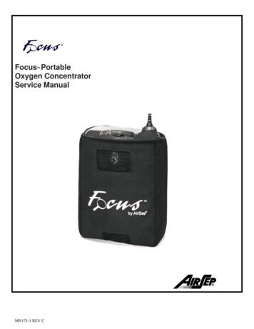
9Battery ReplacementLoosenscrews onbatterydoor in4 placesPositive ( ) end of batterytowards the top of the unit.The batteries are replaced by loosening the 4 thumbscrews on the battery door locatedon the front of the unit. The batteries should be removed by gently prying the top ( ) ofthe battery up and toward the bottom of the unit. Replace the batteries with 2 D sizealkaline batteries only. Do not mix new and old batteries when installing in unit. Thebatteries must be inserted with the positive ( ) end of the battery toward the top of theunit. For ease of installation, install the bottom (-) of the battery first. Replace thebattery door and tighten the 4 thumbscrews.Turn the unit on and verify that the displays turn on. Connect a 50 psi oxygen source tothe unit and verify that the unit does deliver breaths. The breath delivery alarm willsound if the unit is not connected to a test lung. This is normal and not a concern. Theventilator is now ready for use. Always turn the ventilator off when not in use topreserve battery life. The ventilator does not turn off automatically.Warning: Do not recharge alkaline batteries.10CleaningThe EPV200 should be cleaned after each use. To clean the EPV200, keep the gassupply hose on the unit to prevent contamination of the oxygen circuit.Warning: Cleaning procedures should be performed in an environmentfree of oil and petroleum based products.The EPV200 has been designed to be water resistant, but the unit cannot besubmerged or sprayed down for cleaning.Wipe the unit with a damp rag containing a mild detergent to remove any residue fromthe surface. Once the residue has been removed, the unit may be wiped with isopropylalcohol or a cold disinfecting solution to kill bacteria. The unit should then be wiped withwater to remove any film left by the cold disinfecting solution. Make sure the unit is drybefore putting the unit away.9
Following is a list of tested cleaning solutions:Isopropyl Alcohol: 70% IPAAlconox:1 tablespoon Alconox to 1 gallon H2OCetylcide:2 tablespoon Cetylcide to 1 gallon H2OBleach:10% bleach in H2ODispose of single patient use items per local biohazard standards.11Maintenance and ScheduleThe EPV200 should be checked annually to insure proper function. Batteries should bereplaced if they are beyond the expiration date on the battery. Replace with D sizealkaline batteries.Year 1:Perform Yearly Verification of function and Calibration procedure. Check batteryexpiration date; replace batteries as necessary.Year 2:Perform Yearly Verification of function and Calibration procedure. Check batteryexpiration date; replace batteries as necessary. Replace disposable O2 inlet hose with 6foot oxygen hose (see Accessories on page 14).Replace main valve with piston, o-ring, and spring for units manufactured before April2009. The manufacturing date is coded into the serial number for each unit. The firstfour digits identify the year of manufacture, and the next two digits identify the month ofmanufacture. Example: the serial number 20090403001 was manufactured in the year2009 and in the month of April. All repairs should be performed by Allied HealthcareProducts trained and certified technicians.Year 3:Perform Yearly Verification of function and Calibration procedure. Check batteryexpiration date; replace batteries as necessary.Year 4:Perform Yearly Verification of function and Calibration procedure. Check batteryexpiration date; replace batteries as necessary.Year 5:Perform Yearly Verification of function and Calibration procedure. Check batteryexpiration date; replace batteries as necessary.The unit has a life expectancy of 5 years based on normal usage and propermaintenance. A comprehensive rebuild will be necessary at this time, and should beperformed by Allied Healthcare Products trained and certified technicians.10
Yearly Verification of function and Calibration:Equipment Required Certified gas flow analyzer, capable of measuring BPM, inspiratory time andtidal volume Regulated 50 psi oxygen source New batteries 36 inches of 22 mm corrugated tubing or the allied patient circuit provided.Procedure Connect the 50 psi oxygen source to the oxygen inlet connector. Connect the 22 mm corrugated tubing to the patient circuit connection valve, andthe other end to the gas analyzer. Turn the tidal volume, inspiratory time and BPM to the values indicated in thetable below. Monitor the values to evaluate acceptability of the e Acceptable Setting Acceptable VolumeVolumeSettingValuesValueSetting Acceptable(seconds)(seconds)(ml)Value(ml)2.01.8 - 2.22018 -22400360 - 4402.01.8 - 2.2109 - 11800720 - 8802.01.8 - 2.2109 - 1112001080 -13201.00.9 – 1.13027 - 33200180 - 2201.00.9 – 1.12018 - 22400360 - 4401.00.9 – 1.12018 - 22600540 - 660 To test pressure relief, turn tidal volume to 640 ml, block the patient end of the22 mm corrugated tubing or patient circuit while monitoring the airwaypressure display. The airway pressure should not exceed 60 cm H2O. TheHigh Airway Pressure alarm should sound and a red LED should be activated.To test the breath delivery failure alarm, remove all obstructions from the patientcircuit connection valve and allow the ventilator to cycle. The breath deliveryalarm should sound, and a red LED should be flashing.To test the low source gas alarm, reduce the inlet pressure source to below35 psi. The low source gas alarm should sound and a red LED should beflashing.Should the unit fail any of these tests, contact the Allied Healthcare Products, Inc.,Technical Support Center in St. Louis: 314-771-2400 or 800-411-5136.11
12Check-out ProcedureThe unit should be checked for proper operation before each use. This can be doneafter cleaning to prepare the unit for the next use.Set the ventilator to the following settings: BPM 10 Tidal Volume 640 Inspiratory Time
the environments associated with emergency medical services (EMS), inter-hospital transport and hospital facility usage. This ventilator is intended to be used in temperatures of -9 to 50 C (15 to 122 F) and 5% - 95% relative humidity, non condensing. Biocompatibility testing has proven this ventilator to be safe for periods up to 14 days of