Transcription
Model: AHP300Electrically Controlled Ventilator1720 Sublette AveSt. Louis, MO 63110Phone 314-771-2400S168-AHP300-001Rev. DPatent Pending1
Table of Contents1.Intended Use: . 32.Product Description: . 43.Explanation of Warnings: . 44.Explanation of Abbreviations: . 55.Symbols: . 56.Controls and Connections: . 67.Operating the AHP300 Ventilator : . 88.Ventilation Modes: . 159.Breath Types: . 1810. Programmable Presets: . 19Quick Start Modes: . 19Custom Modes: . 2211. O2 Conserve Mode: . 2512. Manual Breaths: . 2613. Measured Parameters: . 2614. Alarms: . 2715. External Alarm Connection: . 3016. Battery Parameters: . 3117. AC Power Inlet and Auxiliary Power Connection: . 3218. Cleaning: . 3419. Check Out Procedure: . 3520. Pneumatic Diagram: . 3621.Maintenance:. 3722.Specifications:. 4323.Accessories and Replacement Parts: . 4724. NBR Filter: . 4825. Oxygen Cylinder Depletion Times: . 4926. Approximate Tidal Volume Settings based on Height: . 5027. Warranty: . 5128.Applicable Standards: . 52Models covered by this manual:AHP300 & AHP300-Y Transport Ventilator with Internal Air CompressorOther model available but not covered by this manual:AHP300P Transport Ventilator Basic Model (requires pneumatic gas source)CAUTION: Federal law restricts this device to sale by or on the order of a physician.Warning: The AHP300 Ventilator should not be used on children with aweight of 5 kg (11 lbs) or less.Warning: This device should only be operated by qualified personnelunder approved medical direction.Warning: Use only as directed. Improper usage or unauthorizedmodification of this product may result in user or patient injury or death.2
1. Intended Use:The AHP300 is intended to be used as an electrically controlled emergency ventilator thatcan use an external compressed gas source or its internal compressor. This ventilator isdesigned to provide emergency respiratory support by means of a face mask or tube insertedinto the patient’s airway. The ventilator is intended for use on patients weighing greater than5kg (11lbs). The ventilator is intended to be used in the environments associated withemergency medical services (EMS), inter-hospital transport and hospital facility usage byqualified, trained personnel under the direction of a physician. The ventilator is intended tobe used in temperatures of -18 C to 50 C (0 F to 122 F) and 5% to 95% RH non-condensing.Prior to use, first read and understand the instruction manual, charge the battery and thenfollow the check out procedure in Section 19.Each AHP300 ventilator includes the following:1 Ventilator1 Power Cord1 Oxygen Hose1 Instruction ManualWarning: Use only as directed. Always have an alternate means ofventilation available when using the ventilator in case of a mechanicalor system problem.This product has been designed and tested to have a 6 year product life.Caution: To ensure the ventilator performs reliably to specifications, the maintenanceschedule in section 21 must be followed.Latex Free: This product does not contain latex.Intended “users” of this device are: doctors, respiratory therapists, nurses and EMTs3
2. Product Description:The Transport Ventilator (AHP300) is an electrically controlled, portable emergencyventilator, which is designed to provide emergency respiratory support by means of a facemask or tube inserted into a patient’s airway. The AHP300 is capable of supporting thepatient’s respiratory efforts in a variety of modes. The modes are Volume assist control(Volume AC), Volume synchronized intermittent mandatory ventilation (Volume SIMV),Pressure control with assist control (Pressure AC), Pressure control with synchronizedintermittent mandatory ventilation (Pressure SIMV), and continuous positive airway pressure(CPAP). The AHP300 can deliver breaths to the patient using internal compressors as well asexternal gas sources.The AHP300 is intended for use on patients weighing greater than 5kg (11 lbs.). Thisventilator is intended to be used in the environments associated with emergency medicalservices (EMS), inter-hospital transport and hospital facility usage, by qualified, trainedpersonnel under the direction of a physician. The ventilator is intended to be used intemperatures of -18 C to 50 C (0 F to 122 F) and 5% to 95% RH non-condensing. TheAHP300 is intended to be used on one patient at a time. The unit can be reused after it hasbeen cleaned and the single use patient circuit has been replaced.Biocompatibility testing has proven this unit safe for periods up to 24 days of continuous use.Results beyond this time are not known.Warning: The AHP300 is not MRI compatible.Caution:Federal law restricts this device to sale by or on the order of aphysician.Caution:The AHP300 should not be used on children with a weight of5kg (11 lbs) or less.3. Explanation of Warnings:Warning:Caution:Potential injury to the patient or operator exists.Potential damage to the ventilator, breathing circuit or otherequipment may result.Warnings and cautions should be read and understood before operating the ventilator.4
4. Explanation of Abbreviations:VtBPMfTiPsicm H2OkpamlLPMmmLEDCPRLPAHPARHDelivered Tidal VolumeBreaths per Minute (Respiratory Frequency)Frequency (Respiratory Rate)Inspiratory TimePounds per Square InchCentimeters of WaterKilopascalMillilitersLiters per minuteMillimetersLight emitting diodeCardio Pulmonary ResuscitationLow pressure alarmHigh pressure alarmRelative Humidity5. Symbols:Degree of protection against electric shock: Type BFCaution, Consult accompanying documents% Relative Humidity: 5 to 95%Non-CondensingTemperature Range:-18 C to 50 C (0 F to 122 F) Operating-40 C to 60 C (-40 F to 140 F) Storage Off OnExternal AlarmDo not Occlude5
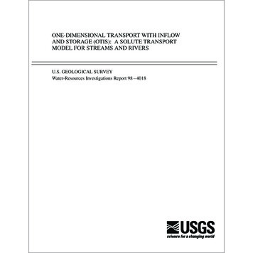
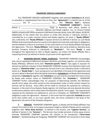
6. Controls and ontrol PanelItem #Description1Power On/Off2Quick Start Adult Button3Quick Start Child Button4Tidal Volume Setting5O2 % Setting6I time Setting7BPM Setting8PEEP / CPAP Setting9Peak Inspiratory Pressure10Pressure Support Setting11Breath Trigger Sensitivity12High Airway Pressure Alarm SettingItem #1314151617181920212223242561917DescriptionLow Airway Pressure Alarm SettingVentilation Mode SelectionCustom Mode SelectionParameter Adjustment ButtonsControl Lock ButtonManual Breath ButtonExternal Power IndicatorsBattery Status IndicatorO2 Conserve ModeAlarms / Silence Reset ButtonMeasured ParametersFlow Setting (Volume Modes)I:E Ratio (Based On Vent Settings)
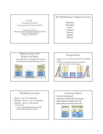
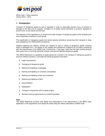
Ventilator Connections:96872134Item #12345510DescriptionAC PowerExternal BatteryO2 Source (Fresh Gas)Air Source (Fresh Gas)Low Pressure O2 Source(Fresh Gas)Item #6789107DescriptionRemote Alarm ConnectionPatient Circuit Connection PortPatient Airway Pressure (blue)Exhalation Valve ControlAir Intake Port
7. Operating the AHP300 Ventilator :The following steps will guide a person through the setup and operation of the AHP300ventilator. Connecting to an Oxygen Source:Located on the left side of the AHP300 are 2 diameter index safety system (DISS) fittings,one for Oxygen and one for Medical Air. Connect the appropriate 50 psi gas source with aminimum of 80 LPM flow capacity to these fittings. The AHP300 may be used without anexternal gas source. The AHP300 has an internal compressor that can be used to supplyambient air to the patient.Warning: Proper tidal volumes may not be provided with a gas sourcenot providing a minimum of 80 LPM at 280 kPa (40 psi).Warning: This device operates with medical gases under pressure,including oxygen. Do not use this device while smoking or near openflames. Do not use this device or operate near flammable materials.Warning: Do not use on this device in the presence of flammableanesthetics.Warning: Verify that there are no noticeable leaks after connection tothe 344 kPa (50 PSI) Medical O2 or Medical Air source.Caution: In order to provide optimal performance, check all gassupplies to assure only medical grade gas is used.8
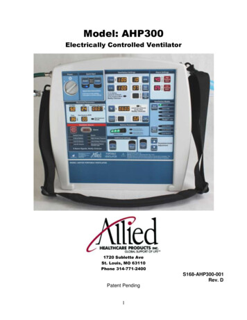
Connecting the patient breathing circuit:Located on the right side of the unit is a 22mm patient connection port for a patient breathingcircuit. Install the corrugated tubing over the connector so that it is on securely. The tubingwill not pull off easily when properly installed. Connect the small tube without a connector tothe small barb labeled Exhalation Valve. Connect the tube with a connector to the blue barblabeled Patient Airway.Warning: Do not use unapproved patient circuits as loss ofperformance may result.Ventilator Patient CircuitThe AHP300 uses a universal single limb ventilator patient circuit (pictured below).Allied Healthcare Products Adult CircuitPart number L599-600Dead space 64.1 ml*Exhalation resistance 6 cmH2O (Approximately 4 at 60 LPM)(Approximately 3 at 30 LPM)Allied Healthcare Products Pediatric CircuitPart number L599-650Dead space 9.2 ml*Exhalation resistance 6 cmH2O (Approximately 4 at 60 LPM)(Approximately 3 at 30 LPM)9
*Too large of an apparatus dead space can affect the oxygen and other gas levels deliveredto the patient. The addition of accessories may impact the dead space and must beconsidered when they are used. Addition of accessories may impact the exhalation resistance.Do not use circuits with “anti-static” or electrically conductive tubing or hoses.Warning: Ventilator patient circuits may become contaminated during use. Toprevent cross contamination do not reuse patient circuits without properdisinfecting. Never reuse a “single patient use” ventilation circuit.Always verify the ventilator circuit is not leaking by checking the connections to ensure theyare pushed on completely. Verify the exhalation valve is on tight and not leaking duringbreath delivery.Installation of a mask to the patient circuit is done by pushing the mask onto the end of the90degree elbow at the patient end of the circuit as shown below.Another option is use an exhalation filter to limit the spread of bacteria. L599-200 exhalationfilters may be used as shown below.Additional exhalation resistance will be experience when using an exhalation filter. Theresistance based on flows is listed below.Flow Condition Exhalation Resistance(Lpm)(cm H2O)151.45303.15455.07607.308010.6110
Turn the ventilator “ON” by rotating the knob in the “Power” section of the control panel to the“ ” position. Select the Desired Ventilation Mode:If the control lock is activated as shown below it must be deactivated before any adjustmentscan be made. This is done by pushing the control lock button and the light will turn off tosignify control lock is no longer active. Pushing the control lock button when the control lockis not active will activate the control lock as indicated by the light above the button.Push the Mode Selection button and the current mode (for example Volume AC) will begin toflash. Using the Parameter/Mode adjustment buttons you can move the flashing light to themode you desire. Push the mode selection button a second time and that mode will becomethe active mode of ventilation. If you do not push the mode selection button a second timeafter selecting a mode the ventilator mode change will time out in 5 seconds and exit themode selection process. The ventilator will stay in the current mode of operation.11
Select the Required Parameters:‘The ventilator will automatically populate the required fields with the current values.The table below shows the parameters that must be set in each mode.Ti (Inspiratory Time)BPM (Frequency)%O2PEEP/CPAPPIPVt (Tidal Volume)Pressure SupportTrigger SensitivityHigh Pressure AlarmLow Pressure AlarmO2 ConserveVolume OptionalRequiredRequiredRequiredOptionalPressure iredOptionalWarning: A CBRN Filter is required when the ventilator compressor isused in an environment where the air is not safe to breath.You can then change the ventilation parameters by pushing the button next to the parameteryou want to change and then use the parameter/mode adjustment buttons to change thevalue.12
For example the inspiratory time can be adjusted by pushing the button labeled “I. Time”.When you push the button the display will begin to flash, the value will change each time oneof the parameter adjustment buttons is pushed. The inspiratory time may be adjusted from .5to 2.0 seconds. If the ventilator is in a volume mode and the new inspiratory time is too shortor long for to achieve the set tidal volume the light next to the tidal volume setting will comeon and the inspiratory time will not be changed to a setting that does not allow the currenttidal volume setting. The tidal volume must be changed if that inspiratory time is desired.The following table lists the tidal volumes and BPMs that may be used based on the setinspiratory time.Inspiratory Time.5.751.01.251.51.752.0Tidal Volume Range40 to 500 ml60 to 750 ml80 to 1000 ml100 to 1250 ml125 to 1500 ml150 to 1750 ml175 to 2000 mlBPM Range0 and 5 to 600 and 5 to 450 and 5 to 300 and 5 to 200 and 5 to 200 and 5 to 200 and 5 to 20The AHP300 has a flow range from 5 to 60 LPM in volume control mode.In pressure control mode a Peak Inspiratory pressure (PIP) from 15 to 55 cm H 2O is set. Inthis mode the peak flow may be greater than 80 LPM and the flow will vary during the breath.The flow rate will be higher in the beginning of the breath and lower as the airway pressureapproaches the peak inspiratory setting. See section 8 for more detail on breath types.As the BPM or Inspiratory time is adjusted the I:E ratio will be updated on the ventilatordisplay. This is the calculated ratio of the inspiratory time to the expiratory time. The numberdisplayed indicates how much longer or shorter the expiratory time is compared to theinspiratory time. For example if a 2 is displayed it means the expiratory time is 2 times aslong as the inspiratory time. See section 14 for more detail.The % O2 indicates the percentage of oxygen in the gas delivered to the patient. Forexample, “100” indicates that the delivered gas is all oxygen, while “21” indicates that it is allair. This value is adjustable from 21 to 100 with an accuracy of 12% of the setting. Forexample a %O2 setting of 50 would have a tolerance of 6 giving a potential range of 44 to56%. If you select a value that cannot be achieved due to a gas supply not being connectedor having low pressure, a gas source alarm will sound. If only oxygen is connected, theAHP300 will use the internal compressor to supply air and there will not be an alarm. If youselect a %O2 of 70 when only oxygen is available, the ventilator will activate the internalcompressor to provide the required air flow so that the set tidal volumes can be delivered.PEEP may be used in any volume or pressure mode. PEEP (positive end expiratorypressure) will hold a set pressure at the end of exhalation portion of a breath. This pressurekeeps the lungs partially inflated to help the exchange of oxygen through the alveoli. ThePEEP setting may be set from 0 to 25 cm H2O.13
The PEEP/CPAP setting also controls the pressure level for CPAP (Continuous PositiveAirway Pressure). See section 9 for more detail.Safety Pressure Relief:This ventilator has a mechanical pressure relief set at 85 cm H2O (maximum limitedpressure). When the airway pressure reaches this limit the valve will open and gas will bevented to prevent the pressure from continuing to build. This is a redundant safety device asthe high airway alarm limits the maximum pressure.Warning: Preset tidal volumes may not be delivered when the pressurerelief setting is reached. Inspiratory times will remain constant,however no additional tidal volume will be delivered after the pressurerelief limit is reached. Connect the patient breathing circuit to the patient:The patient breathing circuit has been designed to fit with an oxygen mask (22mm outsidediameter) or endotracheal tube (15mm inside diameter). Follow the established guidelinesfor maintaining the patient’s airway. Verify the patient is receiving good ventilation:Once the patient is connected to the ventilator the patient should be observed to make surethey have adequate chest rise and fall. The chest rise should be even and should return to anormal position. If the patient does not have adequate chest rise check the tidal volume orpressure control setting, patient connections and examine the patient for a possibleobstruction of the airway or other injury. The patient should be monitored to make sure theya
emergency medical services (EMS), inter-hospital transport and hospital facility usage by qualified, trained personnel under the direction of a physician. The ventilator is intended to be used in temperatures of -18 C to 50 C (0 F to 122 F) and 5% to 95% RH non-condensing.