Transcription
Installation and Setup GuideEMC Data Domain DD2500 System Installationand Setup Guide302-001-374REV. 02February, 2015This document provides installation for the rack bracket and the DD2500 system and initialconfiguration instructions.llllllllllllllRelated documentation.2Tools and supplies needed. 3Safety information. 3Description of the system.4Unpack the system. 12Install the rack brackets. 12Install the system in the rack.16Install the cable management arm (CMA). 17Install the bezel. 19Connect data cables. 19Powering on the controller. 19Enable administrative communication. 20End User License Agreement (EULA) . 20Run the configuration wizard.21
Installation and Setup GuideRelated documentationEMC provides a variety of document types to support our products. End-user documentsinclude user guides, hardware installation guides, administrator guides, software guides,part replacement guides, release notes, and others. Integration documents describe howto integrate Data Domain systems with third party backup applications, and compatibilitymatrices show which components are compatible with each other.This document refers to other EMC documents by title. To locate a referenced document,go to the EMC Support website at https://support.emc.com, enter the document title inthe search box, and click the search button.NoteHard copies of a document may be out of date. Always check for the current version of adocument before you start an upgrade or begin a significant configuration change.Viewing Data Domain documentsProcedure1. Log into the EMC Online support site at: https://support.emc.com.2. To view user documents, click Product Documentation and then perform the followingsteps:a. Select the Data Domain model from the Platform list and click View.b. On the row for the correct Data Domain operating system (DD OS) version, clickView under Documentation.c. Click the desired title.3. To view integration-related documents, perform the following steps:a. Click Integration Documentation.b. Select the vendor from the Vendor dropdown list.c. Select the desired title from the list.4. To view compatibility matrices, perform the following steps:a. Click Compatibility Matrices.b. Select the desired title from the Current Releases list.Where to go for more information2For information about:Go to https://support.emc.com/How to configure the systemEMC Data Domain Operating System InitialConfiguration GuideNew features, enhancements, known issues,and late-breaking news about your DataDomain software releaseEMC Data Domain Operating System ReleaseNotes for your software releaseHow to manage the Data Domain operatingsystemEMC Data Domain Operating SystemAdministration Guide for your software releaseInstallation and Setup Guide
EMC Data Domain DD2500 System Installation and Setup GuideFor information about:Go to https://support.emc.com/How to install and use the DD Boost softwareand plug-inEMC Data Domain Boost for OpenStorageAdministration Guide for your software releaseHow to replace Data Domain hardwarecomponentsSpecific part installation guidesHow to use third-party applicationsIntegration documentation and compatibilitymatricesTools and supplies neededFor a list of recommended tools and supplies for field work, see the document titled FEToolkit Inventory and Common Procedures for FRU Tasks at https://support.emc.com.Safety informationCAUTIONlIf the system is used in a manner not specified by the manufacturer, the protectionprovided by the equipment may be impaired.lThe RJ-45 sockets on the motherboard, PCI cards, or I/O modules are for Ethernetconnection only and must not be connected to a telecommunications network.Review this list of important safety recommendations.lAll plug-in modules and blank plates are part of the fire enclosure and must beremoved only when a replacement can be added immediately. The system must notbe run without all parts in place.lA controller must be operated only from a power supply input voltage range of 100–240 VAC, 50–60 Hz.lEach component is intended to operate with all working power supplies installed.lProvide a suitable power source with electrical overload protection.lA safe electrical earth connection must be provided to each power cord. Check thegrounding of the power sources before applying power.lThe plug on each power supply cord is used as the main disconnect device. Ensurethat the socket outlets are located near the equipment and are easily accessible.lPermanently unplug the unit if you think it is damaged in any way and before movingit. If the unit is powered by multiple sources, disconnect all supplied power forcomplete isolation.lThe power connections must always be disconnected prior to removal or replacementof a power supply module from any of the components in the system.lA faulty or failed fan module should be replaced as soon as possible. A faulty orfailed power supply module must be replaced within 24 hours.lEMC Data Domain systems are heavy. Use two people or a mechanical lift to moveany system.lTo comply with applicable safety, emission, and thermal requirements, covers mustnot be removed and all bays must be fitted with plug-in modules.Tools and supplies needed3
Installation and Setup GuidelLoad the rack beginning at the bottom to prevent the rack from becoming top-heavy.lFor ESD protection, EMC Data Domain recommends that you wear a suitable antistaticwrist or ankle strap. Observe all conventional ESD precautions when handling plug-inmodules and components.lDo not extend components on slide rails until you have loaded at least three or moresimilarly weighted items in the rack, or unless the rack is bolted to the floor oroverhead structure to prevent tipping.Description of the systemThis section includes site requirements, product specifications, and descriptions of frontand rear panels.Site requirementsThe site requirements are:lThe system requires 2U of vertical space in a standard 19”, four-post rack. Do not usea two-post rack.lUse air conditioning that can cope with the maximum BTU/hour thermal rating.lTemperature control required with a gradient (change) not to exceed 30 C in an hour.lIn a closed or multi-unit rack, ensure that the unit has adequate airflow through thefront bezel and back panel and that ambient temperature requirements are met.lEnsure that the front bezel and back panel clearances are met.lEnsure that cables at rear of unit do not obstruct exhaust airflow.lIf installing in a closed cabinet, ensure that the front and rear doors have at least65% open area to ensure adequate airflow for cooling.lFront bezel requires 1.56 inches (4.0 cm) of unobstructed clearance.lBack panel requires 5 inches (12.7 cm) of unobstructed clearance.lAC power outlets must be provided with an earth ground conductor (safety ground). Asafe electrical earth connection must be provided to each power cord.lRequired voltage: 100-120 V or 200-240 V . Frequency: 50 to 60 Hz.System specificationsModelWattsBTU/ Power (VA)hour (120V/230V)Size (U)PowerconnectorsWeightWidthDepthHeightDD2500with 7drives3941345406 (3.38A/1.76A)22 x grounded,120 VAC, NEMA15P/R65 lb. /29.5 kg.19 in. /48.3 cm.29.5 in. /74.9 cm3.5 in. /8.9 cm.DD2500with 12drives4871662502 (4.18A/2.18A)22 x grounded,120 VAC, NEMA15P/R73 lb. /33.1 kg.19 in. /48.3 cm.29.5 in. /74.9 cm.3.5 in. /8.9 cm.4lOperating temperature: 50 to 95 F (10 to 35 C), derate 1.1 C per 1000 feet,above 7500 feet up to 10,000 feet.lOperating humidity: 20% to 80%, non-condensing.Installation and Setup Guide
EMC Data Domain DD2500 System Installation and Setup GuidelNon-operating temperature: -40 to 149 F (-40 to 65 C).lOperating acoustic noise: Sound power, LWAd, is 7.52 bels. Sound pressure, LpAm,is 56.4 dB. (Declared noise emission per ISO 9296.)Storage capacityThe table lists the capacities of the DD2500 system. Data Domain system internalindexes and other product components use variable amounts of storage, depending onthe type of data and the sizes of files. If you send different data sets to otherwiseidentical systems, one system may, over time, have room for more or less actual backupdata than another.NoteData Domain system commands compute and display amounts of disk space or data asdecimal multiples of certain powers of two (210, 220, 230, and so forth). For example, 7GiB of disk space 7 x 230 bytes 7 x 1,073,741,824 bytes. EMC Data Domain refers tothis process as Base 2 calculation.Table 1 DD2500 storage age(Base10)Data StorageSpace(Base 2Calculation)Data Storage External StorageSpace(Base 10Calculation)DD25004 x 8 GBDIMMSeven ortwelve 3.5in. 3 TBSAS HDDs21 TB or36 TB7 drives: 10671GiB7 5 drives:18763 GiB7 drives:11458 GiB7 5 drives:20147 GiB11 x 30-TB SAS shelf;up to 30 TB of rawcapacity.12 drives: 24334 12 drives:GiB26129 GiBDD25008 x 8 GBDIMMSeven ortwelve 3.5in. 3 TBSAS HDDs21 TB or36 TB7 drives: 10671GiB7 5 drives:18763 GiB7 drives:11458 GiB7 5 drives:20147 GiB12 drives: 24334 12 drives:GiB26129 GiBUp to a maximum of 4x 30-TB SAS shelvesor 3 x 45-TB SASshelves; up to 135 TBof raw capacity.NoteFor information about Data Domain expansion shelves, see the separate document, EMCData Domain Expansion Shelf Hardware Guide.Storage capacity5
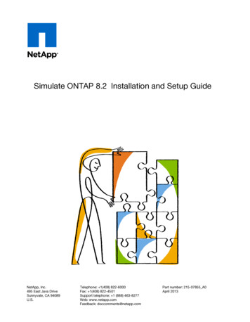
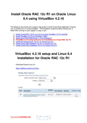
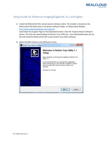
Installation and Setup GuideFront panelFigure 1 Front panel componentsFront LED indicatorsThe front of the system contains 12 disk drive status LEDs that are normally blue andblink when there is activity on the disk. The LEDs are shaped like triangles, and the apexof the triangle points either left or right toward the disk whose status it represents. If thedisk drive has a failure, the disk’s status LED turns from blue to amber.There are two square-shaped system LEDs. A blue system power LED is on whenever thesystem has power. An amber system fault LED is normally off and is lit amber wheneverthe chassis or any other FRU in the system requires service.Figure 2 Disk and system LEDs1. System fault LED (square shaped).2. System power LED (square shaped).3. Disk drive LEDs (triangular shaped).PartStateSystem faultNormally unlit. Amber indicates fault.System powerSteady blue indicates normal power.Disk drive statusSteady blue or blinking blue indicates normal operation. Amberindicates fault or failure.When the bezel is affixed, the blue system power LED can be seen through the bezel.6Installation and Setup Guide
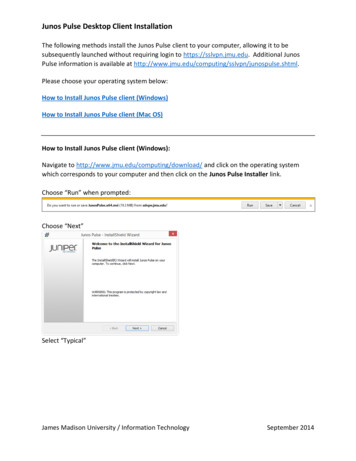
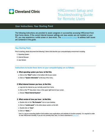
EMC Data Domain DD2500 System Installation and Setup GuideFigure 3 Bezel showing lighted system power LEDDisk drivesThe system contains up to 12 hot-swappable 3.5" HDD SAS disk drives, located in thefront of the chassis. Left to right, drives are numbered 0-3 in the top row, 4-7 in themiddle row, and 8-11 in the bottom row.lThe base configuration contains 7 disk drives in locations 0 through 6. Drive bays7-11 contain bay blanks.lThe expanded configuration contains 12 disk drives.Back panelFigure 4 Features on rear of chassis1. Slot 0.2. Slot 1.3. Slot 2.4. Slot 3.5. Slot 4, NVRAM-BBU combination module.6. Onboard interfaces.7. Power supply, number 0.8. Power supply, number 1.Back panel7
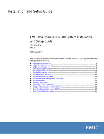
Installation and Setup GuidePort layoutFigure 5 Port numbers on back panel1. Physical 4, logical ethMe (10GBaseT).2. Physical 2, logical ethMc (1 GE).3. Physical 0, logical ethMa (1 GE).4. Service network port.5. Physical 5, logical ethMf (10GBaseT).6. Physical 3, logical ethMd (1 GE).7. Physical 1, logical ethMb (1 GE).8. USB port.9. Serial port (DB-9, RS-232).Power supply unitsA system has two power supply units, numbered 0 and 1 from left to right. Each powerunit has LEDs (shown in the photo) that indicates the following states:lAC LED (top): Glows green when AC input is good.lDC LED (middle): Glows green when DC output is good.lSymbol “!” (lower): Glows solid amber for fault or attention.Figure 6 Power supply unit LEDs8Installation and Setup Guide
EMC Data Domain DD2500 System Installation and Setup GuideOnboard interfaces and LEDsFigure 7 Onboard interfaces and LEDs1. Serial number label.2. SP power LED (top); SP service LED (bottom).3. Dual-port 10GBaseT.4. Quad-port Gigabit Ethernet.5. Service network port (top); USB port (bottom).6. Serial port.The onboard interfaces and LEDs are located at the far lower left side of the back of thesystem. The onboard interfaces enable you to check system status and connect to thesystem through a serial console or Ethernet connections. The dual-port 10GBaseT andquad-port Gigabit Ethernet interfaces allow connectivity to the data host.A USB port enables the system to boot from a USB flash device.Rear LED status summaryPartStateSP serviceBlue indicates normal operation. Amber indicates fault.SP powerSteady green indicates normal power. Dark indicates no power.I/O moduleSteady green indicates normal operation. Amber indicates fault orfailure.Power supply ACGlows green when AC input is operational.Power supply DCGlows green when DC output is operational.Power supply symbol “!”Glows solid amber for fault or attention.Onboard interfaces and LEDs9
Installation and Setup GuideI/O modules and slot assignmentsSee DD2500 slot assignments on page 10 for the I/O module slot assignments of thesystem.Table 2 DD2500 slot assignmentsSlot NumberDD2500 System0FC, Ethernet or empty1FC, Ethernet or empty2FC, Ethernet or empty3SAS or empty4NVRAM-BBUWhen a DD2500 system is upgraded, the newly inserted I/O module should go into thenext available slot position. The following slot loading rules apply:lFor mixed populations, populate all Ethernet I/O modules first, then populate the FCI/O modules.lFor Ethernet I/O modules, populate the leftmost (slot 0) slot first, if empty, then slot 1and so on.lSlot 3 is reserved for SAS I/O modules only.FC I/O module optionThe FC I/O module is a dual-port Fibre Channel module. The optional virtual tape library(VTL) feature requires at least one FC I/O module. Three FC I/O module slots are availablefor use.Ethernet I/O module optionsThe following Ethernet I/O modules are available:lDual Port 10GBase-SR Optical with LC connectorslDual Port 10GBase-CX1 Direct Attach Copper with SPF modulelQuad Port 1000Base-T Copper with RJ-45 connectorslQuad port 2-port 1000Base-T Copper (RJ-45)/2-port 1000Base-SR OpticalYou can use up to three I/O module slots for Ethernet connectivity.Internal system componentsThe photo shows the system with the storage processor (SP) module removed from thechassis. The top of the photo shows the rear of the system.10Installation and Setup Guide
EMC Data Domain DD2500 System Installation and Setup GuideFigure 8 Top view of SP module (DD2500 system shown)Cooling fansA system processor module contains seven cooling fans. The fans provide cooling for theprocessor, DIMMs, and I/O modules. A system can run with one fan module faulted.Figure 9 Top view of SP module with air ducts removedDIMM modulesDD2500 systems can contain either 4 x 8 GB or 8 x 8 GB memory DIMMs.Internal system components11
Installation and Setup GuideUnpack the system1. Open the “Open Me First” box.2. Remove the accessories and rack-mount kit from the shipping packages.3. Remove the controller and bezel from the shipping packages.Install the rack bracketsData Domain systems are installed into racks using the rack bracket hardware.Bracket hardwareThe rack-mounting kit is compatible with racks that have front-to-rear post spacingbetween 18 inches and 36 inches. The kit will fit the following types of mounting holes:l7.1 mm round holesl.375 inch / 9.2 mm square holeslM5, M6, 12-24, and 10-32 threaded holesThe kit includes the following items:lTwo bracket assemblies, one marked for the left (L) side and one marked for the right(R) side of the rack.Figure 10 Bracket assembly1. Front.2. Back.12Installation and Setup Guide
EMC Data Domain DD2500 System Installation and Setup GuideFigure 11 Bracket assembly adapter screws and orientation marking1. Adapter screws.2. “L” for left side.lGap filler (2)Figure 12 Gap fillerlAssorted screws.lOne multipurpose screwdriver.Install the brackets onto the rackBefore you beginNotelDo not hold the bracket assembly in a vertical position as the parts may separate.lThe Data Domain system is two rack units (RU) tall. Make sure the location in the rackfits the product.Procedure1. If your rack contains round unthreaded or square holes, skip to the next step. If yourrack contains threaded holes, unscrew and remove the screw caps at both ends ofeach bracket.Install the brackets onto the rack13
Installation and Setup GuideFigure 13 Rear screw caps (for threaded hole racks)NoteThe rear guide pin is shown between the two screw caps.1. Bracket screw caps.Figure 14 Remove front screw caps2. As needed, select the bracket marked right or left. Orientation assumes you are facingthe front of the rack. The rear of the bracket contains an adjustable piece.14Installation and Setup Guide
EMC Data Domain DD2500 System Installation and Setup GuideFigure 15 Rack bracket1. Front.2. Back.3. From the rear of the system, hold the bracket against the inside of the rack posts.Align the rear guide pin and slide the bracket towards the front.CAUTIONIf the bracket is mounted in holes that are not vertically aligned from front to back,the bracket may be damaged and mounting will not be secure.4. Pull the adjustable sliding part of the bracket towards the front until it is close to, butnot touching, the front of the rack. The bracket adjusts to fit most racks.5. Attach the bracket to the rear of the rack using the furnished screws. There are sixholes. Add screws to the second and fifth holes.NoteIf more convenient, you may attach the second bracket while still at the rear of therack.6. If your rack contains threaded holes, add a gap filler to the front end of the bracket atthe front of the system. Otherwise, skip to the next step.7. Attach the bracket (along with the gap filler, if applicable) to the front of the rack.There are five holes in the front. Add a screw to the fourth hole. See the photo.Install the brackets onto the rack15
Installation and Setup GuideFigure 16 Attach bracket to front of rack1. Hole for top register pin on the system.2. Hole for captive screw on the system.3. Add a second, optional screw to secure the system.4. Attach the rail to the rack using a provided screw.5. Hole for bottom register pin on the system.NoteThe optional screw is used to secure the system to the rack if it is necessary to movethe rack.8. Verify that the bracket is level.9. Repeat the steps to attach the remaining bracket to the other side of the rack.10.After installing both brackets, make sure that they are level with one another.Install the system in the rackCAUTIONThis procedure requires two people or a mechanical lift.Procedure1. With the system in the front of the rack, orient the syste
Viewing Data Domain documents Procedure 1. Log into the EMC Online support site at: https://support.emc.com. 2. To view user documents, click Product Documentation and then perform the following steps: a. Select the Data Domain model from the Platform list and click View. b. On the row for the correct Data Domain operating system (DD OS .