Transcription
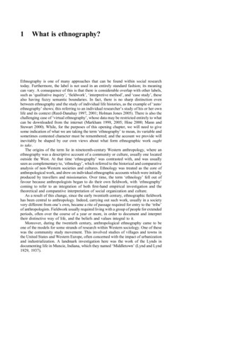
A surface electrode point Paul trapTony Hyun Kim,1, Peter F. Herskind,1 Taehyun Kim,2 Jungsang Kim,2 and Isaac L. Chuang11Center for Ultracold Atoms, Department of Physics, Massachusetts Institute of Technology77 Massachusetts Avenue, Cambridge, MA 021392Department of Electrical and Computer Engineering, Duke University Durham, NC 27708(Dated: September 16, 2010)We present a model as well as experimental results for a surface electrode radio-frequency Paultrap that has a circular electrode geometry well-suited for trapping of single ions and two-dimensionalplanar ion crystals. The trap design is compatible with microfabrication and offers a simple methodby which the height of the trapped ions above the surface may be changed in situ. We demonstratetrapping of single 88 Sr ions over an ion height range of 200–1000µm for several hours under Dopplerlaser cooling, and use these to characterize the trap, finding good agreement with our model.I.INTRODUCTIONRadiofrequency (rf) traps have been applied extensively in a large variety of scientific studies over the pastsix decades. Originating from mass spectrometry [1],they have then been applied in fields such as metrology [2], quantum information science [3, 4] and coldmolecular physics [5, 6], to mention but a few.Traditionally, such devices have been rather bulky,three-dimensional structures that required precise machining and careful assembly. Recently, however, thefour-rod linear Paul trap (see Fig. 1a) has been transformed into a two-dimensional structure, with all electrodes in a single plane above which ions can betrapped [7]. This new class of so-called surface trapsoffer a tremendous advantage over their predecessors inthat electrodes can be defined lithographically with extremely high precision and that construction can leveragethe techniques of microfabrication, with the possibilityof incorporating the technology of CMOS for integratedcontrol hardware [8, 9]. These aspects are particularlyattractive to applications in quantum information processing where limitations are currently, by a large degree,pertaining to the scalability of devices for trapping as wellas certain elements of infrastructure such as optics, laser(a)GNDRF(b)RFRFGNDGNDGNDFIG. 1. Comparison of the traditional four-rod linear Paultrap (a) to the point Paul trap (b). The latter achievesquadrupole ion confinement through rf on a single, ringshaped electrode. Dashed lines suggest how cylindrical elements – such as optical fibers – may be introduced to thepoint Paul geometry. kimt@mit.edulight delivery, and control electronics.In this paper we study a novel type of rf surface trapwith a high degree of symmetry in its electrode geometry.The generic geometry of this trap, which we shall referto as the point Paul trap, is shown in Fig. 1b, and mayconsist of any number of concentric electrodes of arbitrary widths to which different voltages can be applied.This design originated in a study of surface electrodetraps [10, 11], but was subsequently strongly inspired bywork on planar Penning traps [12], where a similar geometry was used to create a static electric quadrupole fieldthat, when combined with a strong homogeneous magnetic field, gave rise to a confining potential above thesurface of the electrodes. The point Paul trap also bearsclose resemblance to the rf ring- and the rf hole-traps [13];however differs in that the ion is trapped above the surface of the electrodes as opposed to in-between, whichmakes this geometry better suited for microfabrication.A consequence of the azimuthal symmetry of theelectrodes is that the rf-field exhibits a nodal pointrather that a nodal line as in the linear Paul trapand that the confining fields originate exclusively fromthe rf-potential, rendering the addition of dc-potentialsnonessential for anything but the compensation of straycharges on the trap. This makes the point Paul trapwell-suited for confinement of single ions, which may thenreside at the rf-nodal point where the amplitude of therapidly oscillating rf-field vanishes.The ability to fabricate these traps in a scalable fashion makes them attractive for realizing large arrays ofsingle ions in independent traps that may be utilized fora quantum processor, provided the individual ions can beinterconnected, e.g., through optical fibers [14–16]. Onthis aspect, the axial symmetry of the trap lends itselfwell to integration of such fibers and potentially otheroptical elements that also possess axial symmetry. Thefiber, for instance, may be introduced through the electrodes directly beneath the ions with minimal perturbation of the trapping fields.Another possible application of this trap is in thefield of quantum simulation. While classical computersare unable to efficiently simulate coupled spin systems,such simulations may be implemented using a quan-
2tum mechanical system of effective spins, such as a twodimensional lattice of interacting ions. The resulting potential of the point Paul trap provides ion crystals withexactly the requisite two-dimensional planar structure.As such, the system could be used to simulate e.g. afrustrated spin system [17, 18], as was demonstrated recently [19].We also find that our trap design is ideally suited forrealizing a scheme by which the height of a single trappedion above the trap surface is varied in-situ. This capability may prove extremely useful in the search for theorigin of anomalous heating in ion traps – a problemcurrently impeding the advancement of quantum computation with trapped ions [20, 21]. It also provides ageneral technique by which oven contamination of thetrap can be minimized by loading further away from thetrap surface, and subsequently bringing the ion to thedesired trap height.This paper is organized as follows: in Section II wepresent a model for the planar point Paul trap, deriveanalytic expressions for the relevant trapping parameters, present full numerical results of trap optimization,and consider a scheme for the variation of the ion heightabove the trap surface. In Section III we describe our experimental setup used for the verification of the model;and in Section IV we present experimental results fortrapping of single and few ions in a printed circuit board(PCB) implementation of the point Paul trap.II.POINT PAUL TRAP MODELWe proceed with a general treatment applicable to anarbitrary number of circular electrodes, and then focuson a particular geometry that we will study experimentally later in Sections III and IV. Further theoreticaldiscussion can be found in [22, 23]. At the end of thissection we also describe a scheme for variation of the ionheight above the trap surface.A.Potential from annular planar electrodesWe begin with the general solution to the Laplaceequation in charge-free space and express this in cylindrical coordinates for z 0, yielding [24] Z XJm (kρ)e kz(1)Φ(z, ρ, φ) m 0zzV1 V2 V3 . VnρφyxFIG. 2. The generic layout of the point Paul trap, which consists of concentric annular electrodes with arbitrary widths,illustrated in a cylindrical coordinate system.In turn, A0 can be expressed as A0 (k) whereAi (k) kZPniAi (k),βiρJ0 (kρ)Vi (ρ)dρ.(3)αiAll information about the electrode geometry is now included in the A0 coefficient, which we have in turn written as a sum of n sub-coefficients, each accounting for theeffect of a single annular electrode i with inner radius αi ,outer radius βi and a voltage Vi , which we shall assume isconstant across the electrode. The integral of Eq. (3) canbeR u evaluated using the identity for the Bessel functionsvJ0 (v)dv uJ1 (u) to give0Ai (k) Vi [βi J1 (kβi ) αi J1 (kαi )] .(4)This completes the general treatment of the problem:The electric potential above a surface at z 0 withn concentric circular electrodes, each with independentvoltages Vi and inner and outer radii of αPi nand βi respectively, is given by Eq. (2) with A0 (k) i Ai (k), wherethe Ai coefficients are given by Eq. (4).B.The three-electrode point Paul trap0 [Am (k) cos (mφ) Bm (k) sin (mφ)] dk.where Jm (kρ) are the usual Bessel functions and Am (k)and Bm (k) are coefficients to be determined based onthe boundary conditions of the problem. Based on theazimuthal symmetry of Fig. 2, Eq. (1) further simplifiesto [24]Z J0 (kρ)e kz A0 (k)dk.(2)Φ(z, ρ) 0While static potentials alone may provide confinementin one or two dimensions, Earnshaw’s theorem dictatesthat this is accompanied by a defocusing effect in theorthogonal dimensions. In the work of Ref. [12], threedimensional confinement was achieved via the addition ofa static magnetic field to realize a planar Penning trap.Here, we use a time-varying rf field to achieve chargeconfinement as a planar Paul trap. Namely, we considerthe simple geometry of only three electrodes defined by
3the following boundary conditions: for 0 ρ a, 0Φ(z 0, ρ) Vrf cos (Ωrf t) for a ρ b, 0for b ρ ,(5)where Vrf is the amplitude of the applied voltage and Ωrfis the frequency. The resulting potential then readsΦ(z, ρ, t) Vrf cos (Ωrf t)κ(z, ρ),(6)whereκ(z, ρ) Z0 [bJ1 (kb) aJ1 (ka)] e kz J0 (kρ)dk.(7)In general, Eq. (7) has to be solved numerically. However, for the case of ρ 0 the problem simplifies significantly and an analytic solution can be obtained. Fromthe symmetry of the problem we can infer that if a non 0) exists for z 0, it will be locatedtrivial field zero (Eon the axis defined by ρ 0 and hence this scenario isworthy of attention.The on-axis potential is easily integrated to yield:κ(z, 0) p11 q.a 21 (z)1 ( zb )2(8)Asserting that this potential provides for an electric fieldnull at z z0 0, we expand Φ(z, t) around this pointand use the resulting expansion to find the equation ofmotion for a particle of mass M and charge Q along thez-axis:Q Φ(z, t)(9)M z QVrf cos (Ωrf t) f (a, b)(z z0 ) O(z z0 )2 .Mz̈(t) Provided z z0 z0 , which is a reasonable assumption for a trapped ion, terms of second and higher ordercan be neglected, and the equation of motion takes theform of the well-known Mathieu equation. With properrescaling of variables, Eq. (9) can be cast into the standard Mathieu form [25]: ) 2q cos (2τ )z̃(τ ) 0,z̃(τ(10)where we have substituted z̃ z z0 and τ Ωrf t/2,and the Mathieu q-parameter has been defined asq 2QVrff (a, b).M Ω2rfNote that in this treatment a denotes the inner radius ofthe rf electrode and not the Mathieu a-parameter, commonly used in the literature on Paul traps. The Mathieu a-parameter, which corresponds to the inclusion of adc-potential in the equation of motion (Eq. 9), is rendered superfluous in the point Paul trap as full threedimensional confinement is achieved in this geometry bythe rf-field alone.When the trap is operated such that q 1, the equation of motion can be readily solved to yieldhiqz̃(t) σ0 1 cos (Ωrf t) cos (ωz t).(13)2This is the usual result, familiar also from the four-rodlinear Paul trap, where the motion is comprised of twodistinct types of motion: a slow, so-called secular, motionwith an amplitude σ0 at a frequencyQVrfqf (a, b)ωz Ωrf 2 22M Ωrfand a superimposed, fast micromotion, with a lower amplitude of 12 qσ0 and at sideband frequencies of the rf driveΩrf . Neglecting the micromotion – a reasonable approximation for q 1 – we can define an approximate harmonic potential that describes the ion motion near thequadrupole zero by the followingΨ(z) Q2 Vrf2 21M ωz2 (z z0 )2 f (a, b)(z z0 )2 , (15)24M Ω2rfthereby showing the charge-confining capabilities of thethree-electrode point Paul trap, provided that f 2 0.C.Trap optimization and resultsWhile the harmonic potential of Eq. (15) provides anintuitive connection to the physical, time-averaged motion of the trapped ion in the vicinity of the rf node,it does not reveal any information about the dynamicswhere the inequality z z0 z0 is not satisfied. Forinstance, in a real device there is necessarily a finite trapping volume and trap depth. These quantities originatefrom the shape of the potential significantly beyond theharmonic region. In the limit q 1, the effective potential energy beyond the harmonic regime – commonlyreferred to as the pseudopotential – may be expressed directly through the gradient of the electric potential, herewritten in terms of κ, as [26, 27](11)Here, everything related to the trap geometry is collected 2into a single function f (a, b) of unit [length] given bys22229(b 3 a 3 )2 (b 3 a 3 )6f (a, b) .(12)442244b 3 a 3 (b 3 b 3 a 3 a 3 )5(14)Ψ(z, ρ) Q2 Vrf22 κ(z, ρ) .4M Ω2rf(16)The solid line in Fig. 3 shows the pseudopotential for theplanar point Paul trap. Superimposed is the harmonicapproximation (dashed line). Inserting the expression forκ from Eq. (7) into the expression for the pseudopotential
2 22 2Pseudopotential (units of Q V /4MΩ z )rfrf 040.05PseudopotentialHarmonic approximation0.045TABLE I. Results of numerical optimization of the trap depthfor a fixed trap height z0 . The choice of units allows for directcomparison with the three-dimensional linear Paul trap.0.04a [z0 ]0.6516790.0350.03b [z0 ]3.57668zmax [z0 ]1.957965q [q4rod ]0.471565D [D4rod ]0.0197030.025z max0.02the four-rod linear Paul trap we have defined0.0150.01q4rod 0.00500.5z011.522.53On axis height, z (units of z 0)FIG. 3. The harmonic potential approximation (Eq. 15;dashed line) for the point Paul trap is shown on top of thepseudopotential (Eq. 16; solid line). The latter identifies thetrap turn-around point zmax in addition to the trap locationz0 . Trap geometry (a, b) is chosen as in Table I.(Eq. 16) yields two physically meaningful extrema,z0 szmax sb4/3 a4/3 a2/3b2/3(17)andb6/5 a6/5. b 4/5(18)Here, z0 is the coordinate of the pseudopotential minimum, and zmax denotes the turning-point of the confining pseudopotential. The difference zmax z0 can betaken as a linear measure of the effective trap volume.Furthermore, the corresponding trap depth can now bedef
A surface electrode point Paul trap Tony Hyun Kim,1, Peter F. Herskind,1 Taehyun Kim,2 Jungsang Kim,2 and Isaac L. Chuang1 1Center for Ultracold Atoms, Department of Physics, Massachusetts Institute of Technology 77 Massachusetts Avenue, Cambridge, MA 02139 2Department of Electrical and Computer Engineering, Duke University Durham, NC 27708 (Dated: September 16, 2010)