Transcription
The calculation and construction of the highest ice dome : theSagrada Familia in Ice:Citation for published version (APA):Pronk, A. (2015). The calculation and construction of the highest ice dome : the Sagrada Familia in Ice:. 1-13.Paper gepresenteerd op International Society of Flexible Formwork (ISOFF) Symposium 2015, Amsterdam,Nederland.Document status and date:Gepubliceerd: 16/08/2015Document Version:Uitgevers PDF, ook bekend als Version of RecordPlease check the document version of this publication: A submitted manuscript is the version of the article upon submission and before peer-review. There can beimportant differences between the submitted version and the official published version of record. Peopleinterested in the research are advised to contact the author for the final version of the publication, or visit theDOI to the publisher's website. The final author version and the galley proof are versions of the publication after peer review. The final published version features the final layout of the paper including the volume, issue and pagenumbers.Link to publicationGeneral rightsCopyright and moral rights for the publications made accessible in the public portal are retained by the authors and/or other copyright ownersand it is a condition of accessing publications that users recognise and abide by the legal requirements associated with these rights. Users may download and print one copy of any publication from the public portal for the purpose of private study or research. You may not further distribute the material or use it for any profit-making activity or commercial gain You may freely distribute the URL identifying the publication in the public portal.If the publication is distributed under the terms of Article 25fa of the Dutch Copyright Act, indicated by the “Taverne” license above, pleasefollow below link for the End User Agreement:www.tue.nl/taverneTake down policyIf you believe that this document breaches copyright please contact us at:openaccess@tue.nlproviding details and we will investigate your claim.Download date: 11. Oct. 2022
Proceedings of the International Society of Flexible Formwork (ISOFF) Symposium 2015, Amsterdam16 - 17 August 2015, Amsterdam, The NetherlandsISOFFThe calculation and construction of the highest ice dome the Sagrada Familia in IceCorresponding and presenting authors: A.D.C. Pronk1,T.H.P. Verberne2, J. Kern3, J. Belis41Assistant Professor, Department Built Environment, Chair: Structural Innovation and Design,Eindhoven University of Technology, Den Dolech 2, Vertigo Floor 9, 5612 AZ, Eindhoven, TheNetherlands,www.structuralice.com, www.arnopronk.com, a.d.c.pronk@tue.nl²Student, Faculty Architecture, Building & Planning, University of Technology,Eindhoven, Netherlands, T.H.P.Verberne@student.tue.nl3Student, Faculty Architecture, Building & Planning, University of Technology,Eindhoven, Netherlands, J.Kern@student.tue.nl4Professor, Department of Structural Engineering, Ghent University,Ghent, Belgium, Jan.Belis@UGent.beAbstractThis paper describes the calculation and construction of the Sagrada Familia in Ice realized inJanuary/February 2015 in Finland. The Sagrada Familia in Ice has been built by using the constructionmethod of T. Kokawa and freezing textile fabrics and ropes combined with the relatively unknownmaterial pykrete. The construction method has been analyzed and adjusted to the design of theSagrada Familia in Ice. The design of the ice dome is based on the original Sagrada Familia by AntoniGaudí and was a 1/5 scale model of some of the aspects of the original. The design consisted of fivedomes, the nave and the entrance. The domes were constructed by using an inflatable formwork as amould on which water, snow and pykrete were alternately sprayed in thin layers to create a pykreteshell. The columns of the nave were constructed by freezing a suspended rope structure by alternatelyspraying water, snow and pykrete. The roof and the entrance were constructed by freezing textilefabrics using the same spraying technique. The construction process requires a temperature of -8 C orlower.The construction material pykrete is fiber-reinforced ice which can be 3 times stronger than regularice. By conducting various experiments the construction method has been analyzed and improved.High quality sawdust is mixed with water and sprayed onto the membrane with a centrifugal pumpand an adjustable nozzle.Keywords: Pykrete, shotcrete, ice composite, ice dome, Sagrada Familia, Gaudí, textile fabrics, shellstructure, pneumatic formwork, Heinz Isler, T. Kokawa.
Proceedings of the International Society Of Flexible Formwork (ISOFF) Symposium 2015, Amsterdam16 - 17 August 2015, Amsterdam, The Netherlands1. IntroductionThis paper describes the calculation and construction of the Sagrada Familia in Ice, an ice buildingbased on the design of the original Sagrada Familia, realized in Juuka, Finland in January/February2015. It gives more insight on the possibilities to reinforce ice with bio-based materials. The goal ofthis paper is to give a contribution to the search for alternative bio-based construction materials with alow environmental impact.Since 1985 Tsutomu Kokawa has been building various ice dome structures in collaboration with theTokai University. In 2001 he constructed an ice dome with a span of 25 meters. The informationavailable from the previous realized ice domes and experimental studies by T. Kokawa have been ofgreat interest in the construction of the ‘Pykrete Dome’ with a span of 30 meters, which has beenrealized in the winter of 2014 by students of the Eindhoven University of Technology (Pronk et al.[9]). The technique developed by Kokawa has been adjusted and combined with the application offibre-reinforced ice (pykrete). Since the Second World War, research is conducted on the applicationof fibre-reinforced ice, an ice composite called “pykrete”, developed by Geoffrey Pyke. Differentstudies demonstrated that the addition of (natural) fibres to ice structures results in higher strengthproperties of the ice. For more information about the material properties and development of shotpykrete, please see the IASS 2014 paper by Pronk, Vasiliev, Janssen and Houben. This paper willfocus on the application of reinforced ice in the construction and calculation of the Sagrada Familia inIce.The Pykrete Dome project used an inflatable mould to create an ice dome with a 30-meter span. Thisconstruction method has been developed by T. Kokawa. The pneumatic formwork is created bywelding two simple circular patterns together. The formwork is covered by a reticulated rope net todetermine the shape of the inflatable. The rope structure takes the heaviest tension, which decreasesthe requirements of the membrane. The membrane can be reused after the dome is finished, whichresults in a cheap construction method. During the realization of the Pykrete Dome project severalpavilions were successfully constructed by freezing ropes and textile fabrics. The goal of the SagradaFamilia in ice was to investigate the possibilities of combining the building method used to constructthe Pykrete Dome together with freezing ropes and textile fabrics.The design of the Sagrada Familia in Ice is, as the name implies, based on the design of the SagradaFamilia by Gaudí. Ice has relatively poor structural properties and is only suitable when it is undercompression. Therefore, the catenary design method used by Gaudí, in order to obtain the ideal shapefor his cathedral, fits perfectly when using ice as a construction material.Figure 1, 2, 3: 1) Pykrete Dome project, 2) Pavilion constructed by freezing suspended ropes,3) Pavilion constructed by freezing textile fabric
Proceedings of the International Society Of Flexible Formwork (ISOFF) Symposium 2015, Amsterdam16 - 17 August 2015, Amsterdam, The NetherlandsHeinz Isler also used these ‘catenary’ principles in some of his work. In 1961 Isler presented his paper“New shapes for shells” at the first conference of the International Association for Shell and SpatialStructures in Madrid, in which he briefly introduced three non-conventional form-finding methods forshells: 1) the freely shaped hill, 2) the membrane under pressure and 3) the hanging cloth reversed.Isler considered the hanging cloth reversed to be the most satisfactory. Isler created a number offrozen structures using only water and textile fabrics using this technique (Chilton [1]).The realization of the Sagrada Familia in Ice was completed in a 24/7 process by 4 teams who workedin shifts. The construction process requires a temperature of -8 C or lower. Four of the domes (2 x 21meters and 2 x 18 meters) and the column structure of the nave were successfully constructed. Thebiggest dome could only be realized halfway due to unfavourable weather conditions. The entranceand the roof of the nave have never been finished. The realized ice structure was open for public forabout three weeks. After the three weeks the temperature rose above 0 C, which initiated the meltingprocess resulting in an unsafe structure. At the end of April the structure was melted that far that it hadto be broken down.2. Reinforced IceThe positive structural effects of the reinforcement of ice has been known for many years. Theinhabitants of northern regions traditionally used lichen to strengthen their igloos (Vasiliev et al. [10]).However, the first scientific studies for the application of ice composites were undertaken in theSecond World War by Geoffrey Pyke and his team. After several experiments Geoffrey Pyke learnedthat a mixture of ice and wood fibres created a strong solid mass, much stronger and ductile than pureice.Research conducted by Hijl and Pluijmen [2] showed that a 10% sawdust weight ratio appeared toprovide the best values for both mechanical and processing behaviour. This optimized behaviourconcerns the homogeneousness, the processability, the toughness and strength of the pykrete. Theparticles of the sawdust have to be small (up to a maximum of 2 mm). When the sawdust is saturated,it becomes heavier than water and sinks to the bottom. To maintain the homogeneous behaviour of themixture, the sawdust should be prevented from sinking. When using pumps to process the pykretemixture and retain the homogeneous aspects, extra attention should be paid to the size and type of thepump. The small particle size (sawdust) creates a better processability. Bigger particles will block apump immediately.The compressive strength of pykrete with a 10% sawdust weight ratio can be 12.45 N/mm² and theflexural strength can be 3.74 N/mm². Compared to regular ice (3.18 N/mm² and 1.24 N/mm²) this is 3times stronger. The ductility of pykrete is even 10 times better than plain ice. With the improvedtoughness, the pykrete also allows a higher deformation of the structure and reduces crack formations.Pykrete also improves the resistance against thermos-shock that might occur during the buildingprocess as a result of the spraying of water on the frozen shell structure (Janssen and Houben [4])Indicative research into the effect on the structural properties of ice when incorporating ropes andtextile fabrics proved to be very promising. Samples with a single pre-tensioned fabric at the bottomof the sample showed a 50% gain in flexural strength compared to plain ice samples. The same gainswere found when ropes where incorporated into beams of ice. Double layered pre-tensioned fabricsshowed even higher gains of the flexural strength, but the main finding was that the double-layeredsamples were able to show large deflection before collapsing. In practice this could result in safer icestructures, because the defection gives a warning before complete collapse.
Proceedings of the International Society Of Flexible Formwork (ISOFF) Symposium 2015, Amsterdam16 - 17 August 2015, Amsterdam, The Netherlands3. Spraying PykreteShotcrete was first introduced in Europe by Earl Weber in 1919. It was used to improve theconstructions of mining, tunnels and bridges. Since then, architects have used the construction methodto create large free form designs. Many studies and research has been conducted to improve thequality and process of the construction method. This has resulted in many different methods forspecific occasions. For creating wet shotcrete, water and possible accelerators are added to the originalmixture. The complete wet mixture is pumped through the hose under high pressure. At last, airpressure is added at the nozzle in order to spray thin homogeneous layers of shotcrete onto theformwork. The shotcrete method shows potential for application of fiber-reinforced ice.Research performed by Janssen and Houben in 2013 concluded that the wet shotcrete method is abetter building method for the application of ice composites compared to the dry method. The wetmethod is assumed to be more suitable mainly because the accuracy of the mixture can be controlledmore precisely. Unfortunately the wet method as practiced with shotcrete does not work with snowand ice. The compacting of snow in the nozzle of the shotcrete device makes the liquid freeze so thatthe nozzle will be blocked with ice. Therefore the spraying of the snow, water and sawdust has to bedone in layers like the method developed by T. Kokawa. Water and sawdust was mixed in a basin andwas successfully sprayed onto an inflatable formwork with a thin layer of snow using a centrifugalpump. In this method the sensitive water/snow/fibre ratio is difficult to control. In the 2014 realizedPykrete Dome it was proved that the wet shotcrete method is applicable. Afterwards samples weretaken from the Pykrete Dome. It proved that the samples were inhomogeneous. The conclusion wasthat the method has to be improved if more challenging structures have to be built.4. Construction MethodJapanese Professor Tsutomu Kokawa has studied the effects and behaviour of ice shell structures formany years. In 1985 he started his first experiment with the construction of a 5m and 10m ice shell.These relatively small shell structures gave a good impression on the behaviour of the constructionmaterial ice and the unique construction method. In 2001 he finished the largest ice shell structure sofar with dimensions of 25m internal span and a height of 9.2m. The construction method developed byKokawa consists of 3 important parts: the foundation ring, the membrane with rope net and thespraying of snow and water.Figure 4, 5, 6: 4) 2D Membrane, 5) Foundation ring, 6) Section drawing foundationBefore making the foundation ring, the total construction dimensions are measured. The next step is tolevel the construction site. After levelling the construction site, a big circle is set out and the woodenfoundation panels are placed. All anchoring points are attached to the wooden panels. Then layers ofsnow and water are added. The inflatable mould has to have a smooth connection between themembrane bag and the upper part of the ice dome. If not, the gap between the inflatable andfoundation has to be filled up. After a week the foundation is ready and the inflatable membrane andrope net can be placed. Most of the time a polyester fiber with a PVC coating is used as a membrane
Proceedings of the International Society Of Flexible Formwork (ISOFF) Symposium 2015, Amsterdam16 - 17 August 2015, Amsterdam, The Netherlandsmaterial but for economical reasons also PE is used. The inflatable consists of 2 plane circles weldedto each other. After inflation the rope net is in equilibrium with the inflatable and will form bulges inbetween the ropes of the net structure. The combination of the bulges and net gives the 3D mold for aribbed ice shell only the first number of ice layers are fully carried by the inflatable mold. When theice shell becomes bigger the shell is taking over and at the end the internal pressure can be releasedand the inflatable can be removed. By adding water and snow to the inflatable formwork, an ice layeris created. The combination of several ice layers creates an ice shell structure. During the constructionprocess, extra attention is necessary to aspects like the thickness of the layers during the process andthe application of snow and water. By using a rotary plow machine, milled snow is blown onto thepneumatic formwork. The snow requires a low density, 0.4 to 0.5 g/cm3, to be milled by the machine.Due to the rotary plow, the snow will be sprayed over the membrane with a proper distribution. Thedimensions and capacity of the snow plow machines is dependent on the scale of the ice dome. Thewater will be sprayed on the snow layer with an adjustable nozzle. This nozzle creates a fine mist todistribute the water over the membrane structure. The snow and water will form a layer of ice of lessthan one cm thick at a time. This process is repeated until the desired thickness of the shell structure isreached. Research of T. Kokawa shows that one cm ice layer has an average construction time of 1.5hours, with an average air temperature of -10⁰C. When the layer exceeds this limit, the applied waterwill only mix with the upper snow layer. This way the underlying layer of snow will not be able tomix with the water and creates imperfections in the shell. The last step in the construction process isthe deflation and removing the inflatable membrane together with the rope cover. First the opening iscleared from excessive snow and ice. After that, the air blower is turned off to deflate the membrane.For a 25 meter dome, it takes about five hours to deflate. The membrane and rope cover is folded andcan be reused to build another ice structure. The interior of the ice shell reveals a rib structure in thesame pattern as the rope cover. This rib pattern improves the structural behavior of the shell.The ‘Pykrete Dome’ project used the same method to construct a 30m span dome. The process ofspraying is slightly altered in order to incorporate the pykrete material. The water is replaced by amixture of water and sawdust and is sprayed on the pneumatic formwork using a centrifugal pump. Tospeed up the process and to be more independent for the climate conditions the foundation system ofKokawa was also replaced by the use of ground anchors.Figure 7, 8, 9, 10: 7) Laying out membrane, 8) Creating foundation and inflating membrane,9) Fully inflated membrane, 10) Application of snow and water (pykrete)5. Sagrada Familia in Ice5.1. ConceptThe final Sagrada Familia in Ice design is a result of a combination of various studies. The combinedstudies in the design are Kokawa Ice Shells, Isler Shells, Pykrete, Shotcrete, Pykrete Dome andGaudí’s Sagrada Familia.
Proceedings of the International Society Of Flexible Formwork (ISOFF) Symposium 2015, Amsterdam16 - 17 August 2015, Amsterdam, The Netherlands5.1.1. DesignThe design of the Sagrada Familia in Ice is, as the name implies, based on the design of the SagradaFamilia by Gaudí. Ice has relatively poor structural properties and is mostly only suitable whensubjected to compression. Therefore, the catenary design method used by Gaudí, in order to obtain theideal shape for his cathedral, fits perfectly when using ice as a construction material.The implementation of frozen textiles and ropes has also greatly influenced the design of the SagradaFamilia in Ice. The work of Heinz Isler on frozen textiles and the pavilions constructed by him showsthe potential of using ropes and textile fabrics as a mould in ice structures. Heinz Isler also showedthat ropes and textile fabrics are very suitable for the formfinding of shells and gridshells. To learnmore about formfinding the authors have studied and redone these experiments with ice by H. Isler.5.1.2. MaterializationExperimental research into reinforced-ice has shown that the flexural and compressive strength of theice can be greatly improved when reinforcement fibres are added. The most well-known reinforcedice type is called ‘Pykrete’, a mixture of water and sawdust. The latest research into this materialresulted in an optimal mixture of a 10% sawdust (weight) ratio. This 10% mixture has beensuccessfully used in the ‘Pykrete Dome’ project. The 10% pykrete mixture will also be used as themain building material of the Sagrada Familia in Ice. Also the effect of application of textile fabricsand ropes into the ice will be investigated by means of experimental research.5.1.3. Construction MethodT. Kokawa used an inflatable mould together with a reticulated rope cover to construct ice domes. Themould is used to construct an ice shell by spraying thin layers of water onto the mould. Once the shellis self-supportive the inflatable mould can be removed, leaving only an ice-shell structure.The ‘Pykrete Dome’ project used this same technique. Only the method for creating the foundationwas changed to increase the building speed and pykrete was used instead of plain ice.The Sagrada Familia in Ice will also be constructed by using the method used to construct the PykreteDome. The method, based on the wet shotcrete method, used for mixing and spraying of the pykretemixture developed in the Pykrete Dome project proved to be successful. The same method was usedfor the Sagrada Familia in Ice project.5.2. LocationThe ‘Sagrada Familia in Ice’ has to be built in a region where it is cold enough to construct an icestructure. Juuka, a small town in North Karelia, Finland, is located in one the coldest regions inEurope with temperatures ranging from -15 C to -30 C in winter. These temperatures are perfect forconstructing an ice structure like the Sagrada Familia in Ice. The municipality of Juuka hasapproximately 5.000 inhabitants and helped us by providing accommodation, services, transportationand construction equipment.5.3. DesignThe design of the Sagrada Familia in Ice is not an exact replica of the Sagrada Familia. The design isbased on Gaudí’s design philosophy. Only the most important structural elements are implemented inthe design without all the symbolism and ornaments. Although the Sagrada Familia in Ice is not anexact replica of the original, the design of Gaudí’s cathedral can easily be recognized.The main features of the Sagrada Familia in Ice can be categorized as: 1) towers, 2) nave and 3)entrance.
Proceedings of the International Society Of Flexible Formwork (ISOFF) Symposium 2015, Amsterdam16 - 17 August 2015, Amsterdam, The NetherlandsTo come to feasible measurements we reduced the size with a factor of 5.Figure 11: Design aspects incorporated into the design of the Sagrada Familia in Ice5.3.1. TowersIn total the design counts five towers: the main tower, which originally represents Christ, and fourtowers which originally represent 4 of the 12 apostles.The main tower has a reduced height of 30 meters and an internal span of 11.2 meters. On top of thetower a cross will be placed to finish the cathedrals look.The remaining four towers together with the main entrance will resemble the ‘Passion façade’ of theoriginal Sagrada Familia.The four towers will have various heights. The outer towers will have a reduced height of 18 metersand the two inner towers will have a height of 21 meters. All four towers will have an internal span of4.8 meters.5.3.2. NaveThe nave of the Sagrada Familia in Ice is based on the tree-like column structure of the originalSagrada Familia. The columns of Gaudí’s cathedral are designed to optimally carry the loads of theentire structure. The design for the nave of the Sagrada Familia in Ice cannot be an exact replica of theoriginal, but should also be designed to be the optimal structure for its own set of loads.The columns of the nave of the Sagrada Familia in Ice are designed on a grid of 2 meters. The façadetowers and the main tower are connected by the nave with a total of five rows of columns. The roof ofthe nave will be an abstracted version of the original, without the double layered construction. Thenave will have a reduced height of approximately 12 meters at its highest point.
Proceedings of the International Society Of Flexible Formwork (ISOFF) Symposium 2015, Amsterdam16 - 17 August 2015, Amsterdam, The Netherlands5.3.3. EntranceThe ‘Passion façade’ of Gaudí’s original design has been the reference for designing the entrance ofthe Sagrada Familia in Ice. The ‘Passion façade’ was the only façade finished before the death ofAntoni Gaudí and can therefore be considered to be the most authentic façade of the Sagrada Familia.And being the first one that was finished it could also be considered to be the most characteristic. Thereduced height of entrance will be approximately 9 meters.5.3.4. Design overviewFigure 12: Design overview of the Sagrada Familia in Ice
Proceedings of the International Society Of Flexible Formwork (ISOFF) Symposium 2015, Amsterdam16 - 17 August 2015, Amsterdam, The Netherlands6. Technical Design & Calculations6.1. Domes6.1.1. Form-finding shapeThe shape of the towers in the original Sagrada Familia are designed by using the catenary principles.The shape of the towers is perfectly formed by the loads they have to bear. In order to find the idealshape of the domes of the ‘Sagrada Familia in Ice’ the same principle must be applied.The form-finding of the domes is achieved by using the software ‘Oasys GSA’. The start geometry ofthe model was a parabola with a height of 30 m and a width of 11.2 m. By applying loads, generatedby only the self-weight of the shell, to the model the program is able to form-find the most ideal shapefor the applied set of loads. Off course the loads change once the shape changes, so the form-findingprocess must be continued until equilibrium is found.Figure 13: Form-finding process in GSA6.1.2. Calculations & dimensionsThe domes can be categorized into three different types: 1) 30m Dome, 21m Domes and 3) 18mDomes. Only the 30m dome will be discussed in this section, because all domes are calculatedaccording to the same principle.The thickness of the dome has a gradient of 700 mm to 300 mm. The first element layer is 700 mm,the second layer is 600 mm, the third is 500 mm, the fourth is 400 mm and the top part of the dome is300 mm thick. Around the openings the thickness of the dome is also 700 mm. It must be noted that inpractice the ice thickness near the ground surface will increase with a gradient due to the constructionmethod used to construct the domes.
Proceedings of the International Society Of Flexible Formwork (ISOFF) Symposium 2015, Amsterdam16 - 17 August 2015, Amsterdam, The NetherlandsFigure 16, 17, 16) The thickness of the ice shell of the ‘big’ 30m dome derived from the calculationsperformed in GSA, 17) Structural analysis of ‘big’ 30m domeTo determine if the thickness of the shell is sufficient, a structural analysis is performed by applyingthe loads acting on the structure in a GSA model. The loadings that act on the shell structure are: selfweight of domes, self-weight of the cross, snow loading, wind load domes (0 and 90 ), wind loadcross (0 and 90 ) and tension forces caused by the nave.A unity check is performed to compare the occurring maximum compression, tension and bendingstresses to the design values. The occurring stresses are lower than the design values which means thatthe thickness of the shell is sufficient.6.2. Nave6.2.1. DesignThe columns of the nave of the Sagrada Familia in Ice are designed on a grid of 2 meters. The façadetowers and the main tower are connected by the nave with a total of five rows of columns. The roof ofthe nave will be an abstracted version of the original, without the double-layered construction.Figure 18 shows how the nave is built up. It is totally based on arches. The outer columns will bearagainst the domes.
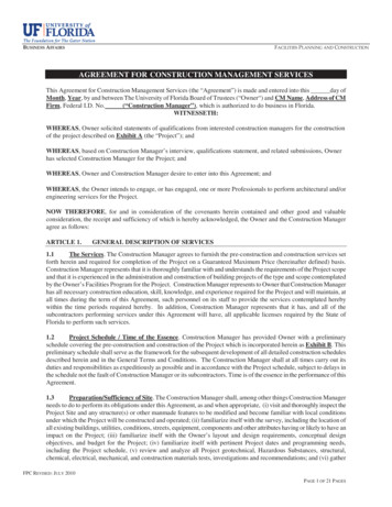
Proceedings of the International Society Of Flexible Formwork (ISOFF) Symposium 2015, Amsterdam16 - 17 August 2015, Amsterdam, The NetherlandsFigure 18, 19, 20, 21: 18) 2D base geometry, 19) 3D base geometry, 20) Physical model of elasticbands, 21) Form-finded model in GSAHowever this model was based on arches, some columns were too long. Buckling has much moreinfluence on longer columns so a new physical model was made using elastic bands in order to reducethe length of the columns. The elastic band model gives an indication of the form-finded design. Someropes were added to create a structure with shorter beams. Based on the physical elastic band modelan Autocad model was made.6.2.2. Form-findingThe final Autocad model was used to analyze the form-finding process in GSA. By varying forcedensities for certain ropes or parts and testing impacts of changing force density the final shape wasfound. Once the design was set, it was loaded with pre-stressed tensile forces to be able to test it onself-weight. Many small design changes have been made to optimize the structure. After changing thesupport points in a cyclic process the final model was found.6.2.3. Calculations & dimensionsWe assumed that the columns/beams will be tapered from bottom to top, because of the appliedbuilding method. The columns will be built up from the bottom, so more ice growth will occur on thelower parts of the columns. Water that is sprayed on the higher parts will flow downwards so waterwill pile up more in the lower construction, leaving a tapered column.The measurements of the nave are shown in Figure 22.Figure 22: Dimensions and thickness of the nave structure
Proceedings of the International Society Of Flexible Formwork (ISOFF) Symposium 2015, Amsterdam16 - 17 August 2015, Amsterdam, The Netherlands7. ConclusionBased on the previous experiments and experience with the construction of the Pykrete Dome it waspossible to build the highest ice dome of 21 meters in the winter of 2015. After having realized thisdome, samples have been made to test the material properties on compression. Because it was notpossible to drill cylinders out of the Pykrete dome, cubic samples of 90 x 90 x 90 mm were cut outwith a cha
The realization of the Sagrada Familia in Ice was completed in a 24/7 process by 4 teams who worked in shifts. The construction process requires a temperature of -8 C or lower. Four of the domes (2 x 21 meters and 2 x 18 meters) and the column structure of the nave were successfully constructed. The