Transcription
Engineering GraphicsEssentials with AutoCAD2014 Instruction Text and Video InstructionKirstie PlantenbergMultimedia DiscSDCP U B L I C AT I O N SBetter Textbooks. Lower Prices.www.SDCpublications.comVideo instruction,interactive quizesand more
Visit the following websites to learn more about this book:
Chapter 2: Orthographic ProjectionORTHOGRAPHIC PROJECTIONCHAPTER OUTLINE2.1) INTRODUCTION TO ENGINEERING GRAPHICS . 22.2) ORTHOGRAPHIC PROJECTION INTRODUCTION . 22.2.1) The six principle views . 32.3) THE GLASS BOX METHOD . 42.4) THE STANDARD VIEWS . 72.4.1) The front view . 72.5) LINE TYPES USED IN AN ORTHOGRAPHIC PROJECTION . 72.6) RULES FOR LINE CREATION AND USE . 92.6.1) Hidden lines . 92.6.2) Center lines . 102.6.3) Phantom lines . 122.6.4) Break lines . 142.6.5) Line type precedence . 142.7) CREATING AN ORTHOGRAPHIC PROJECTION. 152.7.1) Projection symbol. 162.8) AUXILIARY VIEWS . 30ORTHOGRAPHIC PROJECTION CROSSWORD PUZZLE. 35ORTHOGRAPHIC PROJECTION PROBLEMS. 372-1
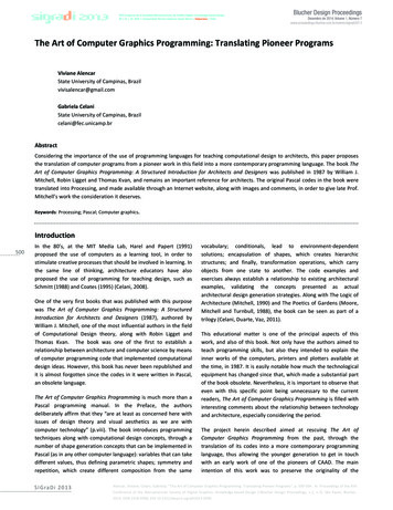
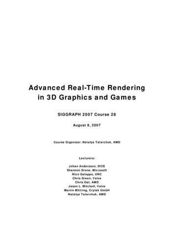
Chapter 2: Orthographic ProjectionCHAPTER SUMMARYIn Chapter 2 you will learn the importance of engineering graphics and how to create anorthographic projection. An orthographic projection describes the shape of an object. It is a twodimensional representation of a three dimensional object. Different line types are used to indicatevisible, hidden and symmetry lines. By the end of this chapter, you will be able to create atechnically correct orthographic projection using proper projection techniques.2.1) INTRODUCTION TO ENGINEERING GRAPHICSEngineering graphics is a set of rules and guidelines that help you create anengineering drawing. An engineering drawing is a drawing or a set of drawings thatcommunicates an idea, design, schematic, or model. Engineering drawings come inmany forms. Each engineering field has its own type of engineering drawings. Forexample, electrical engineers draw circuit schematics and circuit board layouts. Civilengineers draw plans for bridges and road layouts. Mechanical engineers draw partsand assemblies that need to be manufactured. This book focuses on the latter. This isnot to say that only students in a mechanical engineering curriculum will benefit fromlearning engineering graphics. It benefits everyone from the weekend carpenter whowants to draw plans for his/her new bookshelf to the electrical engineer who wants toanalyze electrical component cooling using a CAE program. Engineering graphicsteaches you how to visualize and see all sides of an object in your mind. Being able tovisualize in your mind will help you in several aspects of critical thinking.2.2) ORTHOGRAPHIC PROJECTION INTRODUCTIONAn orthographic projection enables us to represent a 3-D object in 2-D (seeFigure 2.2-1). An orthographic projection is a system of drawings that represent differentsides of an object. These drawings are formed by projecting the edges of the objectperpendicular to the desired planes of projection. Orthographic projections allow us torepresent the shape of an object using 2 or more views. These views together withdimensions and notes are sufficient to manufacture the part.2-2
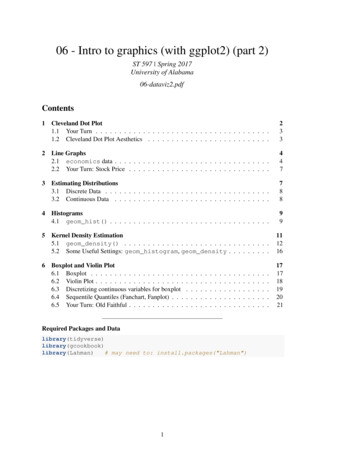
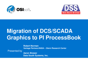
Chapter 2: Orthographic ProjectionFigure 2.2-1: Orthographic projection.2.2.1) The six principle viewsThe 6 principle views of an orthographic projection are shown in Figure 2.2-2.Each principle view is created by looking at the object in the directions indicated inFigure 2.2-2 and drawing what is seen as well as what is hidden from view.Figure 2.2-2: The six principle views.2-3
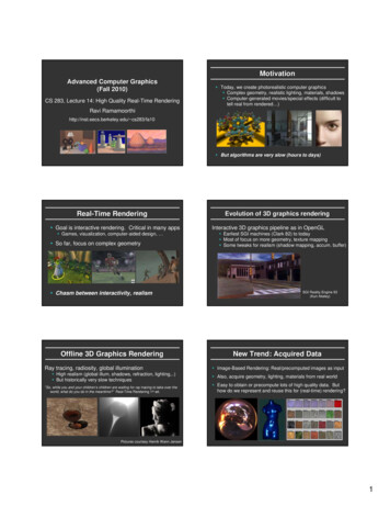
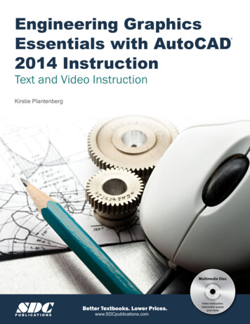
Chapter 2: Orthographic Projection2.3) THE GLASS BOX METHODTo obtain an orthographic projection, an object is placed in an imaginary glassbox as shown in Figure 2.3-1. The sides of the glass box represent the six principleplanes. Images of the object are projected onto the sides of the box to create the sixprinciple views. The box is then unfolded to lie flat, showing all views in a 2-D plane.Figure 2.3-2 shows the glass box being unfolded to create the orthographic projection ofthe object.Figure 2.3-1: Object in a glass box.2-4
Chapter 2: Orthographic ProjectionFigure 2.3-2: Glass box being unfolded.2-5
Chapter 2: Orthographic ProjectionInstructor Led Exercise 2.3-1: Principle viewsLabel the five remaining principle views with the appropriate view name.What are the differences between the Right Side and Left Side views?What are the differences between the Top and Bottom, and Front and Rear views?Which view(s) have the least number of hidden or dashed lines?2-6
Chapter 2: Orthographic Projection2.4) THE STANDARD VIEWSWhen constructing an orthographic projection, we need to include enough viewsto completely describe the true shape of the part. The more complex a part, the moreviews are needed to describe it completely. Most objects require three views tocompletely describe them. The standard views used in an orthographic projectionare the front, top, and right side views. The other views (bottom, rear, left side) areomitted since they usually do not add any new information. It is not always necessary touse the three standard views. Some objects can be completely described in one or twoviews. For example, a sphere only requires one view, and a block only requires twoviews.2.4.1) The front viewThe front view shows the most features or characteristics of the object. Itusually contains the least number of hidden lines. The exception to this rule is when theobject has a predefined or generally accepted front view. All other views are based onthe orientation chosen for the front view. The top, front, and bottom views are all alignedvertically and share the same width dimension. The left side, front, right side, and rearviews are all aligned horizontally and share the same height dimension (see the figureshown in Exercise 2.3-1).2.5) LINE TYPES USED IN AN ORTHOGRAPHIC PROJECTIONLine type and line weight provide valuable information to the print reader.For example, the type and weight of a line can answer the following questions: Is thefeature visible or hidden from view? Is the line part of the object or part of a dimension?Is the line indicating symmetry?There are four commonly used line types: continuous, hidden, center andphantom. The standard recommends using, no less than, two line widths. Importantlines should be twice as thick as the less important thin lines. Common thicknesses are0.6 mm for important lines and 0.3 mm for the less important lines. However, to furtherdistinguish line importance, it is recommended to use four different thicknesses orweights: thin, medium, thick, and very thick. The actual line thickness should be chosensuch that there is a visible difference between the line weights; however, they should notbe too thick or thin making it difficult to read the print. The thickness of the lines shouldbe adjusted according to the size and complexity of the part. The following is a list ofcommon line types and widths used in an orthographic projection.1. Visible lines: Visible lines represent visible edges and boundaries. The line type iscontinuous and the line weight is thick (0.5 - 0.6 mm).2. Hidden lines: Hidden lines represent edges and boundaries that cannot be seen.The line type is dashed and the line weight is medium thick (0.35 - 0.45 mm).3. Center lines: Center lines represent axes of symmetry and are important forinterpreting cylindrical shapes. Crossed center lines should be drawn at the centersof circles. They are also used to indicate circle of centers and paths of motion. Theline type is long dash – short dash and the line weight is thin (0.3 mm).2-7
Chapter 2: Orthographic Projection4. Phantom lines: Phantom lines are used to indicate imaginary features. Forexample, they are used to indicate the alternate positions of moving parts, andadjacent positions of related parts. The line type is long dash – short dash – shortdash and the line weight is usually thin (0.3 mm).5. Dimension and Extension lines: Dimension and extension lines are used to show thesize of an object. In general, a dimension line is placed between two extension linesand is terminated by arrowheads, which indicates the direction and extent of thedimension. The line type is continuous and the line weight is thin (0.3 mm).6. Cutting plane lines: Cutting plane lines are used to show where an imaginary cuthas been made through the object in order to view interior features. The line type isphantom and the line weight is very thick (0.6 to 0.8 mm). Arrows are placed atboth ends of the cutting plane line to indicate the direction of sight.7. Section lines: Section lines are used to show areas that have been cut by the cuttingplane. Section lines are grouped in parallel line patterns and usually drawn at a 45 angle. The line type is usually continuous and the line weight is thin (0.3 mm).8. Break lines: Break lines are used to show imaginary breaks in objects. A break lineis usually made up of a series of connecting arcs. The line type is continuous andthe line weight is usually thick (0.5 – 0.6 mm).Instructor Led Exercise 2.5-1: Line typesUsing the line type definitions, match each line type name with the appropriate linetype.2-8 Visible Line Hidden Line Center Line Phantom Line Dimension and Extension Lines Cutting Plane Line Section Lines Break Line
Chapter 2: Orthographic ProjectionInstructor Led Exercise 2.5-2: Line use in an orthographic projectionFill the following dotted orthographic projection with the appropriate line types.2.6) RULES FOR LINE CREATION AND USEThe rules and guide lines for line creation should be followed in order to createlines that are effective in communicating the drawing information. However, due tocomputer automation, some of the rules may be hard to follow.2.6.1) Hidden linesHidden lines represent edges and boundaries that cannot be seen.Rule 1. The length of the hidden line dashes may vary slightly as the size of thedrawing changes. For example, a very small part may require smaller dashesin order for the hidden line to be recognized.2-9
Chapter 2: Orthographic ProjectionRule 2. Hidden lines should always begin and end with a dash, except when the hiddenline begins or ends at a parallel visible line (see Figure 2.6-1).Figure 2.6-1: Drawing hidden lines.Rule 3. Dashes should join at corners (see Figure 2.6-2).Figure 2.6-2: Hidden lines at corner.2.6.2) Center linesCenter lines represent axes of symmetry and are important for interpretingcylindrical shapes (Figure 2.6-3). They are also used to indicate circle of centers andpaths of motion as shown in Figure 2.6-4.Figure 2.6-3: Axes of symmetry2 - 10
Chapter 2: Orthographic ProjectionFigure 2.6-4: Center line usesRule 1. Center lines should start and end with long dashes (see Figure 2.6-3).Rule 2. Center lines should intersect by crossing either the long dashes or the shortdashes (see Figure 2.6-5).Figure 2.6-5: Crossing center lines.2 - 11
Chapter 2: Orthographic ProjectionRule 3. Center lines should extend a short distance beyond the object or feature. Theyshould not terminate at other lines of the drawing (see Figure 2.6-6).Figure 2.6-6: Terminating center lines.Rule 4. Center lines may be connected within a single view to show that two or morefeatures lie in the same plane as shown in Figure 2.6-7. However, they shouldnot extend through the space between views.Figure 2.6-7: Connecting center lines.2.6.3) Phantom linesPhantom lines are used to indicate alternate positions of moving parts (seeFigure 2.6-4). They may also be used to indicate adjacent positions of related parts andrepeated detail as shown in Figures 2.6-8 and 2.6-9. They are also used to show filletsand rounds in the view that does not show the radius. In this case, the phantom linesare used to show a change in surface direction (see Figure 2.6-10).2 - 12
Chapter 2: Orthographic ProjectionRule 1. Phantom lines should start and end with a long dash.Figure 2.6-8: Related part.Figure 2.6-9: Repeated detail.Figure 2.6-10: Phantom lines used to indicated a change in surface direction2 - 13
Chapter 2: Orthographic Projection2.6.4) Break linesBreak lines are used to show imaginary breaks in an object. For example, whendrawing a long rod, it may be broken and drawn at a shorter length as shown in Figure2.6-11.Figure 2.6-11: Using break lines.There are two types of break lines. A break lin
Phantom lines: Phantom lines are used to indicate imaginary features. For example, they are used to indicate the alternate positions of moving parts, and adjacent positions of related parts. The line type is long dash – short dash – short dashand the line weight is usually thin(0.3 mm). 5.