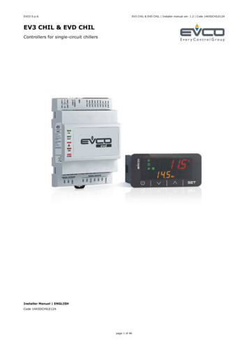
Transcription
EVCO S.p.A.EV3 CHIL & EVD CHIL Installer manual ver. 1.2 Code 1443DCHILE124EV3 CHIL & EVD CHILControllers for single-circuit chillersInstaller Manual ENGLISHCode 1443DCHILE124page 1 of 46
EVCO S.p.A.EV3 CHIL & EVD CHIL Installer manual ver. 1.2 Code 1443DCHILE124ImportantRead this manual carefully before installation and before usingthe devices and take all the prescribed precautions. Keep thismanual with the devices for future consultation.Only use the devices in the ways described in this manual. Donot use these devices as safety devices.DisposalThe devices must be disposed of according to local regulationsgoverning the collection of electrical and electronic waste.page 2 of 46
EVCO S.p.A.EV3 CHIL & EVD CHIL Installer manual ver. 1.2 Code 1443DCHILE124Index1INTRODUCTION . 41.1Introduction . 41.2Models available, purchasing codes and technical features . 52DESCRIPTION . 72.1Description of EV3 CHIL . 72.2Description of EVD CHIL . 82.3Description of EV3K01 . 93MEASUREMENTS AND INSTALLATION .103.1Measurements and installation of EV3 CHIL .103.2Measurements and installation of EVD CHIL .103.3Measurements and installation of EV3K01 .123.4Installation precautions .124ELECTRICAL CONNECTION .134.1I/O configuration .134.2Description of connectors .144.2.1 Description of connectors for EV3 CHIL .144.2.2 Description of connectors for EVD CHIL .164.2.3 Description of EV3K01 connectors .184.3Fitting the termination resistor to the RS-485 MODBUS slave port .194.4Example of electrical connection .204.4.1 Example of EV3 CHIL electrical connection .204.4.2 Example of EVD CHIL electrical connection .214.5Precautions for electrical connection .225DESCRIPTION OF USER INTERFACE .235.1Key functions .235.2Display .235.3Signals .245.4Menu.265.4.1 Access levels .265.4.2 Menu list .266LIST OF PARAMETERS .276.1Initial information .277REGULATORS .317.1Compressors .317.1.1 Oil refresh .327.2Hydraulic pump .337.2.1 Initial information .337.2.2 Function modes .337.2.3 Antifreeze function .337.3Condensation control.348ALARMS.358.1Initial information .358.2List of alarms .359ACCESSORIES .379.1EVIF20SUXI non-optoisolated RS-485/USB serial interface.379.1.1 Initial information .379.20025100010 drip protector .379.2.1 Initial information .379.3CJAV connection kit.379.3.1 Initial information .3710TECHNICAL SPECIFICATIONS .3810.1Technical specifications .38page 3 of 46
EVCO S.p.A.EV3 CHIL & EVD CHIL Installer manual ver. 1.2 Code 1443DCHILE1241INTRODUCTION1.1IntroductionEV3 CHIL and EVD CHIL are controllers for running singlecircuit air-water and water-water chillers with up to twocompressors.EV3 CHIL is available in the standard 74x32mm format withbuilt-in user interface consisting of a double custom display,with decimal point and function icons, and four touch keys. Itguarantees IP65 protection for easy cleaning.EVD CHIL is available in standard 4-module DIN format, in ablind version that can be connected to a remote user interface(EV3K01) if required.These controllers are capable of running compressors and fansof both the on-off and modulating types.EV3 CHIL is available with a 12VAC power supply, while EVDCHIL can be supplied with a 115. 230VAC power supply.EV3 CHIL is designed to be installed on a panel with snap-inbrackets, while EVD CHIL is fitted to a DIN rail in a controlpanel.page 4 of 46
EVCO S.p.A.1.2EV3 CHIL & EVD CHIL Installer manual ver. 1.2 Code 1443DCHILE124Models available, purchasing codes and technical featuresThe table below shows the models available, the purchasing codes and the technical features of the devices.COMPACT VERSIONModels available Purchasing codes SPLIT VERSIONEV3 CHILEV3904LM2EV3906LM2GFEVD CHILEV3K01EVD904BM9EV3K01XOCTVersionBlindBuilt-in LED (4 4 digit custom display) Micro-Fit connectors Edge connectors Plug-in screw terminal blocks Connections Power supply12VAC not insulated12VAC/DC not insulated 115 - 230VAC insulated Analogue inputsNTC333NTC/4-20 mA111666222Digital inputsDry contactAnalogue outputs0-10V/phase cutting/PWMpage 5 of 46
EVCO S.p.A.EV3 CHIL & EVD CHIL Installer manual ver. 1.2 Code 1443DCHILE124COMPACT VERSIONModels available Purchasing codes SPLIT VERSIONEV3 CHILEV3904LM2EV3906LM2GFEVD CHILEV3K01EVD904BM9EV3K01XOCTDigital outputs (electro-mechanical relays; A res. @ 250 VAC)2A SPST443A SPST28A SPDT112A SPST1Digital outputs (triac; A res. @ 250 VAC)200mA12A1Digital outputs (open collector)12VDC, max. 40mA1Communications portsPowered INTRABUS Other featuresAlarm buzzer NotesOptional extrasNone-Clock (not available for model To run 2 compressors models EV3906LM2GF and EVD904BM9 must be used.The purchasing codes for EV3 CHIL and EVD CHIL do not include the cabling connectors, see the ACCESSORIES section.For more models contact the EVCO sales network.page 6 of 46formodel
EVCO S.p.A.EV3 CHIL & EVD CHIL Installer manual ver. 1.2 Code 1443DCHILE1242DESCRIPTION2.1Description of EV3 CHILThe picture below shows the layout of the EV3 CHIL.The table below describes each part of the EV3 CHIL.PARTDESCRIPTION1Double row LED display, with decimal point and function icons2On/Off key, subsequently also called the On/Stand-by key3Decrease key, subsequently also called the Down key4Increase key, subsequently also called the Up key5Setting key, subsequently also called the Set key6Micro-switch for the termination of the RS-485 MODBUS line7Seal89Edge connector joint for the digital output cabling with electro-mechanical relay (for future reference, the digital outputsDO1. DO4)Male Micro-Fit connector for cabling for the power supply, analogue inputs, digital inputs, analogue outputs and theINTRABUS powered port10If fitted, plug-in screw terminal block for the RS-485 MODBUS port cabling11If fitted, the joint of the Edge connector for the triac digital output cabling (for future reference, the digital output TK1).12If fitted, the joint of the Edge connector for the triac digital output cabling (for future reference, the digital output TK2)For more information see subsequent sections.page 7 of 46
EVCO S.p.A.2.2EV3 CHIL & EVD CHIL Installer manual ver. 1.2 Code 1443DCHILE124Description of EVD CHILThe picture below shows the layout of the EVD CHIL.The table below describes each part of the EVD CHIL.PART1DESCRIPTIONMale Micro-Fit connector for cabling for analogue inputs, digital inputs, analogue outputs and the open collector digitaloutput (for future reference, the digital output OC1)2Micro-switch for the termination of the RS-485 MODBUS port3If fitted, plug-in screw terminal block for the RS-485 MODBUS port cabling4Plug-in screw terminal block for cabling for the powered INTRABUS port56Plug-in screw terminal block for cabling for the digital outputs with electro-mechanical relay (for future reference, thedigital outputs DO1 and DO2)Plug-in screw terminal block for cabling for the power supply, electrical-mechanical relay digital outputs (for futurereference, the digital outputs DO3 and DO4)For more information see subsequent sections.page 8 of 46
EVCO S.p.A.2.3EV3 CHIL & EVD CHIL Installer manual ver. 1.2 Code 1443DCHILE124Description of EV3K01The picture below shows the layout of the EV3K01.The table below describes each part of the EV3K01.PARTDESCRIPTION1Double row LED display, with decimal point and function icons2On/Off key, subsequently also called the On/Stand-by key3Decrease key, subsequently also called the Down key4Increase key, subsequently also called the Up key5Setting key, subsequently also called the Set key6Seal7Male female plug-in screw terminal block for cabling for the power supply and the powered INTRABUS port8Not usedFor more information see subsequent sections.page 9 of 46
EVCO S.p.A.EV3 CHIL & EVD CHIL Installer manual ver. 1.2 Code 1443DCHILE1243MEASUREMENTS AND INSTALLATION3.1Measurements and installation of EV3 CHILThe pictures below show the measurements of EV3 CHIL; measurements are expressed in mm (inches).To be installed on a panel with snap-in brackets provided.The thickness of the panel on which EV3 CHIL is to be installed must be between 0.8 and 2.0mm (0.031 and 0.078 in).3.2Measurements and installation of EVD CHILThe picture below shows the measurements of EVD CHIL (4 DIN modules); measurements are expressed in mm (inches).page 10 of 46
EVCO S.p.A.EV3 CHIL & EVD CHIL Installer manual ver. 1.2 Code 1443DCHILE124Installation is on a DIN rail 35.0 x 7.5mm (1.377 x 0.295 in) or 35.0 x 15.0mm (1.377 x 0.590 in), in a control panel.The pictures below show how to install the EVD CHIL.12To remove the EVD CHIL, first remove any plug-in screw terminal blocks fitted in the lower part, then, using a screwdriver, loosen theDIN rail clip, as shown in the pictures below.34To re-install the EVD CHIL first press the DIN rail clip fully in.page 11 of 46
EVCO S.p.A.3.3EV3 CHIL & EVD CHIL Installer manual ver. 1.2 Code 1443DCHILE124Measurements and installation of EV3K01The pictures below show the measurements of EV3K01; measurements are expressed in mm (inches).To be installed on a panel with snap-in brackets provided.The thickness of the panel on which the EV3K01 is to be installed must be between 0.8 and 2.0mm (0.031 and 0.078 in).3.4-Installation precautionsEnsure that the working conditions for the devices (operating temperatures, humidity, etc.) are within the set limits. Seethe section TECHNICAL SPECIFICATIONS.-Do not install the devices close to heat sources (heating elements, hot air ducts, etc.), equipment with a strong magneticfield (large diffusers, etc.), in places subject to direct sunlight, rain, damp, excessive dust, mechanical vibrations or shocks.-In compliance with safety regulations, the devices must be installed properly to ensure adequate protection from contactwith electrical parts. All protective parts must be fixed in such a way as to need the aid of a tool to remove them.page 12 of 46
EVCO S.p.A.EV3 CHIL & EVD CHIL Installer manual ver. 1.2 Code 1443DCHILE1244ELECTRICAL CONNECTION4.1I/O configurationThe table below shows the I/O configuration.ANALOGUE INPUTSIN1EV3904LM2EV3906LM2GFEVD904BM9 Condensation temperature/pressure (NTC/4-20mA)IN2Input water temperature (NTC) IN3Output water temperature (NTC) IN4Compressor discharge temperature (NTC) EV3904LM2EV3906LM2GFEVD904BM9System flow switch (NC) On/Off Fan thermal protection Compressor 1 thermal protection (NC) Maximum pressure switch (NC) Minimum pressure switch (NC) EV3904LM2EV3906LM2GFEVD904BM9DIGITAL INPUTSIN5IN10 (EVD)IN6 (EV3)IN9 (EVD)IN7 (EV3)IN8IN7 (EVD)IN9 (EV3)IN6 (EVD)IN10 (EV3)ANALOGUE OUTPUTSAO1Compressor 1 (0-10 V/phase cutting/PWM) AO2Fan (0-10 V/phase cutting/PWM) EV3904LM2EV3906LM2GFEVD904BM9DIGITAL OUTPUTSDO1Alarm DO2Enable fan DO3Circulation pump DO4Enable compressor 1 TK1Compressor 2 page 13 of 46
EVCO S.p.A.EV3 CHIL & EVD CHIL Installer manual ver. 1.2 Code 1443DCHILE124TK2FanOC1Compressor 24.2Description of connectors4.2.1Description of connectors for EV3 CHIL The picture below shows the layout of the EV3 CHIL connectors.The tables below describe the EV3 CHIL connectors.Connector 1PARTDESCRIPTION1Electro-mechanical relay digital outputs DO1. DO4 (max. 6A): common2Electro-mechanical relay digital output DO4 (2A SPST): normally open3Electro-mechanical relay digital output DO3 (2A SPST): normally open4Electro-mechanical relay digital output DO2 (2A SPST): normally open5Electro-mechanical relay digital output DO1 (2A SPST): normally openConnector 2PARTDESCRIPTION1Dry contact digital input IN62Analogue input IN1 (NTC/4-20 mA)3Dry contact digital input IN74Analogue input IN2 (NTC)5Dry contact digital input IN8page 14 of 46
EVCO S.p.A.EV3 CHIL & EVD CHIL Installer manual ver. 1.2 Code 1443DCHILE1246Analogue input IN3 (NTC)7Dry contact digital input IN98Analogue input IN4 (NTC)9Volt-free contact digital input IN1010Digital input IN511Analogue output AO1 (0-10 V/phase cutting/PWM)12Reference (GND) for analogue inputs, digital inputs, analogue outputs and powered INTRABUS port13Analogue output AO2 (0-10 V/phase cutting/PWM)14INTRABUS port powered up signal15Power supply to analogue inputs 4-20 mA (12 VDC, max. 40 mA)16Reference (GND) for analogue inputs, digital inputs, analogue outputs and powered INTRABUS port17EV3 CHIL power supply (12VAC not insulated)18EV3 CHIL power supply (12VAC not insulated)Connector 3 (if installed)PARTDESCRIPTION1RS-485 MODBUS port: 2RS-485 MODBUS port: -3RS-485 MODBUS port: reference (GND). NB: do not connect the cable shield.Connector 4 (if installed)PARTDESCRIPTION1Triac TK1 output: GND2Triac TK1 output (200 mA): OUTConnector 5 (if installed)PARTDESCRIPTION1Triac TK2 output: GND2Triac TK2 output (2 A): OUTpage 15 of 46
EVCO S.p.A.4.2.2EV3 CHIL & EVD CHIL Installer manual ver. 1.2 Code 1443DCHILE124Description of connectors for EVD CHILThe picture below shows the layout of the EVD CHIL connectors.The tables below describe the EVD CHIL connectors.Connector 1PARTDESCRIPTION1Electro-mechanical relay digital output DO1 (3A SPST): normally open2Electro-mechanical relay digital output DO2 (3A SPST): normally open3Electro-mechanical relay digital outputs DO1 and DO2 (max. 6A): commonConnector 2PARTDESCRIPTION1Electro-mechanical relay digital output DO3 (12A SPST): normally open2Electro-mechanical relay digital output DO3 and D04: common3Electro-mechanical relay digital output DO3 and D04: common4Electro-mechanical relay digital output DO4 (8A SPDT): normally open5Electro-mechanical relay digital output DO4 (8A SPST): normally closed7EVD CHIL power supply (115. 230 VAC insulated)8EVD CHIL power supply (115. 230 VAC insulated)page 16 of 46
EVCO S.p.A.EV3 CHIL & EVD CHIL Installer manual ver. 1.2 Code 1443DCHILE124Connector 3PARTDESCRIPTION1Analogue output AO2 (0-10 V/phase cutting/PWM)2Analogue outlet AO1 (0-10 V/phase cutting/PWM)3Reference (GND) for analogue inputs, digital inputs, analogue outputs and powered INTRABUS port4Analogue input IN1 (NTC/4-20 mA)5Dry contact digital input IN106Analogue input IN2 (NTC)7Dry contact digital input IN98Analogue input IN3 (NTC)9Dry contact digital input IN810Analogue input IN4 (NTC)11Dry contact digital input IN712Digital input IN513Reference (GND) for analogue inputs, digital inputs and analogue outputs14Dry contact digital input IN615Reference (GND) for analogue inputs, digital inputs and analogue outputs16power supply for analogue inputs 4-20mA (12 VDC, max. 120mA)17Open collector digital output OC1 (12V, max. 40mA)18Reference (GND) for analogue inputs, digital inputs and analogue outputspage 17 of 46
EVCO S.p.A.EV3 CHIL & EVD CHIL Installer manual ver. 1.2 Code 1443DCHILE124Connector 4 (if installed)PARTDESCRIPTION1RS-485 MODBUS port: reference (GND)2RS-485 MODBUS port: -3RS-485 MODBUS port: Connector 5PARTDESCRIPTION1reference (GND) for EV3K01 power supply and powered INTRABUS port2INTRABUS port powered up signal3EV3K01 power supply4.2.3Description of EV3K01 connectorsThe picture below shows the layout of the EV3K01 connectors.The table below describes the EV3K01 connectors.Connector 1PARTDESCRIPTION1EV3K01 (12 VAC/DC) power supply; if EV3K01 is fed by DC power, connect the positive pole2Not used3INTRABUS port powered up signal4reference (GND) for EV3K01 power supply and powered INTRABUS portpage 18 of 46
EVCO S.p.A.4.3EV3 CHIL & EVD CHIL Installer manual ver. 1.2 Code 1443DCHILE124Termination of the RS-485 MODBUS lineTo reduce reflections on the signal transmitted along the cables connecting the devices to a RS-485 network it is necessary toterminate the line ONLY at the first and last element in the network.To terminate the line, it will be sufficient to place EV3 CHIL micro-switch 1 in position ON. Do not touch micro-switch 2.When using EVD CHIL, place micro-switch 1 in position ON.page 19 of 46
EVCO S.p.A.EV3 CHIL & EVD CHIL Installer manual ver. 1.2 Code 1443DCHILE1244.4Example of electrical connection4.4.1Example of EV3 CHIL electrical connectionThe picture below shows an example of the EV3 CHIL electrical connection.If using triac digital outputs, we recommend connecting a noise filter. The heat sink might reach very high temperatures, do not touchit.page 20 of 46
EVCO S.p.A.4.4.2EV3 CHIL & EVD CHIL Installer manual ver. 1.2 Code 1443DCHILE124Example of EVD CHIL electrical connectionThe picture below shows an example of the EVD CHIL electrical connection.page 21 of 46
EVCO S.p.A.EV3 CHIL & EVD CHIL Installer manual ver. 1.2 Code 1443DCHILE1244.5Precautions for electrical connection-Do not use electric or pneumatic screwdrivers on the terminal blocks of the devices.-If the devices have been moved from a cold to a warm place, the humidity may cause condensation to form inside. Waitabout an hour before switching on the power.-Make sure that the supply voltage, electrical frequency and power of the devices correspond to the local power supply. Seethe section TECHNICAL SPECIFICATIONS.-Disconnect the devices from the power supply before doing any type of maintenance.-The devices must be fed by power of the same phase as that feeding any module with a phase-cutting command signal.-If using triac digital outputs, we recommend connecting a noise filter. The heat sink might reach very high temperatures,do not touch it.-Connect the devices to an RS-485 network using a screened cable with twisted pair for the signal and a third separateconductor for the reference (for example the BELDEN 3106A cable). NB: do not connect the cable shield to the reference(GND)-Connect the power cables as far away as possible from those for the signal.-Do not use the devices as safety devices.-For repairs and for further information on the devices, contact the EVCO sales network.page 22 of 46
EVCO S.p.A.EV3 CHIL & EVD CHIL Installer manual ver. 1.2 Code 1443DCHILE1245DESCRIPTION OF USER INTERFACE5.1Key functionsThe table below shows the functions of the keys.ICONNAMEOn/stand-bySetFUNCTION-Prolonged pressure will switch on / switch off the device-In set-parameters mode, it functions as a “Back” key-Prolonged pressure makes it possible to enter or exit the set-up menu (SEtP menu)-Press once to modify the set-point and confirm it.-It functions as the “Enter” key in menu navigation.In set-parameters mode:Up-It enables you to move to a higher menu-It enables you to increase the value of a parameterIn set-parameters mode:Down5.2-It enables you to move to a lower menu-It enables you to decrease the value of a parameter-Prolonged pressure enables you to view the measurements found by the probes.DisplayA pressure on the On/ stand-by will switch on / switch off the device. When the device is switched on with the key, it is possible toswitch it remotely to Stand-By mode by operating on the dedicated digital input through a switch.The user interface has two display modes.Initial display mode-The upper row shows the input water temperature, while the lower row shows the output water temperature or any alarmsactivated.-When the device is switched on with the key but remotely put to Stand-By mode, the label “oFFd” will be displayed on thelower row.-When the device is switched off with the key, the label “OFF” will be displayed on the upper row, while the time will bedisplayed on the lower row (if RTC is present and enabled, otherwise 4 lines ---- will be displayed.Menu display mode-What is displayed depends upon the menu level you are in, using a directory tree system in which the lower row shows asubcategory of the one shown on the upper row. To help users to identify what is being displayed, labels and codes areused, see paragraph 5.4.2.page 23 of 46
EVCO S.p.A.5.3EV3 CHIL & EVD CHIL Installer manual ver. 1.2 Code 1443DCHILE124SignalsThe table below shows the meaning of the LED signals of EV3 CHIL.LEDCOLOURMEANINGController LEDIt is dependant on parameter CF06 (default 0)GREEN0 cooling ON1 cooling ONCompressor 1 LEDGREEN-ON if the compressor is switched on-OFF if the compressor is switched off-BLINK if some timings are underwayCompressor 2 LEDGREEN-ON if the compressor is switched on-OFF if the compressor is switched off-BLINK if some timings are underwayHydraulic pump LEDGREEN-ON if the pump is switched on-OFF if the pump is switched offCondenser fan LEDGREENAMBERAMBERAMBER-ON if the fan is switched on-OFF if the fan is switched offLED for the unit of measurement of the value shown on the lower display when the probe isconfigured for temperatureLED for the unit of measurement of the value shown on the lower display when the probe isconfigured for pressureRun LEDAlarm LEDRED-ON if an alarm is underway-OFF if no alarm is underwaySet-up LEDRED-ON if the device is not showing the initial display-OFF during normal functioningOn/stand-by LEDREDRED-ON if the controller is switched off (at the same time as the “OFF” display signal)-OFF if the controller is switched onLED for the unit of measurement of the value shown on the upper display when the probe isconfigured for temperaturepage 24 of 46
EVCO S.p.A.LEDEV3 CHIL & EVD CHIL Installer manual ver. 1.2 Code 1443DCHILE124COLOURREDMEANINGLED for the unit of measurement of the value shown on the upper display when the probe isconfigured for pressureIB/RS485 LEDRED-BLINK if an INTRABUS/RS485 communication is underway-OFF if no communication is underwayThe table below shows the meaning of the LED signals of EVD CHIL.LEDCOLOREONGREENSIGNIFICATOPower supply LED-ON if the controller is powered-OFF if the controller is not powered“RUN” LEDRUNGREEN-ON if the controller is switched on-OFF if the controller is switched offAlarm LED RED-ON if an alarm is underway-OFF if no alarm is underwayINTRABUS LEDIBAMBER-BLINK if an INTRABUS communication is underway-OFF if no communication is underwayRS-485 LEDRS485AMBER-BLINK if an RS-485 communication is underway-OFF if no communication is underwaypage 25 of 46
EVCO S.p.A.EV3 CHIL & EVD CHIL Installer manual ver. 1.2 Code 1443DCHILE1245.4Menu5.4.1Access levelsThere are three access levels for navigating within the menus, two of which require a password:USUser: always visibleServicer: visible if the servicer password (parameter CF09, default -12) or the manufacturer password (parameter CF10,default -123) have been enteredMManufacturer: visible if the manufacturer password (parameter CF10, default -123) has been entered.5.4.2Menu listThe following menus are available:SEtPFor rapid access to the adjustment set-pointsProbShows the temperature or pressure valu
EVCO S.p.A. EV3 CHIL & EVD CHIL Installer manual ver. 1.2 Code 1443DCHILE124 page 2 of 46 Important Read this manual carefully before installation and before using the devices and take all the prescribed precautions. Keep this manual with the devices for future consultation. Only use the devices in the ways described in this manual. Do
