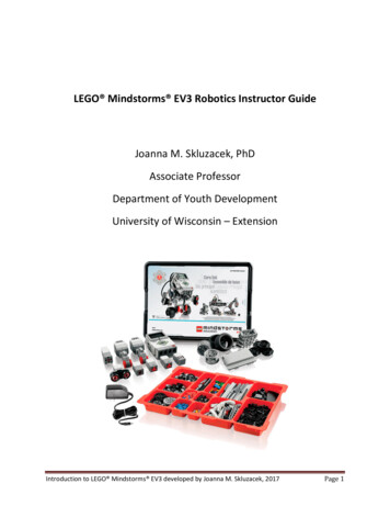
Transcription
Simple EV3 Wheelbotby Benjamin GoffCopyright Maine Robotics 2014Version 1.0 Beta1
Parts List Pt 1Electronics(1) EV3 Robot Controller(2) Mindstorm Wires, any size(2) Large EV3 MotorsWheels(2) Large WheelsORNote: the exact type of wheeldoes not matter, but the twowheels must be identical!The instructions will be usingthe bottom left wheels, butfeel free to experiment withdifferent wheelsParts Pictures from Bricklink.com(2) Small Pulley Wheels2
Parts List Pt 2Beams / Technic Lift Arms(2) 3x5-Hole L ShapedBent Technic Lift Arms(5) 5-Hole Technic Lift Arms(2) 7-Hole Technic Lift Arms(2) 2x4-Hole L ShapedBent Technic Lift Arms(2) 11-Hole Technic Lift ArmsAxle Connectors(1) Hole-Hole-Axle Connector,Perpendicular(1) Axle-Hole-Axle Connector,PerpendicularParts Pictures from Bricklink.com3
Parts List Pt 3AxlesNote: Axles are measured by the number ofstuds long they are. So a #7 Axle is 7 studslong if it is held next to a regular Lego brick.(1) #3 Axle(3) #7 AxlesPins and Connectors(4) Long Pins w/ Bushings(any color)(7) Black or Blue Long Pins(18 ) Black Friction Pins(2) Axle Pins(1) Half Bushing(5 ) BushingsParts Pictures from Bricklink.com4
Parts Laid Out5
1. BottomLay out pieces as shown and push together, lining up holes on the Lift ArmsBuild Base Pt11.2.Build Bottom: Connect the(5) 5-hole Technic Lift Armsusing the Long Pins.Build Back HorizontalReinforcers: Connect FrictionPins to (2) 11-hole Technic LiftArms as shown in the lowerright hand figure.2. Back Horizontal Reinforcers6
Build Base Pt23.4.Attach Bottom pieces andBack Horizontal Reinforcersto Motors.Note: the Motors have beenplaced upside down in thepicture!The bottoms of the Motors are a light gray, if yousee white on top then flip the Motors over.7
Step 2 Order: Hole-Hole-Axle Connector,Bushing, Bushing, Half-Bushing, Axle-HoleAxle Connector, BushingBuild Pivot Wheel1.Layout Pieces:#7 AxleAxle-Hole-Axle ConnectorBushing(2) Axle-Pins#3 AxleHole-Hole-Axle Connector Half(3) Full Bushings(2) Pulley Wheels2.Slide Full Bushings, Half-Bushing, Hole-Hole-AxleConnector, and Axle-Hole-Axle Connector onto #7Axle. See upper right picture3.Attach Pulley Wheels and #3 Axle to Hole-HoleAxle Connector (to the end hole) and push AxlePins into Axle-Hole-Axle Connector.Axle-Pins8
Attach Pivot Wheel to BaseFlip the Base over so thatthe white tops of theMotor are showing!The Pivot Wheel should attach to the bottomBack Horizontal Reinforcer9
Upper wheelshows deeperimpression.Lower wheelshows theshallowerimpression.This sideshould face themotorsAttach Large Wheels(Drive Wheels)Build Wheel and Axle Assemblies: Put#7 Axle through Large Wheel and thenslide on bushing. Repeat for the otherwheel.2. Put the Wheel and Axle Assembliesthrough the center hole of the Motors.Note: some wheels have a deeperimpression on one side than the other. TheShallower side should face TOWARDS themotors.1.Older wheels may need a bushing on bothsides to hold the wheel on.10
Build Side Assemblies Pt 11.Lay out Pieces:(2) 2x4 L Shaped Bent Lift Arms(2) 7-Hole Lift Arms(2) 3x5 L Shaped Bent Lift Arms(4) Long Pins w/ Bushings(2) Axle-pins and (6) Black Friction Pins.Note: The pieces change color in betweenpictures, this is to make them easier to see.2. Connect pins as shown inimage on right.Note: the two side pieces aremirrored not identical.Long Pins w/ BushingsBlack Friction PinAxle-pinBlack Friction PinsBlack Friction Pins11
Build Side Assemblies Pt 2Attach 7-Hole Lift Arms to 3x5 L Shaped Bent Lift Arms. The 7-Hole LiftArms should cover 4 holes of the 5-hole arm of the L Shaped Lift Arms.See upper left image.4. Connect the 2x4 L Shaped Bent Lift Arms to the exposed ends of the 7Hole Lift Arms. The 7-Hole Lift Arm should cover 3 holes of the 4-holearm of the L Shaped Lift Arm.Note: The completed Side Assemblies should be mirrored and form an “S”shape when viewed from the side. A backwards “S” may also work.3.12
Attach Side Assemblies andEV31.Attach Side Assemblies to the “Necks”of the Motors, as seen in the pictureon the left. Note: Do not push LongPins w/ Bushings fully in yet.2.Connect EV3 by lining up top mostforward side holes with the top of theSide Assemblies and pushing in theLong Pins w/ Bushings.Note: The screen of the EV3 should be overthe back of the Motors and the portslabeled 1 through 4 should be facing thesame direction as the Large Drive Wheels.13
Attach Wires to Motors and EV31.2.3.Rotate the EV3 so you are looking at it from the backand can see ports A, B, C, and DConnect a wire to Port C of the EV3 and the left sidemotor.Connect a wire to Port B of the EV3 and the rightside motor.14
Complete!Note: The Long Pins w/Bushings are usedbecause they are easierto grab with fingers. Thismakes taking the EV3 offto replace batteriesslightly easier.15
EV3 1. Attach Side Assemblies to the "Necks" of the Motors, as seen in the picture on the left. Note: Do not push Long Pins w/ Bushings fully in yet. 2. Connect EV3 by lining up top most forward side holes with the top of the Side Assemblies and pushing in the Long Pins w/ Bushings. Note: The screen of the EV3 should be over