Transcription
Siemens Gas TurbineSGT5-4000FAdvanced performanceAnswers for energy.SGT5 4000F.indd Abs1:114.05.2008 14:18:07 Uhr
The SGT5-4000F –Designed for competitive power generationIncreasingly fierce competition fueledby deregulation and privatization isdictating ever lower power generationcosts. One approach to cost-cutting iseconomical plant operation centeringon low investment costs and in particular on lowest life-cycle costs.The SGT5-4000F – SiemensGas Turbine (SGT ) – ourhigh-performance workhorseis tailored to meet these requirements. With its innovative design, materials andthermodynamic processes,the SGT5-4000F ensures youa strong position in a competitive market.The machine is characterized by the use of a provenconcept:Two rotor bearingsCold-end generator driveBuilt-up rotor with Hirthserrations and central tieboltThe combination of thisproven design and innovative features results in:High efficiencyLow maintenance expenditureLong service lifeFast payback on investedcapitalBased on the standard designconcepts of our modularreference power plants forsingle-shaft and multi-shaftapplication we have definedseveral scope of suppliesaround the SGT5-4000F.These packages from component through SGT-PAC to thefull Turnkey scope support allyour needs. The intelligentwith a range of modules andoptions brings you benefitsin terms of deadlines andquality.Low investment costs perinstalled kilowatt2SGT5 4000F.indd Abs1:214.05.2008 14:18:17 Uhr
Siemens Gas Turbine*SGT5-4000FSGT5-3000ESGT-1000FGrid frequency (Hz)505050/60Gross power output (MW)29219168Gross efficiency (%)39.836.835.1Gross heat rate 5/1,068583/1,081Exhaust mass flow (kg/s)692512192Exhaust mass flow (lb/s)1,5261,129422Gross heat rate (Btu/kWh)Exhaust temperature ( C/ F)18.213.315.713x6x813x6x811x4x4.8**30830853 20***Pressure ratioLength x width x height (m)*Weight (t)*Standard design; ISO ambient conditions** Length incl. transmission*** Weight main frame transmissionThe SGT5-4000F gas turbine conceptbuilds on more than 40 years‘ experience with heavy-duty gas turbines atSiemens and Siemens Westinghouse.This is the solid technical foundation,on which innovative technology isbased. Consistent application of theaccumulated know-how on a widerange of disciplines was implemented.For instance, development and manufacture of this technology involvednot only aeroengine manufacturersbut also precision casting specialists,research institutes and technical universities.The task in hand was to ensuremaximum operating economy.The first crucial questions wehad to answer were:Does an appropriate technicalplatform for this developmentalready exist?Where do new solutions haveto be found?Today, the SGT5-4000F is proofthat it is possible to reconcileambitious economic and environmental targets – through:Effective use of resourcesLow NOx content of exhaustgasLowest CO2 emissionsThe key technical startingpoints:Compression and combustion.We had to push forward intonew thermodynamic rangesand higher combustion temperatures, while still fulfillingthe requirements for an easyto-service design and longintervals between major overhauls.3SGT5 4000F.indd Abs1:314.05.2008 14:18:30 Uhr
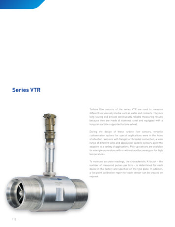
The compressorThe turbine bladesThe compressor withoptimized flow path andcontrolled diffusion airfoils for more efficientoperation. Ruggedizedcompressor design towithstand underspeedand overspeed conditions,ensuring reliable operationof the SGT5-4000F in gridswith major frequencyfluctuations.The blades of the first andsecond turbine stages haveto withstand thermalstresses and are thereforefabricated from a heatresistant alloy which isallowed to solidify as asingle-crystal structure.They also have an additionalceramic coating. They arecooled internally througha complex array of airchannels and externallyby film cooling. These measures combine to ensure along blade service life.The SGT5-4000F –Innovative design on a proven basisOptimized flow, combustion and cooling systems as well as new materialsadd up to a gas turbine efficiency ofnearly 40%. To highlight a few features:Very compact casing15-stage high-efficiencycompressorOptimized design point forcompressor pressure ratioand boundary-zone-corrected compressor blades(controlled diffusion airfoils)Annular combustionchamber with 24 hybridburners for uniform flowand temperature distributionCompact design and fullyceramic heat shields tominimize cooling air requirementsHigh-efficiency vortex andconvection cooling in theblade interior with filmcooling of the blade surfaceThe latest vintage SGT54000F also features fail-safehydraulic turbine blade tipclearance control for optimized radial clearances andhence maximimum performanceEasy-to-service designthanks to an annular walkin combustion chamber,which enables inspection ofhot-gas-path parts withoutcover liftSingle-crystal blades madeof high-grade alloys withadditional ceramic coating4SGT5 4000F.indd Abs1:414.05.2008 14:18:33 Uhr
The rotorThe rotor is designed as adisk-type rotor with Hirthserrations and central tiebolt. This proven designprinciple combines lowweight with high stiffnessand ensures smoothrunning and low thermalstresses under all operatingconditions, resulting in thefamiliar short run-up timesof Siemens gas turbines.The annularcombustion chamberThe enhanced hybridburner (HR3) with its cylindrical burner extensionsand modified flow pathresults in stable, low noisecombustion.Proven design features at a glanceThe SGT5-4000F is based onthe SGT5-2000E/SGT6-2000E,our reliable runners. Thesegas turbines are of provenruggedness, as attested bymore than 380 machines soldand more than 8.8 millioncumulative operating hours.Main features include:Horizontally split casingTwo rotor bearingsDisk-type rotor with Hirthserrations and a central tieboltAll blades removable withrotor in placeMulti-stage axial-flow compressor with variable-pitchinlet guide vanes, four-stageaxial-flow turbine, allmoving blades free-standingHybrid burners for premixand diffusion mode operation with natural gas andfuel oilCombustion chambers linedwith individually replaceable ceramic heat shieldsGenerator coupled to compressor (cold-end drive)Axial exhaust gas flowThe enhanced hybrid burnerThe dual-fuel hybrid burner for premixand diffusion combustion of gas and oilconsists of a system of rugged individualburners. This configuration permitsflexible, stable, clean – and thereforeeconomical – operation.5SGT5 4000F.indd Abs1:514.05.2008 14:18:37 Uhr
The SGT5-PAC 4000FThe Siemens Gas Turbine Package(SGT-PAC) comprises the gas turbineand generator, and all major mechanical, control and electrical equipmentrequired for safe and reliable operation of these components.We deliver our Siemens GasTurbine Packages largely preassembled, including pipingand wiring to a major extend.The auxiliary systems are combined in groups and installedas prefabricated packages.This reduces installation andcommissioning expendituresand durations.Pre-engineered options areavailable to meet project- andsite-specific requirements orto increase operating flexibility and performance of thepower generating system.Scope of SGT5-PAC 4000FBase scopeOptions (selection)Gas turbineLiquid fuel systemElectrical generatorDual-fuel operationFuel gas systemNOx water injectionsystem for liquid fuelsHydraulic oil systemInstrument air systemLube oil systemInlet air evaporativecoolingCompressor cleaningsystemInlet air anti-icingsystemAir intake systemInlet air self-cleaningpulse filterExhaust gas diffuserInstrumentation &ControlGas turbine stackfor simple cyclePower Control CentersDiverter damperand bypass stackfor combined cycleNoise enclosuresFurther noise abatementFire protectionFin-fan cooling systemsfor generator and lubeoilElectrical equipmentStarting frequencyconverter6SGT5 4000F.indd Abs1:614.05.2008 14:18:41 Uhr
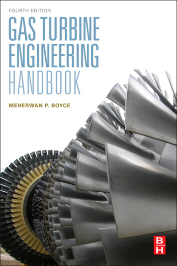
Didcot B, EnglandPerformance*Siemens Gas Turbine PackagesNet power output (MW)Net efficiency (%)Net heat rate (kJ/kWh)Net heat rate (Btu/kWh)Exhaust temperature ( C/ F)Exhaust mass flow (kg/s)Exhaust mass flow (lb/s)Generator typeSiemens Combined Cycle Power PlantSingle-ShaftNet power output (MW)Net efficiency (%)Net heat rate (kJ/kWh)Net heat rate (Btu/kWh)Multi-Shaft 2x1Net power output (MW)Net efficiency (%)Net heat rate (kJ/kWh)Net heat rate (Btu/kWh)* ISO conditions, natural gas fuelSGT5-4000F50 -3000E50 1000F50/60 onal Power plc. operatesthe combined cycle powerplant with two multi-shaft 2x1units that has a total capacityof 1390 MW and nearly220,000** operating hours forV94.3A (new: SGT5-4000F).Mainz-Wiesbaden, GermanyKraftwerke Mainz-WiesbadenAG operates the combinedcycle cogeneration powerplant with one multi-shaft 1x1unit that has a total capacityof 410 MW, featuring thelatest vintage V94.3A (new:SGT5-4000F) design alreadywith over 52,000** operatinghours.Seabank 1&2, EnglandWorld experienceThe SGT5-4000F has been in servicesince 1997. We have sold nearly 290gas turbines of the SGT-1000F series,SGT5-4000F and SGT6-4000F withmore than 3.6 million cumulativeoperating hours and a fleet reliabilityexceeding 99%.**Seabank Power Ltd./Scottish& Southern Energy operateone multi-shaft 2x1 and onesingle-shaft combined cyclepower plant with a totalcapacity of 1,140 MW andnearly 150,000** operatinghours.Genelba, ArgentinaPECOM ENERGIA S.A. operatesthe combined cycle powerplant with a multi-shaft 2x1unit that has a total capacity of660 MW and over 133,000**operating hours.** Status December 2007SGT5 4000F.indd Abs1:7714.05.2008 14:18:51 Uhr
rSGT5 4000F.indd Abs1:814.05.2008 14:18:57 Uhr
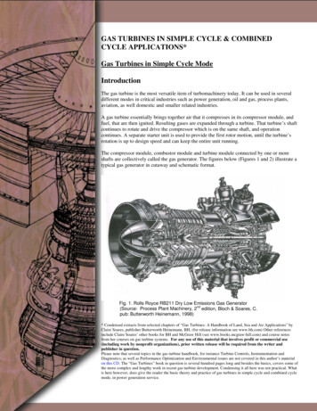
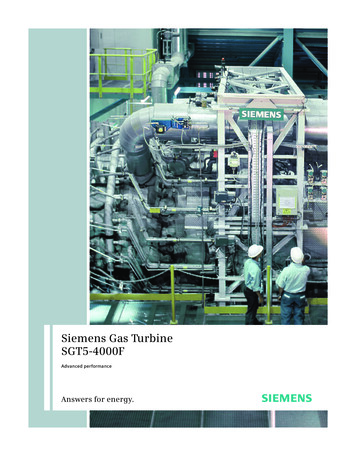
SGT5-4000F adjustmentto site conditionsPower Output and Efficiency at Generator Terminals1.121.08Efficiency atGenerator Terminals1.041.000.960.920.88Power Output atGenerator Terminals0.840.800.76-20-1001020304050Ambient temperature [ C]Power Output at Generator 120014001600Altitude [m]Power Output at Generator Terminals1.0081.0040 C15 C1.0000.99630 C0.99245 C0.988020406080100Relative humidity [%]Efficiency at Generator Terminals1.01245 C1.00830 C1.00415 C1.0000 C0.9960.992020406080100Relative humidity [%]SGT5 4000F.indd 914.05.2008 14:18:03 Uhr
Published by and copyright 2008:Siemens AGEnergy SectorFreyeslebenstrasse 191058 Erlangen, GermanySiemens Power Generation, Inc.4400 Alafaya TrailOrlando, FL 32826-2399, USAFor more information, contact ourCustomer Support Center.Phone: 49 180/524 70 00Fax: 49 180/524 24 71(Charges depending on provider)e-mail: support.energy@siemens.comFossil Power Generation DivisionOrder No. A96001-S90-B323-X-4A00Printed in GermanyDispo 05400, c4bs No. 1359, 805108411M WS 05083.Printed on elementary chlorine-free bleached paper.All rights reserved.Trademarks mentioned in this document arethe property of Siemens AG, its affiliates, or theirrespective owners.Subject to change without prior notice.The information in this document contains generaldescriptions of the technical options available, whichmay not apply in all cases. The required technicaloptions should therefore be specified in the contract.www.siemens.com/energySGT5 4000F.indd 1014.05.2008 14:18:06 Uhr
Application HandbookSGT5-PAC 4000F5Performance Summary5.1Performance Overview for ISO Conditions5.2Thermal Performance for Site-Specific Conditions5.3Performance Optimization5.4Emissions Performance5.5Start-up Performance5.6Steam Production Capability5.7Acoustic Performance5.8Online Fuel-Changeover5.9Generator Performance5.10Reliability and Availability5.11Combined-Cycle PerformanceTables1:2:3:4:Thermal Performance and Emissions OverviewStart-Up PerformanceAcoustic Performance - Surface Sound Pressure Levels and Sound Power LevelsReliability and 3:14:Ambient Pressure - Effect on Power Output, Mass FlowSite Elevation - Effect on Ambient PressureCompressor Inlet Temperature - Effect on Power Output, Efficiency, ExhaustTemperature, Mass FlowRelative Humidity - Effect on Power Output, Efficiency, Exhaust Temperature,Mass FlowInlet and Outlet Pressure Loss - Effect on Power Output, Efficiency, ExhaustTemperature, Mass FlowFuel Gas Lower Heating Value - Effect on Power Output, Efficiency, Mass FlowSpeed - Effect on Power Output, Efficiency, Exhaust Temperature, Mass FlowDegradation - Effect on Power Output, EfficiencyPart Load - Effect on Efficiency, Exhaust Temperature, Mass FlowNOx Emissions for Natural Gas Fuel in Premix Mode, Light Distillate Fuel inPremix Mode, Light Distillate Fuel in Premix Mode and Water InjectionStart-Up of Gas Turbine to Full LoadVariable-Pitch Inlet Guide Vane OperationSteam Production - Steam Production Capability, HRSG Steam RejectionOnline Fuel-Changeover – Gas to Oil, Oil to GasAir-Cooled Generator: Reactive Capability Curve, Saturation Curves, V-CurvesSiemens AG . Power Generationnon-binding values / informationTransmittal, reproduction, dissemination and/or editing of this document as well as utilizationof its contents and communication thereof to others without express authorization areprohibited. Offenders will be held liable for payment of damages. All rights created by patentgrant or registration of a utility model or design patent are reserved.Application Handbook SGT5-PAC 4000F I Revision 3 I 23.05.2007 I H. Bauer I Section 5 I Page 1 of 15
Application HandbookSGT5-PAC 4000F5 Performance Summary5.1Performance Overview for ISO conditionsBase load plant thermal performance and emissions performance under ISO conditions for astandard SGT5-PAC 4000F Siemens Gas Turbine Package is provided in Table 1.5.2Thermal Performance for Site-Specific ConditionsThis section provides a systematic method of determining the performance of a Siemens GasTurbine Package for specific site conditions. Five basic parameters are used to measurethermal plant performance: power outputefficiency or heat ratefuel mass flowturbine exhaust flowturbine exhaust temperaturecompressor mass flowConditions that directly affect thermal performance are site elevationcompressor inlet temperaturecompressor inlet and turbine exhaust lossesfuel gas lower heating valuerotor speeddegradationload levelUsing correction factors, the effects of site conditions on plant performance can be estimatedfor a variety of operating configurations. The performance data is presented for natural gasand liquid fuel for base loads. Net power is the power at the generator terminals minusPackage plant auxiliary loads. Net power and net heat rate are provided for an Gas TurbinePackage with an air-cooled generator.The thermodynamic design data at ISO conditions and base load can be approximatelyconverted to other ambient conditions using appropriate correction factors. Figures 1 - 8depict these correction factors as curves plotted as a function of the individual ambientconditions. Data calculated with these correction factors must not be used as guarantee data.Guarantee data for conditions other than ISO ambient conditions must be calculated with acycle calculation program specified by Siemens.Siemens AG . Power Generationnon-binding values / informationTransmittal, reproduction, dissemination and/or editing of this document as well as utilizationof its contents and communication thereof to others without express authorization areprohibited. Offenders will be held liable for payment of damages. All rights created by patentgrant or registration of a utility model or design patent are reserved.Application Handbook SGT5-PAC 4000F I Revision 3 I 23.05.2007 I H. Bauer I Section 5 I Page 2 of 15
Application HandbookSGT5-PAC 4000FPower Output at generator terminalsPGT-CORR PGT P*1 P*2 P*3 P*4 P*5 P*6 P*7 cted output at generator terminalsOutput at generator terminals under ISO conditionsCorrection factor for ambient pressureCorrection factor intake pressure dropCorrection factor for exhaust pressure dropCorrection factor for lower heating valueCorrection factor fur humidityCorrection factor for speedCorrection factor for ambient temperatureCorrection factor for agingEfficiency at generator terminalsηGT-CORR ηGT E*2 E*3 E*4 E*5 E*6 E*7 E*8 rected efficiency at generator terminalsEfficiency at generator terminals under ISO conditionsCorrection factor for intake pressure dropCorrection factor for exhaust pressure drop perCorrection factor for lower heating value 7Correction factor for humidityCorrection factor for speedCorrection factor for ambient temperatureCorrection factor for part load (at rated load, η*GT8 1.0)Correction factor for agingFuel MassmF-CORR Siemens AG . Power Generationnon-binding values / information.PGT-CORR/(ηGT-KORR LHV)Transmittal, reproduction, dissemination and/or editing of this document as well as utilizationof its contents and communication thereof to others without express authorization areprohibited. Offenders will be held liable for payment of damages. All rights created by patentgrant or registration of a utility model or design patent are reserved.Application Handbook SGT5-PAC 4000F I Revision 3 I 23.05.2007 I H. Bauer I Section 5 I Page 3 of 15
Application HandbookSGT5-PAC 4000FTurbine Exhaust Mass FlowmTDO-CORR. mTDO M*1 M*2 M*4 M*5 M*6 M*7 d turbine exhaust mass flowTurbine exhaust mass flow under ISO conditionsCorrection factor for ambient pressureCorrection factor for intake pressure dropCorrection factor for lower heating valueCorrection factor for humidityCorrection factor for speedCorrection factor for ambient temperatureCorrection factor for part load (at rated load, M*8 1.0)Turbine Exhaust TemperatureϑTDO-CORR. ϑTDO T*2 T*3 T*5 T*6 T*7 T*8whereϑTDO-CORRϑTDOT*2T*3T*5T*6T*7T*8Corrected turbine exhaust temperatureTurbine exhaust temperature under ISO conditions 1Correction factor for intake pressure dropCorrection factor for exhaust pressure dropCorrection factor for humidityCorrection factor for speedCorrection factor for ambient temperatureCorrection factor for part load (at rated load, T*8 1.0)Compressor Mass FlowmCI-CORR. mTDO-CORR - (1 mH2O / mF ) mF-CORRSiemens AG . Power Generationnon-binding values / informationTransmittal, reproduction, dissemination and/or editing of this document as well as utilizationof its contents and communication thereof to others without express authorization areprohibited. Offenders will be held liable for payment of damages. All rights created by patentgrant or registration of a utility model or design patent are reserved.Application Handbook SGT5-PAC 4000F I Revision 3 I 23.05.2007 I H. Bauer I Section 5 I Page 4 of 15
Application HandbookSGT5-PAC 4000F5.3Performance OptimizationGas Turbines may degrade in performance due to a number of factors such as: Deposits on flow surfacesRoughing of flow surfacesForeign object damageGross distortion of partsSeal and blade tip wearFigures 7 show the typically expected effect of degradation on power output and efficiencyrelated to a reference condition. This reference condition is, among other things, theguaranteed performance for „new and clean“ and operation of the gas turbine withconventional gaseous or liquid fuels. Furthermore the compliance with recommendations oncompressor cleaning must also be given (more details in Chapter “Auxiliary Systems”).The magnitude in performance recovery resulting from maintenance activities depends on thescope of the work (more details in Chapter “Service Aspects”). The curve for long-termdegradation depicts how performance is recovered after a major inspection has beenperformed, including manual compressor cleaning of all stages.The only degradation that is recoverable by cleaning is that due to removable deposits on flowsurfaces. These deposits cause increased friction and separation losses, and are not confinedto the compressor. The following deals only with compressor cleaning, but it is important torealize that the effectiveness of cleaning may not be noticed if the degradation due to theother factors becomes large. The degradation due to such wear and tear, however, should berecoverable at major overhaul with individual component restoration.Typical fouling characteristics in the compressor are due to a build-up of an oily/greasysurface in several early stages of the compressor flow path components. This surface, in turn,acts to trap other drier particulate matter, and a layering cycle begins to take place. Siemensrecommends both an on-line and an off-line cleaning to help recover losses in performancefrom these deposits. Compressor deposits can generally be removed by on-line cleaning torender partial restoration. Shutdown and off-line cleaning with a water-detergent solution willresult in relatively full restoration in most environments.The severity and rate of degradation, and hence the choice and frequency of the applicationof these procedures, depends upon the environment in which the engine is operating. Someunits are situated in environments that are more conductive to fouling than others. Forexample, in clean, in-land locations, the air is usually free of dust and binding agents (oilvapors, airborne chemicals, etc.). When the atmosphere is contaminated, more frequentcleaning is necessary to recover the lost efficiency. High efficiency, multi-stage inlet filtersmay help in certain applications. Turbine water cleaning is required only for ash producingfuels, such as crude and residual oil fuel.Siemens AG . Power Generationnon-binding values / informationTransmittal, reproduction, dissemination and/or editing of this document as well as utilizationof its contents and communication thereof to others without express authorization areprohibited. Offenders will be held liable for payment of damages. All rights created by patentgrant or registration of a utility model or design patent are reserved.Application Handbook SGT5-PAC 4000F I Revision 3 I 23.05.2007 I H. Bauer I Section 5 I Page 5 of 15
Application HandbookSGT5-PAC 4000F5.4Emissions PerformanceThe SGT5-4000F gas turbine includes dry low-NOx technology to control NOx emissions.Water injection to the fuel can be provided as an option to further reduce emissions whenoperating on fuel oil.Dry low NOx technology utilizes lean premix combustion in conjunction with a pilot zone. Theintense mixing and overall lean conditions result in lower flame temperatures and minimal NOxgeneration. The conventional diffusion-flame zone is used to meet the operationalrequirements of the gas turbine: ignition, fuel staging sequence through the engine loadrange, and flame stability.The NOx production of the combustor is a direct function of the amount of fuel that is burnt inthe pilot zone, where the fuel burns close to the stoichiometric flame temperature. At baseload firing temperature, over 90% of the fuel is burned in the lean, premixed zones.The NOx control performance is illustrated in Table 1 and Figures 9.Siemens AG . Power Generationnon-binding values / informationTransmittal, reproduction, dissemination and/or editing of this document as well as utilizationof its contents and communication thereof to others without express authorization areprohibited. Offenders will be held liable for payment of damages. All rights created by patentgrant or registration of a utility model or design patent are reserved.Application Handbook SGT5-PAC 4000F I Revision 3 I 23.05.2007 I H. Bauer I Section 5 I Page 6 of 15
Application HandbookSGT5-PAC 4000F5.5Start-Up PerformanceThe SGT5-PAC 4000F Siemens Gas Turbine Package has short start-up times which aredefined by the time needed to reach full rotor speed, time for synchronization and time toreach full load. Figure 10 shows a typical start-up profile.The procedure for automatic start-up and shutdown passes through the following sequence(for simple-cycle operation): If the gas turbine is not in turning gear operation mode, the lubrication oil system is startedand brought up to full pressure. The turbine-generator rotor is accelerated to turning gear speed of 120 rpm. The starting frequency converter then begins to accelerate the unit shaft. The gas ignition system is activated at 500 rpm. Minimum fuel (approximately 10 % flow) isadmitted to the gas turbine at about 700 rpm when the fuel stop valve is opened. At 1000 rpm the fuel flow is gradually increased to accelerate the unit shaft. The variable frequency converter is switched off at 2100 rpm. Further acceleration up tosynchronous speed of 3000 rpm is maintained by the turbine itself. Automatic synchronization with a stable electrical system is possible within approx.20 seconds. The loading procedure begins with a 5 MW load step. Subsequently, loading up to baseload can be accomplished at a constant gradient of 13 MW/min. Full exhaust-gas temperature is reached at about half load. Then the compressor variable-pitch guide vanes are modulated towards the fully openpositions at base load.The gas turbine is unloaded after shutdown command in accordance with the same gradientas for loading. There is no difference of the above described procedure in restarting from cold,warm or hot start conditions.The start-up performance is given in Table 2Siemens AG . Power Generationnon-binding values / informationTransmittal, reproduction, dissemination and/or editing of this document as well as utilizationof its contents and communication thereof to others without express authorization areprohibited. Offenders will be held liable for payment of damages. All rights created by patentgrant or registration of a utility model or design patent are reserved.Application Handbook SGT5-PAC 4000F I Revision 3 I 23.05.2007 I H. Bauer I Section 5 I Page 7 of 15
Application HandbookSGT5-PAC 4000F5.6Steam Production CapabilityVariable-Pitch Inlet Guide Vane ControlWhen operating the gas turbine in heat-recovery applications, it is generally desirable to holdthe turbine inlet temperature constant at part load to maintain a low plant heat rate. Toachieve this, the Siemens Gas Turbine utilizes variable inlet guide vanes.The flow of air through the gas turbine is controlled by adjusting the pitch of the compressorinlet guide vanes. When the inlet guide vanes are “opened“, the air flow through the gasturbine increases, when they are “closed“ it decreases. This makes it possible to maintain aconstant exhaust temperature in the upper output range when load changes are made. As aresult, the part-load efficiency of combined-cycle plants is improved.Figure 11 demonstrates how power and exhaust temperature are affected by opening theIGVs during start-up or closing the IGVs for part load operation. Below approximately 60% ofbase load, the inlet guide vanes cannot be closed any further, and a reduction in turbine inlettemperature must be used to lower power.CHP ApplicationsFitted with a heat-recovery steam-generator, the Siemens Gas Turbine Package can be usedin heat recovery applications to produce steam for industrial process use or for cogeneration(cogen), also known as combined heat and power (CHP). Cogen/CHP is the simultaneousproduction of electricity and useful heat from the same fuel or energy. A compilation of wasteheat recovery steam curves are provided in Figure 12. For this purpose a single-pressuresteam boiler has been used as a reference. Multiple-pressure steam cycle will be applicablefor cogen projects as well.The gas turbine performance data reflects the effects of a GT inlet pressure loss of 3.4'' H2O(approx. 9mbar) and GT outlet pressure drop of 11'' H2O (approx 27.4 mbar). All ratings arespecified for base load output at 15 C (59 F) sea level conditions on natural gas fuel.For this purpose the single-pressure steam boiler is configured with state-of-the-art valuescomponent performance:- Approach Point 10 F (5.5K)- Pinch Point 15 F (8.3K)- Pressure losses- Economizer 3%- Superheater 3%- Drum-Blow-Down 1%- Condensate Temperature 227.8 F (108.2 C)Although, steam production varies depending on site conditions, these steam curves willenable users to determine the amounts of steam that can be expected, at different pressureand temperature conditions, from ducting gas turbine exhaust into a single- pressure levelwaste heat recovery boiler without supplementary firing.Siemens AG . Power Generationnon-binding values / informationTransmittal, reproduction, dissemination and/or editing of this document as well as utilizationof its contents and communication thereof to others without express authorization areprohibited. Offenders will be held liable for payment of damages. All rights created by patentgrant or registration of a utility model or design patent are reserved.Application Handbook SGT5-PAC 4000F I Revision 3 I 23.05.2007 I H. Bauer I Section 5 I Page 8 of 15
Application HandbookSGT5-PAC 4000F5.7Acoustic PerformanceNear Field Sound LevelThe spatially averaged near field A-weighted sound level resulting from the operation of oneSiemens Gas Turbine Package is estimated to be as shown in Table 3 under the followingconditions: measured in a free field environment measured on the near field source envelope contour located 1 meter from major surfacesof equipment and/or enclosures, at a height of 1.5 meters above ground level Siemens Gas Turbine Package is operating at steady state base load conditions, exclusiveof transients, startup and shutdown, off-normal and emergency conditions, and pulse filtercleaning operations (if applicable)In the event the Siemens Gas Turbine Package scope of supply excludes exhaustcomponents, as in combined-cycle applications, the estimated sound levels given
The Siemens Gas Turbine Package (SGT-PAC) comprises the gas turbine and generator, and all major mechani-cal, control and electrical equipment required for safe and reliable opera-tion of these components. The SGT5-PAC 4000F We deliver our Siemens Gas Turbine Packages largely pre-assembled, including piping and wiring to a major extend.