Transcription
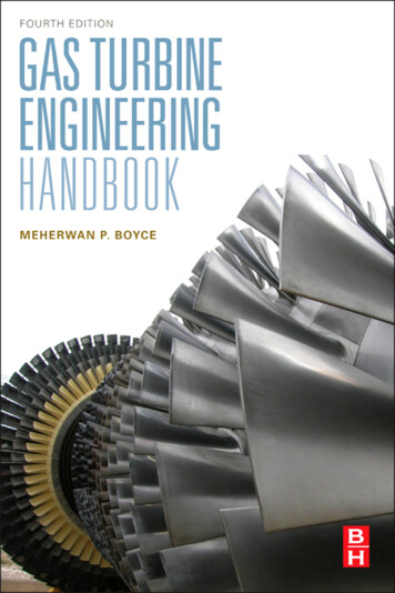
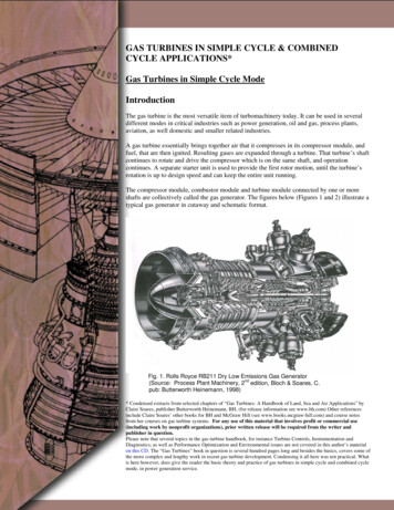
GAS TURBINES IN SIMPLE CYCLE & COMBINEDCYCLE APPLICATIONS*Gas Turbines in Simple Cycle ModeIntroductionThe gas turbine is the most versatile item of turbomachinery today. It can be used in severaldifferent modes in critical industries such as power generation, oil and gas, process plants,aviation, as well domestic and smaller related industries.A gas turbine essentially brings together air that it compresses in its compressor module, andfuel, that are then ignited. Resulting gases are expanded through a turbine. That turbine’s shaftcontinues to rotate and drive the compressor which is on the same shaft, and operationcontinues. A separate starter unit is used to provide the first rotor motion, until the turbine’srotation is up to design speed and can keep the entire unit running.The compressor module, combustor module and turbine module connected by one or moreshafts are collectively called the gas generator. The figures below (Figures 1 and 2) illustrate atypical gas generator in cutaway and schematic format.Fig. 1. Rolls Royce RB211 Dry Low Emissions Gas Generator(Source: Process Plant Machinery, 2nd edition, Bloch & Soares, C.pub: Butterworth Heinemann, 1998)* Condensed extracts from selected chapters of “Gas Turbines: A Handbook of Land, Sea and Air Applications” byClaire Soares, publisher Butterworth Heinemann, BH, (for release information see www.bh.com) Other referencesinclude Claire Soares’ other books for BH and McGraw Hill (see www.books.mcgraw-hill.com) and course notesfrom her courses on gas turbine systems. For any use of this material that involves profit or commercial use(including work by nonprofit organizations), prior written release will be required from the writer andpublisher in question.Please note that several topics in the gas turbine handbook, for instance Turbine Controls, Instrumentation andDiagnostics; as well as Performance Optimization and Environmental issues are not covered in this author’s materialon this CD. The “Gas Turbines” book in question is several hundred pages long and besides the basics, covers some ofthe more complex and lengthy work in recent gas turbine development. Condensing it all here was not practical. Whatis here however, does give the reader the basic theory and practice of gas turbines in simple cycle and combined cyclemode, in power generation service.1
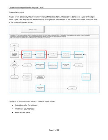
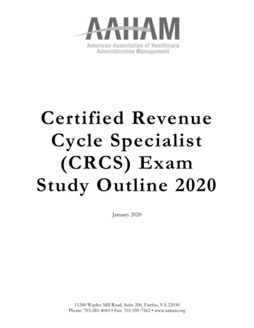
Fig. 2. Schematic of modules: f: fan section, ag: low pressure compressor, bg: high pressure compressor,ndc: turbine, e: shaft, h: combustor (Source: Process Plant Machinery, 2 edition, Bloch & Soares, C. pub: Butterworth Heinemann, 1998)Figure 3 below shows a gas turbine cutaway with its basic operating specification. Note this particular turbine model can be used forboth 50 and 60Hz power generation.Fig. 3. Alstom’s GT-8C2, 50/60Hz gas turbine with basic specification(Table 1: base load at ISO conditions) (Source: Alstom Power)Table 1. GT8C2 (60Hz) (ISO 2314: 1989)FuelNatural GasFrequency60 HzGross electrical output56.2 MWGross electrical efficiency33.8%Gross Heat Rate10,098 Btu / kWhTurbine speed6204 rpmCompressor pressure ratio17.6:1Exhaust gas flow197 kg/sExhaust gas temperature508 CNOx emissions, gas dry (corr. to 15% O2, dry) 25 vppm2
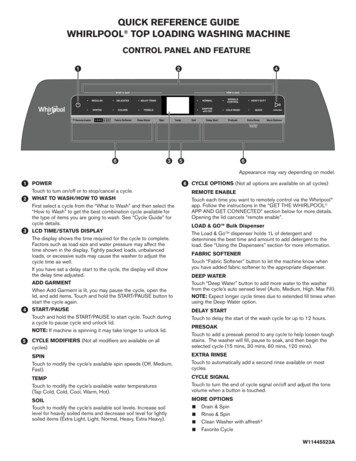
Claire SoaresFigure 4 shows another cutaway of another gas turbine. This gas turbine is used in 60Hz power generation service.Fig. 4. Siemens V84.3A, 60Hz gas turbine. Note partial hybrid burner (24 burners) ringFig. 5. The basic gas turbine cycle(Source: The Aircraft Engine Book, Rolls Royce UK)The basic gas turbine cycle is illustrated (PV and T-s diagrams) in Figure 5. A comparison can be drawn between the gas turbine’soperating principle and a car engine’s. See Figures 5 and 6. A car operates with a piston engine (reciprocating motion) and typicallyhandles much smaller volumes than a conventional gas turbine.3
1.1 Gas Turbines in Simple Cycle and Combined Cycle ApplicationsFig. 6. Comparison of the gas turbine and the reciprocating engine cycles (Source: The Aircraft Engine Book, Rolls Royce UK)GT Applications (Simple Cycle)Direct drive and mechanical driveWith land-based industries, gas turbines can be used in either direct drive or mechanical drive application. With power generation, thegas turbine shaft is coupled to the generator shaft, either directly or via a gearbox “direct drive” application. A gearbox is necessary inapplications where the manufacturer offers the package for both 60 and 50 cycle (Hertz, Hz) applications. The gear box will useroughly 2 percent of the power developed by the turbine in these cases.Fig. 7. A simple cycle gas turbine plant,100 MW simple cycle power plant,Charleston, South Carolina USA, poweredby Siemens gas turbines. (Source: Siemens Westinghouse)Power generation applications extend to offshore platform use. Minimizing weight is a major consideration for this service and the gasturbines used are generally “aeroderivatives” (derived from lighter gas turbines developed for aircraft use).For mechanical drive applications, the turbine module arrangement is different. In these cases, the combination of compressor module,combustor module and turbine module is termed the gas generator. Beyond the turbine end of the gas generator is a freely rotatingturbine. It may be one or more stages. It is not mechanically connected to the gas generator, but instead is mechanically coupled,4
Claire Soaressometimes via a gearbox, to the equipment it is driving. Compressors and pumps are among the potential “driven” turbomachineryitems. See Figure 8 below.Fig. 8. A typical free power turbine. (Source: Rolls-Royce, UK)In power generation applications, a gas turbine’s power/ size is measured by the power it develops in a generator (units watts,kilowatts, Megawatts). In mechanical drive applications, the gas turbine’s power is measured in horsepower (HP), which is essentiallythe torque developed multiplied by the turbine’s rotational speed.In aircraft engine applications, if the turbine is driving a rotor (helicopter) or propeller (turboprop aircraft) then its power is measuredin horsepower. This means that the torque transmission from the gas turbine shaft is, in principle, a variation of mechanical driveapplication. If an aircraft gas turbine engines operates in turbothrust or ramjet mode, (i.e. the gas turbine expels its exhaust gases andthe thrust of that expulsion, propels the aircraft forward), its power is measured in pounds of thrust. See Figure 9 below.Fig. 9. Propulsive efficiency is high for a propeller and low for a jet. (Source: Rolls-Royce, UK)5
1.1 Gas Turbines in Simple Cycle and Combined Cycle ApplicationsFig. 10. Gas turbines in offshore service: Offshore platformsproduce their own power. Power plant selection is generally anaeroderivative (for weight considerations) gas turbine in simplecycle operation. (Source: GE Power Systems)In marine applications, the gas turbine is generally driving the ship’s or ferry’s propellers, via a gear box.Fig. 11. Gas turbines in marine service: SGT-500 Industrial Gas Turbine – 17 MW,Application: Two SGT-500 power packages for FPSO vessel in the Leadon oilfields(Note the SGT-500 was Alstom’s, formerly ABB’s GT-35, designation changed afterSiemens acquisition). The Global Producer III from the Swan Hunter shipyards atTyneside, UK, heads for the Leadon oil field in the UK Sector of the North Sea. Thisvessel is an FPSO (Floating Production, Storage and Offloading) vessel, and poweron board is provided by two SGT-500 gas turbines. One WHRG (Waste Heat RecoveryGenerator) for each gas turbine heats process water. The SGT-500 is a light-weight,high-efficiency, heavy-duty industrial gas turbine. Its special design features are highreliability and fuel flexibility. It is also designed for single lift, which makes the unitsuitable for all offshore applications. The modular, compact design of the GT35Cfacilitates onsite modular exchange. (Source: Siemens Westinghouse)6
Claire SoaresGT24/26GT11N2Fig. 12a. Pictorial Examples of gas turbines, some with main operational parameters (Source: Alstom)Table 2. Alstom’s GT 24/ GT 26 (188MW 60Hz, 281MW 50Hz). Bothused in simple cycle, combined cycle and other co-generation applications.GT24 (ISO 2314:1989)FuelFrequencyGross Electrical outputGross Electrical efficiencyGross Heat rateTurbine speedCompressor pressure ratioExhaust gas flowExhaust gas temperatureNOx emissions (corr. to 15% O2,dry)Natural gas60 Hz187.7 MW*36.9 %9251 Btu/kWh3600 rpm32:1445 kg/s612 C 25 vppmGT26 (ISO 2314:1989)FuelFrequencyGross Electrical outputGross Electrical efficiencyGross Heat rateTurbine speedCompressor pressure ratioExhaust gas flowExhaust gas temperatureNOx emissions (corr. to 15% O2, dry)Natural gas50 Hz281 MW*38.3 %8910 Btu/kWh3000 rpm32:1632 kg/s615 C 25 vppmIn combined cycle, approximately 12 MW (GT26) or 10 MW (GT24) is indirectly produced by the steam turbine through the heat released in the gasturbine cooling air coolers into the water steam cycle.7
1.1 Gas Turbines in Simple Cycle and Combined Cycle ApplicationsTable 3. Alstom’s GT 11N2, either 60Hz or 50 Hz (with a gear box).Used in simple cycle, combined cycle and other cogeneration applications.GT11N2 (50Hz)FuelFrequencyGross Electrical outputGross Electrical efficiencyGross Heat rateTurbine speedCompressor pressure ratioExhaust gas flowExhaust gas temperatureNOx emissions (corr. to 15% O2,dry)FuelFrequencyGross Electrical outputGross Electrical efficiencyGross Heat rateTurbine speedCompressor pressure ratioExhaust gas flowExhaust gas temperatureNOx emissions (corr. to 15% O2,dry)Natural Gas50 Hz113.6 MW33.1%10,305 Btu/kWh3600 rpm15.5:1399 kg/s531 C 25 vppmGT11N2 (60Hz)Natural gas60 Hz115.4 MW33.6%10,150 Btu/kWh3600 rpm15.5 : 1399 kg/s531 C 25 vppmFig. 12b. SGT-600 Industrial Gas Turbine - 25 MW (former designation, Alstom’s GT10) (Source: Siemens Westinghouse)Technical SpecificationsDual Fuelnatural gas and liquidFrequency50/60 HzElectrical output24.8 MWElectrical efficiency34.2%Heat rate10,535 kJ/kWhTurbine speed7,700 rpmCompressor pressure ratio14.0:1Exhaust gas flow80.4 kg/sExhaust gas temperatureNOx emissions (corr. to 15% O2, dry)543 deg C 25 vppmFigures 13 and 14 depict a cutaway and an external view respectively, of two aeroderivative engine models.8
Claire SoaresFig. 13. The GE LM6000 (aeroderivative of the CF6-80C2). (Source: GE Power Systems)Fig. 14. The GE LM2500 (aeroderivative of the CF6-80C2). (Source: GE Power Systems)9
1.1 Gas Turbines in Simple Cycle and Combined Cycle ApplicationsFigure 15 shows an industrial gas turbine during assembly at the OEM’s facility.Fig. 15. GE-9H gas turbine is prepared for testing (Source: GE Power Systems)Fig.16. A GE Frame 9H during test/manufacture. (Source: GE Power Systems)Figure 17 shows an industrial gas turbine on a trestle in preparation for shipping.10
Claire SoaresFig. 17. A GE Frame 9F ready for shipping. (Source: GE Power Systems)Figure 18 shows a large GE Frame 7F industrial gas turbine on a test bed in the OEM’s facility.Fig.18. GE Frame 7F during manufacture/test showing rotor in half the casing (Source: GE Power Systems)Applications versatility of the gas turbineThe gas turbine’s operational mode gives it unique size adaptation potential. The largest gas turbines today are over 200 MW(megawatts) which then places gas turbines in an applications category that until recently, only steam turbines had owned.The smallest gas turbines are microturbines. The smallest commercially available microturbines are frequently used in small powergeneration (distributed power) applications and can be as small as 50 kW (kilowatts). Work continues on developing microturbinesthat will be thumbnail size. The world of “personal turbines” where one might plug this turbine into a “drive slot” in their car, comehome from work and plug it into a “household slot” for all one’s household power, is a discernable, if as yet unpredictable, target.The content on this CD deals mainly with power generation, however with the gas turbine, understanding its origins and otherapplications, gives the gas turbine community a better handle on optimized design, operation and maintenance. Gas turbines came into11
1.1 Gas Turbines in Simple Cycle and Combined Cycle Applicationstheir own in the Second World War In peacetime; NASA took over the research that led to better alloys, components, and designtechniques. This technology was then handed down to military aviation, and eventually commercial aviation. However, since the samemanufacturers also make gas turbines for land and marine use, aeroderivative gas turbines were a natural offshoot of their flyingforerunners.However, the same manufacturers also make gas turbines for land and marine use. So aeroderivative gas turbines were a naturaloffshoot of their flying forerunners.Aeroderivative gas turbines are essentially aviation gas turbines that are installed on a light frame and installed on a flat surface(ground based, marine craft or offshore platform). Aeroderivatives are commonly used in power generation service, particularly wherea relatively light package is required, such as in offshore service.The Rolls Royce Spey and Olympus engines for instance, are both aero engines but are also popular when packaged as aeroderivativesin land based and offshore platform service.Pratt and Whitney’s (PW) JT- 8D was once the largest (in terms of fleet size) aircraft engine family in existence. The engine firstmade its appearance in the 1950s and delivered about 10,000 pounds of thrust, then. Several variations on the basic core produced aversion that delivered roughly 20,000 pounds of thrust about twenty years later. This incremental power development around the samebasic design is common and saves on development costs, spares stocking costs and maintenance. PW’s FT- 8D is their aeroderivativeequivalent used in both power generation and mechanical drive application.Similarly General Electric’s (GE’s) LM2500 and LM6000 family (aero derivative) are essentially CF6-80C2 (aero) engines that havebeen adapted for land based use. What was ABB’s GT35 (land based), then Alstom’s GT35 (change of corporate ownership), thenSiemens Westinghouse’s SGT500 (yet another corporate purchase) is another example of an aeroderivative. Most aeroderivatives canalso be used in marine (ferry, ship) applications. Some of them are also used on mobile land applications, such as in military tanks.Aero and aeroderivative gas turbine engines are likely to be built in modular construction. This means that one module of the gasturbine engine may be removed from service and the other modules left in place. A substitute module may be inserted in place of theremoved module so the gas turbine can resume service. An industrial engine is more likely to be constructed in a non-modular format.If part of an industrial engine has serious problems, it is likely that the entire engine will be “down for maintenance”.The term “industrial” gas turbine implies a heavier frame and a gas turbine model that was not intended for service where the mass(weight) to power ratio (in other words weight minimization for the power plant) was of paramount concern. That said, themetallurgical selections for contemporary industrials reflect the best developments in metallurgical selections. The gas turbine field isa highly competitive one, and the highest turbine inlet temperatures (TITs) that can be tolerated by the metallurgical and fuelselections, are sought as this optimizes the gas turbine’s peak power rating. In other words, GE’s industrial Frame 7s and 9s (be they“- F”, “- G” or “- H” technology) may incorporate similar metallurgy to that used on their aircraft engines. The letters F, G and H referto temperature ceilings and therefore imply higher power (with “later” alphabet letters).Some turbine model designations can appear confusing due to several changes in corporate ownership. This is partly due to the factthat the OEM (original equipment manufacturer) gas turbine scene changes constantly with corporate mergers, partial mergers,buyouts of specific divisions and joint ventures. This section and the one on combined cycles therefore have several notes aboutspecific engines’ model designation history and previous ownership. This has considerable relevance when it comes to noting the finerpoints of any gas turbine’s design. This is critical to operators as they can then make better decisions regarding the overhaul,performance optimization, component updates and retrofit systems on their turbine systems.Any application of a gas turbine could have a great deal to offer end-users in other industrial sectors. Power generation is often theleast demanding application for a given gas turbine, unless it used in variable load/ peaking service. Mechanical drive units are morelikely to experience load swings. One example would be turbines driving pumps that injects (into the soil) varying volumes of seawater that accompany “mixed field” (oil, gas and seawater deposits) oil and gas production.Aircraft engine turbines may see varying stresses depending on their service. If for instance, one considers an aerobatic squadron, oneneeds to be aware that the engines on the planes trying to stay a fixed distance from the wing tip of the formation’s leader mayaccumulate life cycle losses of twenty times that of the formation leader’s engines.In other words, the variations in all parameters that pertain to a gas turbine’s overall life, component lives or time between overhauls(TBOs) offer insight to gas turbine operators regardless of whether that turbine operates in “their” industry or not. Lessons which are12
Claire Soareslearned in one sector of industry on gas turbine metallurgy and operating systems, such as controls or condition monitoring, can beapplied in some way, to other gas turbine applications.The History of the Gas TurbineThe development of the gas turbine took place in several countries. Several different schools of thought and contributory designs ledup to Frank Whittle’s 1941 gas turbine flight. Despite the fact that NASA’s development budget now trickles down to feed theimprovement of flight, land based and marine engines, the world’s first jet engine owed much to early private aircraft engine pioneersand some lower profile land-based developments.The development of the gas turbine is a source of great pride to many engineers world wide and, in some cases takes on either industrysector fervor (for instance the aviation versus land based groups) or claims that are tinged with pride with one’s national roots. Peoplefrom these various sectors and subsectors can therefore get selective in their reporting.So for understanding the history of the gas turbine, one would have to read several different papers and select material written bypersonnel from the aviation, and land-based sectors. At that point, one can “fill in the gaps”.What follows therefore are two different accounts of the gas turbine’s development. Neither of them is wrong. The first of thesepresents an aircraft engine development perspective. ** Reference: “The History of Aircraft Gas Turbine Development in the United States”, St. Peter, J., Published IGTI, ASME, 1999.Attempts to develop gas turbines were first undertaken in the early 1900’s, with pioneering work done in Germany. The mostsuccessful early gas turbines were built by Holzwarth, who developed a series of models between 1908 and 1933. The first industrialapplication of a gas turbine was installed in a steel works in Hamborn, Germany, in 1933. In 1939 a gas turbine was installed in apower plant in Neuchâtel.1931 U.S. army awards GE a turbine-powered turbosupercharger development contract1935 U.S. Army, Northrop, TWA, and GE combine to test fly a Northrop Gamma at 37,000 feet from Kansas City to Dayton. This ledto a production contract for GE to build 230 units of the “Type B” supercharger and led to establishment of the GE SuperchargerDepartment in Lynn, Massachusetts (later the site of the I-A development based on the Whittle engine).1938 Wright Aeronautical Corporation designs its own vaned superchargers for its own engines, although the superchargers weremanufactured for Wright by GE.1940 NACA joins with Wright, Allison and P&W to standardize turbo supercharger testing techniques.1.1 Simple and Combined Cycles1925 R.E. Lasley of Allis-Chalmers receives the first of several patents on gas turbines.Around 1930 he forms the Lasley Turbine Motor Company in Waukegan, IL. with the goal of producing a gas turbine for aircraftpropulsion.1934 U.S. Army personnel from Wright Field visit Lasley’s shop and inspected his hardware and the engine which he had filmed inoperation earlier that year. However, neither the Army nor Navy would fund Lasley.1939 GE studies gas turbine aircraft propulsion options and concludes the turbojet is preferable to the turboprop. Note, however, thattwo years later they changed their minds and proposed a turboprop to the Durand Committee.1941 GE Steam Turbine Division (Schenectady) participates in the Durand Special Committee on Jet Propulsion and proposes aturboprop, designated the TG-100 (later the T31), which ran successfully in May 1943 under Army sponsorship.1941 GE Turbo Supercharger Division (Lynn, Massachusetts) receives the Whittle W.1.X engine and drawings for the W.2.Bimproved version. A top secret effort begins to build an improved version, known as the I-A, for flight test in the Bell P-59.1941 Durand Committee also awards Navy contracts to Allis-Chalmers and Westinghouse. The Westinghouse W19, a small boosterturbojet, resulted from this but Allis-Chalmers dropped out of the “gas turbine race” in 1943.13
1.1 Gas Turbines in Simple Cycle and Combined Cycle Applications1942 In April, the GE I-A runs for the first time in a Lynn test cell. In October, it powers the Bell P-59 on its first flight at Muroc DryLake, CA.1929 Haynes Stellite develops Hastelloy alloy for turbine buckets, allowing operation up to gas temperatures of over 1800 F. Thissuperior alloy was later crucial to the successful operation of the I-A and it gave U.S. turbine manufacturers the ability to use uncooleddesigns rather than include the complexity of blade cooling.By the latter part of 1942, the following “native” aircraft gas turbine efforts were proceeding. These projects included:1. Northrop Turbodyne turboprop2 .P&W PT-1 turboprop3. GE/Schenectady TG-100 turboprop4. Allis-Chalmers turbine-driven ducted fan5. NACA piston-driven ducted fan6. Westinghouse 19A turbojets7. Turbo Engineering Corporation’s booster-sized turbojetThe following timeline contains many of the relevant land based gas turbine design developments. *Note that this also contains some timeline references to aircraft engine development.* Reference: ASME 2001 - GT- 0395 “Advanced gas turbine technology – ABB/ BBC historical firsts” by Eckardt, D., and Rufli,P., ALSTOM Power Ltd.Note: BBC Brown Boveri Company, ABB Asea Brown BoveriSwitzerland (& Swiss Abroad)1921 J. Ackeret, high-speed aerodynamics scientist at ETH Zurich, arrives at L. Prandtl’s AVA Aerodynamische Versuchs-AnstaltGottingen; stays seven years1925 CEM (G. Darrieus) - a French subsidiary of BBC (Brown Boveri Company) produces a series of windmills, using airfoil designtheory.1926 BBC’s 4 stage axial test compressor designed, first with untwisted blades, later swirl adapted.1932 BBC sold a number of 11 stage axial compressors, PR 3.4, for the Mondeville project and high-speed windtunnels at ETHZurich and Rome.1934 C. Keller, assistant to J. Ackeret at ETH Zurich, designed one of the windtunnel blowers (2nd blower for high speed tunnel camefrom BBC).1939 A. Meyer, BBC’s Technical Director, presents a comprehensive paper on GT design achievements (including GT usage forcompact & lightweight ship/destroyer propulsion) at the Institute of Mechanical Engineering, London First commercial industrial GT from BBC is operational at Neuchatel BBC delivers 1st Industrial GT to RAE, 1.6 MW 20 stage axial compressor In 1940 BBC delivers axial aircraft superchargers, 190 hp, PR 2.5 to complete a RR purchase orderGermany (& Germans Abroad)1922 W. Bauersfeld suggests the use of airfoil theory for fluid machinery1935 At AVA Gottingen, a 4 stage axial turbocharger, 7 stage compressor design undergoes development (Encke et al. design),PR 3.8 [in production PR 3.1].1935 H.P. von Ohain gets a secret turbo-engine patent no.317/381937 H.P. von Ohain’s test engine HeS313 runs1939 The first jet-powered flight He 178 aircraft with HeS313, on Sunday Aug 27, 1939.14
Claire Soares R. Friedrich, Junkers Magdeburg, design the 14 st. axial compressor for the “RTO” engine (Riickstoss-Turbine ohneLeistungsabgabe with a Propeller), for the Helium aircraft S30 engine, based on Gottingen airfoil design1942 Me 262 fighter aircraft entered service with two Jumo 004 engines, first test flight on August 18.England (& English Abroad)1926 A.A. Griffith releases “An Aerodynamic Theory of Turbine Design”, which discusses a GT as an aircraft’s power plant1930 F. Whittle gets the first patent for a turbo aeroengine Tizard, Gibson & Glauert committee denies that the gas turbine could be superior to the piston engine1937 F. Whittle, radial compr. engine, test run on December 41938 A delegation at BBC decides that “Exclusivity on the BBC (axial) compressor design would not be granted”1941 The Whittle engine has its first flightNote that in the early 1930s, BBC designed components used for the Velox project boilers. They developed a turbine that had enoughpower to drive the compressor, and could also generate excess power through the inverse operation of the electric starter motor. Also,in 1936, BBC’s '34MW all-axial process gas turbine/ blower train with a PR 4, was supplied to a US refinery.In July 1939, BBC commissioned the world’s first utility gas turbine at Neuchatel, Switzerland. The gas turbine had one 23 stage axialcompressor, one single-can combustor, one 7 stage axial turbine, and a synchronously operated generator on the same shaft.Fig. 19. BBC - First Utility GT Power Plant, 4 MW, Neuchatel, Switzerland, 1939 (courtesy Alstom Power)15
1.1 Gas Turbines in Simple Cycle and Combined Cycle ApplicationsGas Turbine Major Components, Modules, and Basic SystemsFig. 20. Modules in a gas turbine Source: Courtesy of ButterworthndHeinemann, from “Process Plant Machinery” 2 edition, Bloch, H.and Soares, C., 1998, original source Rolls Royce UKPrimary ModulesThe primary modules in a gas turbine are the: Compressor module Combustion module Turbine moduleA gas turbine also has an inlet section/ module and an exhaust section/ module. See Figure 20.Most advanced and large gas turbines have compressors that are the axial design type. Some of the earlier, smaller or deliberatelycompact gas turbines have centrifugal compressors. See Figures 21, 22, 23.Each compressor stage provides an opportunity for stepping up the overall compressor pressure ratio (PR), so although an axial stagemay not offer as much of a PR as a centrifugal stage of the same diameter, a multistage axial compressor offers far higher PR (andtherefore mass flow rates and resultant power) than a centrifugal design.16
Claire SoaresFig. 21. Centrifugal-compressor flow, pressure, and velocity changes(a) Airflow through a typical centrifugal compressor,(b) Pressure and velocity changes through a centrifugal compressor.Courtesy Rolls Royce UKFig. 22. A modern high-performance compressor assembly.(General Electric) (Source: “Aircraft Gas Turbine Engine Technology” McGraw Hill)17
1.1 Gas Turbines in Simple Cycle and Combined Cycle ApplicationsFig. 23. Stator case for the General Electric 179 engine.(Source: “Aircraft Gas Turbine Engine Technology” McGraw Hill)Therefore most gas turbine designs incorporate axial compressors. In newer designs, the compressor and turbine modules may be splitinto further submodules, to lessen the stress on individual components and achieve better efficiencies.So a compressor may have a low pressure (LP) module or LPC, and a high pressure module (HPC). In this case there will beequivalent high and low pressure turbine modules (LPT and HPT). The LPC and LPT will operate on one long shaft at the samespeed. The HPC and HPT will operate on a shorter shaft that fits around and concentric to, the low pressure shaft, and at a higherspeed than the low pressure module. See Figure 21.Some contemporary gas turbines have three modules, designated low, intermediate and high pressure, each with their own shaft.This modular concept allows for module replacement or exchange, if maintenance to a module is required, without taking the entiregas turbine out of service.Module component aerodynamic and thermodynamic basicsAir inlet sectionA gas turbine takes in many multiples of what an equivalent size reciprocating engine can. The air inlet is generally a smooth, bellshaped, aluminum alloy duct. It leads air into the compressor with minimized turbulence. Typically, struts brace the outer shell of thefront frame to minimize air flow vibration.An anti-icing system directs compressor air (at discharge or some pressure higher than atmospheric) that is bled off an appropriatecompressor stage, into these struts. The temperature of this air prevents ice formation. Ice ingestion can and has destroyed many gasturbine engines.Compressor moduleThe compressor is made up of rotating blades on discs and stationary vanes that direct the air to the next row of blades. The first stagecompressor rotor blades accelerate the air towards their trailing edges and towards the first stage vanes. The first stage vanes slow theair down and direct it towards the second stage compressor rotor blades, and so on through the compressor rotor stages (each stage isone rotating stage and one stationary stage).18
Claire SoaresThen air enters the diffuser section. The highest total air velocity and maximu
Fig. 5. The basic gas turbine cycle (Source: The Aircraft Engine Book, Rolls Royce UK) The basic gas turbine cycle is illustrated (PV and T-s diagrams) in Figure 5. A comparison can be drawn between the gas turbine’s ope