Transcription
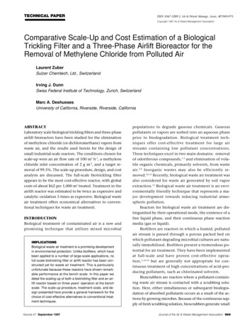
Zuber,and DeshussesISSN 1047-3289J. Air &Dunn,Waste Manage.Assoc. 47:969-975TECHNICAL PAPERCopyright 1997 Air & Waste Management AssociationComparative Scale-Up and Cost Estimation of a BiologicalTrickling Filter and a Three-Phase Airlift Bioreactor for theRemoval of Methylene Chloride from Polluted AirLaurent ZuberSulzer Chemtech, Ltd., SwitzerlandIrving J. DunnSwiss Federal Institute of Technology, Zurich, SwitzerlandMarc A. DeshussesUniversity of California, Riverside, Riverside, CaliforniaABSTRACTLaboratory scale biological trickling filters and three-phaseairlift bioreactors have been studied for the eliminationof methylene chloride (or dichloromethane) vapors fromwaste air, and the results used herein for the design ofsmall industrial-scale reactors. The conditions chosen forscale-up were an air flow rate of 100 m3 h-1, a methylenechloride inlet concentration of 2 g m-3, and a target removal of 99.5%. The scale-up procedure, design, and costanalysis are discussed. The full-scale biotrickling filterappears to be the most cost-effective reactor, with globalcosts of about 62 per 1,000 m3 treated. Treatment in theairlift reactor was estimated to be twice as expensive andcatalytic oxidation 5 times as expensive. Biological wasteair treatment offers economical alternatives to conventional techniques for waste air treatment.INTRODUCTIONBiological treatment of contaminated air is a new andpromising technique that utilizes mixed microbialIMPLICATIONSBiological waste air treatment is a promising developmentin environmental protection. Unlike biofilters, which havebeen applied to a number of large-scale applications, nofull-scale biotrickling filter or airlift reactor has been constructed yet for waste air treatment. This is particularlyunfortunate because these reactors have shown remarkable performance at the bench scale. In this paper wedetail the scaling-up of both a biotrickling filter and an airlift reactor based on three years’ operation at the benchscale. The scale-up procedure, treatment costs, and design presented here provide a general framework for thechoice of cost-effective alternatives to conventional treatment techniques.Volume 47 September 1997populations to degrade gaseous chemicals. Gaseouspollutants or vapors are sorbed into an aqueous phaseprior to biodegradation. Biological treatment techniques offer cost-effective treatment for large airstreams containing low pollutant concentrations.These techniques excel in two main domains: removalof odoriferous compounds,1-3 and elimination of volatile organic chemicals, primarily solvents, from wasteair. 3-9 Inorganic wastes may also be efficiently removed.10-12 Recently, biological waste air treatment wasalso considered for waste air generated by soil vaporextraction.13 Biological waste air treatment is an environmentally friendly technique that represents a major development towards reducing industrial atmospheric pollution.Reactors for biological waste air treatment are distinguished by their operational mode, the existence of afree liquid phase, and their continuous phase reactionmedia (gas or liquid).Biofilters are reactors in which a humid, pollutedair stream is passed through a porous packed bed onwhich pollutant-degrading microbial cultures are naturally immobilized. Biofilters present a tremendous potential for air treatment. They have been implementedat full-scale and have proven cost-effective operation, 3,14-16 but are generally not appropriate for continuous treatment of high concentrations of acid-producing pollutants, such as chlorinated solvents.Bioscrubbers are reactors where a pollutant-containing waste air stream is contacted with a scrubbing solution. Here, either simultaneous or subsequent biodegradation of absorbed pollutants occurs as a result of the actions by growing microbes. Because of the continuous supply of fresh scrubbing solution, bioscrubbers generate smallJournal of the Air & Waste Management Association 969
Zuber, Dunn, and Deshussesamounts of wastewater that can be easily treated.Bioscrubbers offer promise for the elimination of suchacid-producing pollutants as chlorinated VOCs, including dichloromethane (DCM or methylene chloride),trichloroethylene (TCE), and perchloroethylene(PCE),17-20 or such inorganics as H 2S.10,12 Bioscrubbershave yet to be implemented for industrial use, primarily due to higher costs and complexity, and cloggingby biomass growth. 21,22 Among the various types ofbioscrubbers, biotrickling filters and three-phase airlift reactors are the most promising equipment. 7,20,23Airlift reactors are extensively used for wastewatertreatment, and have recently been shown highly effective for waste air treatment.20,25 Although more complex and more expensive than biofilters, bioscrubbershave proven superior in eliminating acid-producingpollutants, such as chlorinated VOCs. One reason forthis is that in bioscrubbers, pH control and removal ofmetabolites are easier to achieve because of the existence of a free liquid phase. Also, nutrients are continuously supplied and, in the presence of net biomass growth, higher pollutant degradation rates are obtained. Unlike biofilters, which have been applied to anumber of large-scale applications,14,16 biotrickling filters or airlift reactors have been rarely scaled-up forindustrial waste air treatment. This is particularly regrettable because these reactors have shown remarkable performance at the bench scale. 18,20,24 In this paper, we describe the scale-up of a biotrickling filter andt hre e- pha se a i rl i ft rea ct o r fo r t rea t m ent o fdichloromethane-contaminated air. The design is basedon three years of highly effective operation of benchscale units. Cost estimation is provided and comparedto conventional treatment techniques. The reactor designs described herein are versatile and apply equallyto the treatment of other pollutant vapors.SCALE-UP OF THE BIOREACTORSThe conditions considered for the full-scale biotricklingfilter are described in Table 1. These conditions are representative of a small, but concentrated, industrial exhaustair flow rate.Table 1. Conditions for scale-up.Waste air flow rate*:Pollutant:Pollutant inlet concentration:Removal targeted:Outlet DCM concentration:*100 m3 h-1CH2Cl2 (methylene chloride or dichloromethane)2 g m-3 ( 530 ppmv)99.5% 0.01 g m-3Higher air flow rates (e.g., 300 m3 h-1) and lower DCM inlet concentrations could betreated with similar removal percentages.970 Journal of the Air & Waste Management AssociationScale-Up Common to Both ReactorsBiodegradation of 99.5% of 200 g DCM h-1 corresponds to2.34 mol h-1 and results in the generation of 4.69 mol h-1 ofHCl. This means 187 g h-1 of NaOH pellets to maintain thepH constant or, if a 30% solution (8.7 103 mol m-3) is used,a flow of 0.54 10-3 m3 h-1. A corresponding tank volume of0.79 m3 is necessary if the solution is prepared every twomonths. The composition of the scrubbing solution wasnot optimized at the bench scale, but was designed sothat the process culture will not be limited by mineralsalts. To calculate salt consumption costs, the amounts usedat the bench scale were multiplied by the scale-up factor,with the following results: ammonium sulfate, 23.0 g h-1;potassium dihydrogen phosphate, 9.2 g h-1; magnesiumsulfate heptahydrate, 8.4 g h-1; and calcium nitratetetrahydrate, 3.4 g h-1.The combination in an aqueous solution of the phosphate anions with the magnesium and calcium cationsmay precipitate owing to their low solubility. It is therefore an advantage to store and provide those minerals ina solid form. Since 1 kg of salt in powder form occupiesabout 1 L, a tank to contain the total amount needed fortwo months should have a volume of 65 L. This type ofstorage also has the advantage of avoiding the formationof algae in the tank. Different authors report the use ofadditional trace elements in the scrubbing solution.20,21,25The amounts, however, are about 1,000 times smaller thanthe above-mentioned salts and are neglected in this discussion.The variables that need to be controlled are pH, conductivity, and temperature. It may also be useful to monitor dissolved oxygen to avoid oxygen limitation. The pHcontrol allows the degradation rate to be calculated20 andcan therefore be used to control the addition of the saltneeded by the biomass. The conductivity measurementshould be used for the control of the liquid residence timewith a fresh water flow to avoid an inhibition by the chloride concentration.20,21,25 The temperature is kept at 30 Cwith a steam flow. The energy balances are establishedwith the values listed in Table 2. In both cases, the reactors are supposed to be thermally perfectly insulated.For energy balances, the air flow entering the reactors is assumed to be at ambient temperature and dry, butthe calculation can easily be modified for hot and/or humid air streams. The reaction heat is negligible and isTable 2. Values for the establishment of the energy balances.26Heat capacity of dry air:Heat capacity of water:Water vaporization energy (30 C):Steam condensation energy (3 bar):1.3 103 J kg-1 K-14.18 103 J kg-1 K-12.28 106 J kg-12.16 106 J kg-1Volume 47 September 1997
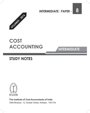
Zuber, Dunn, and DeshussesFigure 1. Schematic of a full-scale-up trickling filter for the conditionslisted in Table 1.omitted in the following calculations. The air can be considered to be saturated with water vapor at the outlet; thus, heat isneeded to compensate the vaporization energy. The absolutehumidity saturation of air at 30 C is 0.028 kg m-3. Thus,1.77 kW are needed to provide the heat of vaporizationto saturate the dry air flow.Scale-Up of the Biotrickling FilterThe scale-up of the biotrickling filter is based on the standard experimental operating conditions of the bench-scalereactor.20 The column diameter is calculated by assumingthe same empty-tube superficial gas velocity (160 m h-1).The packing (Sulzer Mellapak 350Y) is the same as studiedat the bench scale. It is a stainless steel structured packingthat provides a large surface for gas/liquid absorption andfor biofilm formation, and a high void volume so that clogging problems caused by biomass growth can be significantly reduced.20 In the full-scale reactor, it is divided intotwo sections to ensure proper pH control and homogeneouswetting. With only one large section, liquid channelingcould not be excluded. Also, the two-section design allowsone section to be cleaned while the other is still removingDCM. In doing so, major impact on the environment during maintenance can be prevented because 92% of the DCMis removed in the first section and the remaining 7.5% inthe second section. A relaxation modeling approach20showed that two sections of 2.4 m height are necessary toachieve 99.5% removal under the conditions considered.It should be noted that under these conditions, the DCM isessentially biodegraded and that the amount of DCM leaving with the liquid purge is virtually zero. For the conditions chosen, the diameter of the biotrickling filter equals0.89 m (cross-section area of 0.625 m2). The total of 3 m3packing volume provides about 1,050 m2 of surface area forbiofilm formation.Volume 47 September 1997Gas flows downward co-currently with the liquidthrough the packing. As verified experimentally, the trickling filter does not produce any significant pressure dropover extended operating time, and therefore no specialcompressor is required.The liquid circulates in two loops, wetting the twosections of the packing. On the basis of the performanceobtained at different liquid velocities,20 11 m h-1 is appropriate and implies a liquid flow of 6.88 m3 h-1 in eachloop. For the choice of the recirculation pump, the headpressure in the recycling loop should not exceed 0.5 bar.The dynamic liquid hold-up has been evaluated at 0.09 m3of liquid per m3 of reactor,20 or 0.14 m3 for each section. Inthe upper loop, a small tank (0.05 m3) retains water forthe different controls (see Figure 1), whereas in the lowerloop, the bottom of the column is used for this purpose.A total volume of approximately 0.2 m3 of liquid is obtained for each loop. For an average hydraulic residencetime of 3 h, the two loops need a total fresh water flow of0.13 m3 h-1.The energy needed to maintain the system at constant temperature can be approximated as follows. Becausedry air has a heat capacity of 1,300 J kg-1 K-1, 0.4 kW areneeded to raise its temperature of 20 C to 30 C, and 1.8 kWare needed to heat the fresh water flow. Obviously, if the residence time of the liquid is increased, this energy needdecreases. The total heat energy needed by the reactor istherefore the sum of the water heating, the air heating,and the compensation of the evaporation. The result is4.0 kW, which can be brought to the reactor through theheat exchangers in the two liquid loops. A schematic ofthe industrial scale trickling filter is shown in Figure 1.Scale-Up of the Three-Phase Airlift BioreactorScaling-up a three-phase airlift reactor is a difficult task,as preferential liquid flows might lead to a partial fluidization of the carrier on which the process culture is immobilized. The scale-up calculations are based on the workof Heijnen et al.,27 who reported the successful operationof a 17 m high three-phase airlift reactor for wastewatertreatment, containing sand as a biomass carrier. Thedowncomer flow was obtained with a draft tube of 3.1 m,and the total diameter was 4.5 m. The correspondingdowncomer/riser cross-sectional area ratio therefore was111%. This is a reasonable value for high velocities in theriser, as reported by Weiland.28As for the biotrickling filter, the reactor diameter is calculated with the similarity in gas velocity between thebench and the full-scale airlift. For a gas velocity of 183m h-1 (empty basis), the diameter of the riser must havea cross-sectional area of 0.546 m2; thus, a diameter of0.83 m. To be comparable to the proportions of the reactor described by Heijnen et al.,27 the downcomer mustJournal of the Air & Waste Management Association 971
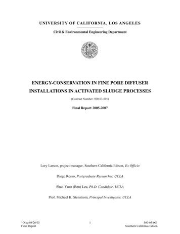
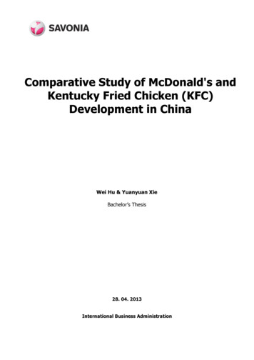
Zuber, Dunn, and DeshussesTable 3. Currency rates in May 1995 for 1 US . Inflation based on Chemical Engineering Plant Cost Index.30Currency Rates1.205 Swiss Franc:1.45 German Mark:1.62 Dutch Guilder:1988-1994 Inflation 4:358.2359.2368.1have a cross-sectional area of 0.606 m2, and the diameter ofthe outer tube becomes 1.2 m. Since our prototype airliftreactor was found to be controlled by this gas-liquid transfer of DCM up to a gaseous concentration of about 15 g m3, the reactor height corresponds to the length for whichthe required gas-liquid transfer is achieved. The full-scalereactor is designed with a larger downcomer area than theprototype to ensure optimum fluidization of the biocatalyst and should equal, if not surpass, the performance ofthe prototype. However, the process will still be controlledby gas-liquid transfer. A mathematical model assuming theairlift reactor to be similar to a bubble column did not allow the removal of DCM to be predicted with sufficientconfidence for the present scale-up.20 Therefore, a graphical method based on experimental results obtained withthe bench-scale airlift was used to predict the reactor heightneeded. As illustrated in Figure 2, for an inlet gaseous concentration of 2 g m-3, the outlet concentration of methylene chloride for the bench-scale reactor was 0.30 g m-3. Astagewise construction shows that three reactor heights aresufficient to reduce the DCM concentration to the required0.010 g m-3. Because the liquid height in the bench-scalereactor was 0.83 m, the total height for the full-scale plantshould be 2.5 m. Owing to the difficulty of the gassparging in the base, 0.5 m is added to ensure proper gasdistribution.The final height obtained for the riser is 3 m, which corresponds to a total riser volume of 1.6 m3, with a gas hold-up ofFigure 2. Experimental results of DCM removal in the airlift reactorand stagewise construction to determine the height needed to reachan outlet concentration of DCM of 0.01 g m-3 for an inlet concentrationof 2 g m-3. Gas velocity (empty basis) is 183 m h-1.972 Journal of the Air & Waste Management Association0.13 m3 (8%), and an outer ring volume of 1.8 m3. The totalreactor volume obtained is 3.4 m3. As for the prototype,sand (density 2.6 103 kg m-3) is used as a carrier for biomass. The proportions are kept the same (195 kg m-3) sothat the sand mass is 660 kg. The total volume of liquidfound by difference is 3 m3.The waste air must be pumped into the reactor. Thepressure required is about 0.5 bar: 0.3 bar for the watercolumn and about 0.2 bar for the sparger specially designed to avoid back-flowing. The turbulence of the airlift reactor was shown to produce important amounts offoam, possibly because of macro-molecules released bybiomass damaged by the shear forces. Anti-foam wasshown to increase gas bubble size and is therefore not appropriate. The foam can be destroyed with a rotating diskor with a high-pressure jet. This second option was successful for the reactor described by Heijnen et al.27 Foam destruction should be reached with a liquid jet of 0.1 m3 h-1 at10 bar.Regarding energy balances, the reactor must be keptat 30 C. The flow of energy has to take into account theheat produced by the compression of the air flow. Thereversible and adiabatic compression of air (bi-atomicmolecules) from atmospheric pressure to 0.5 barg wasapproximated as follows:29 P T2 T1 2 P1 0.286(1)where T is the temperature in K, and P is the pressure. Fora pressure increase of 0.5 bar and an initial temperatureof 20 C, the final temperature is 56 C. This can kill locally the biocatalyst and diminish the gas-liquid masstransfer. Consequently, a heat exchanger is designed, using the fresh water flow to decrease the polluted air streamFigure 3. Schematic of a full-scale airlift reactor for the conditionslisted in Table 1.Volume 47 September 1997
Zuber, Dunn, and DeshussesTable 4. Variable costs for a Swiss chemical industry in January 1995.31Tap water:Cooling water:Waste water (industrial):Electricity:Steam at 3 bar:Personnel:2.73 m-30.40 m-32.02 m-30.10 kWh-10.026 kg-160 h-1temperature to 30 C. The water flow needed to keep thehydraulic residence time at 3 h is 1 m3 h-1. The exchange of1.2 kW between the air and the water will raise the temperature of the water stream about 1 C. Assuming the watersupply is at 18 C, an additional energy flow of 13 kW is neededto reach the required temperature of 30 C. The total heatenergy needed by the reactor in this case is the sum of thewater heating and the compensation of the evaporation. Itamounts to 14 kW, and can be brought to the reactorthrough a coil around the reactor body.A schematic of the design of the industrial scale threephase airlift reactor considered here is shown in Figure 3.INVESTMENT AND TREATMENT COSTESTIMATIONSince cost estimations are based on different currencies, allcosts were converted to US , with the following rates andinflation values reported in Table 3.Only the main variables and fixed costs for both reactorsare estimated. Table 4 indicates the variable costs; Table 5,the costs of the mineral salts. It should be mentioned thatthe costs reported in these tables can differ as much as 1order of magnitude, depending on local rates, with significant consequences for the treatment costs. The values inTables 4 and 5 are probably at the high end.The cost estimations of pumps, heat exchanger, and powerrequirement were achieved with ASPEN (Version 8.5-6, 1990),Aspen Technology Inc., Massachusetts, USA). The tank priceswere obtained from Walas,32 except for the small tank containing the mineral salts, which was taken from the 1995 Semadenicatalogue (Semadeni AG, Bern, Switzerland).In the following section describing the total costs specific to the bioreactors, the variable costs are reported inUS per year. A year consists of 8,760 hours (100% operation).Biological Trickling FilterCosts for the biotrickling filter are summarized in Table 6.The cost listed in Table 6 is for an installation working on acontinuous basis for 10 years. The investment per hour ofoperation is therefore 2.10 h-1. Added to the operating costof 4.11 h-1, one obtains a total cost of 6.21 h-1. For a flowof 100 m3 h-1 containing 2 g m-3, the cost for a removal of99.5% in a trickling filter is 62 per 1,000 m3.Volume 47 September 1997Table 5. Costs of the mineral salts (technical grade) in a Swiss chemical industryin January 1995.31Sodium hydroxideAmmonium sulfatePotassium dihydrogen phosphateMagnesium sulfate heptahydrateCalcium nitrate tetrahydrate kg-1 kg-1 kg-1 kg-1 kg-10.958.5147.010Airlift BioreactorCosts for the airlift reactor are summarized in Table 7. The costlisted in Table 7 is for an installation working on a continuousbasis for 10 years. The investment per hour of operation istherefore 3.16 h-1. Added to the operating cost of 9.10 h-1,one obtains a general cost of 12.3 h-1. For a flow of100 m3 h -1 containing 2 g m-3, the cost for a removal of 99.5%in a three-phase airlift reactor is 123 per 1,000 m3.Economical ConsiderationsThe two estimations determined the following treatmentTable 6. Total cost calculation for the biotrickling filter. The costs of the column andthe packing were a personal communication by Sulzer AG, Switzerland.Description of the costInvestment[US ]Column (stainless steel)Packing Sulzer Mellapak 350YBlower for the air flowElectricity (250 W)2 pumps for the water circulation flowElectricity (330 W, twice)Tank in the upper loop (stainless steel)ChemicalsTank for the baseNaOH consumptionTank for the mineral nutrientsMineral consumption2 heat exchangers (stainless steel)Steam flow (4,000 W)72,00016,2005,500Subtotal of the basic investmentSecondary costControls (12% of the basic investment)Pipes (20% of the basic investment)Insulation (7% of the basic investment)Building (20% of the basic investment)Tap water (0.13 m3 h-1)Waste water (0.13 m3 h-1)Personnel (4 days per month or 384 h year-1)115,900Totals184,100Operatingcost[US rnal of the Air & Waste Management Association 973
Zuber, Dunn, and Deshussescosts for 1,000 m3 of waste air: biotrickling filter– 62 per1,000 m3, and airlift reactor– 123 per 1,000 m3.According to these calculations, the biotrickling filterappears to be about 50% cheaper than the airlift reactor.The comparison of the obtained costs with previously published values must be considered with care as chemical andenergy costs may vary greatly with local rates. Also, thereactor size and the outlet gas concentration consideredare generally different. Diks21 reported a cost of 4 per 1,000m3 for a trickling filter operating with 10,000 m3 h-1 of airand 85% removal of the 1 g m-3 inlet DCM concentration.For a trickling filter similar to the one reported in our study,a predicted cost of 8 per 1,000 m3 can be calculated fromJackman and Powell.33 A detailed design and requests forbids, as well as estimation of operating cost with local rates,would be necessary for an accurate figure of the overall treatment cost. Besides differences due to calculation methods,the above examples illustrate that specific costs significantlyincrease for smaller reactors, high inlet concentrations, andhigh removal percentages. Thus, cost effectiveness of biological waste air treatment becomes more interesting withlarge air streams.As seen in Tables 6 and 7, tap and waste water expenses represent a large fraction (20 to 50%) of the operating costs. Even if these numbers will most likely varyaccording to local rates (as much as 10 times lower thanlisted in Table 4), particular attention should be given tooptimize the water flow rate. For the airlift, the tap water flow can be reduced by decreasing the volume of thereactor by choosing a smaller downcomer/riser sectionratio. In both reactors, water can be saved by increasingthe hydraulic residence time until an inhibitory salt concentration is reached.The 62 and 123 for the treatment of 1,000 m3 ofpolluted air in the trickling filter and the airlift reactor,respectively, can be compared to the expenses associatedwith conventional treatment. Costs were obtained froma Swiss chemical industry using thermal combustion totreat 50 m3 h-1 of waste gas containing over 300 g m-3 ofchlorinated solvents. The advantage of thermal combustion is the almost total freedom it allows with respect tothe inlet concentration and the composition of the flowtreated (e.g., mixtures of pollutants). The investment forthe oven was about 440,000; with other investments, atotal of 750,000 was obtained. Operating costs were 72,000 per year. For 10 years’ operation, the specificcosts were 335 per 1,000 m3 of air. This demonstratesthat biological treatment is about 3 to 5 times cheaperthan thermal oxidation.Table 7. Total cost calculation for the airlift reactor. The secondary costs were estimated from Diks.21CONCLUSIONSThe results of bench-scale three-phase airlift and biotricklingfilter reactors have been used to conceptually design full-REFERENCES974 Journal of the Air & Waste Management AssociationDescription of the costInvestment[US ]Airlift with coil for the heatingHeat exchanger for the air flow (stainless steel)Pressure pump for the air flowElectricity (3,000 W)Pressure pump for the foam destructionElectricity (200 W)ChemicalsTank for the baseNaOH consumptionTank for the mineral nutrientsMineral consumptionTotal steam flow (14,000 W)150,0004,50015,400Subtotal of the basic investmentSecondary costControls (12% of the basic investment)Pipes (20% of the basic investment)Insulation (7% of the basic investment)Building (20% of the basic investment)Tap water (1 m3 h-1)Waste water (1 m3 h-1)Personnel (4 days per month or 384 h year-1)174,300Totals277,200Operatingcost[US 4,90012,20034,90023,91019,27023,04079,720scale reactors for the treatment of polluted air containingDCM vapors. The conditions chosen for scale-up were anair flow rate of 100 m3 h -1, a methylene chloride inletconcentration of 2 g m-3, and a target removal of 99.5%.A rapid cost estimation demonstrates that the biotricklingfilter is more cost effective than the airlift reactor. Also,the amount of base knowledge on both reactors tends tofavor the choice of the trickling filter over the three-phaseairlift reactor, as packed columns have been scaled-upfor many years in the chemical and petroleum industry.The three-phase airlift reactor is a rather recent development, but presents very interesting characteristics as faras reaction rate and long-term operation stability areconcerned. Finally, the comparison for the treatmenteconomics in thermal and in biological reactors clearlydemonstrates the cost effectiveness of biological techniques and should promote the construction of both fullscale airlift reactors and biotrickling filters for waste airtreatment.1.“Upmarket peat beds cut odours,” The Chemical Engineer, 1991, 508, 13.Volume 47 September 1997
Zuber, Dunn, and 8.19.Cho, K-S.; Zhang, L.; Hirai, M.; Shoda, M. “Removal characteristics ofhydrogen sulfide and methanethiol by Thiobacillus sp. isolated frompeat in biological deodorization,” J. Ferment. Bioeng. 1991, 71, 44-49.Wolff, F. “Biologische Abluftreinigung mit suspendierten undimmobilisierten Mikroorganismen”; Umwelttechnik 94, VDI-Verlag,Düsseldorf, Germany, 1992.Deshusses, M.A.; Hamer, G.; Dunn, I.J. “Behavior of biofilters for wasteair biotreatment. 2. Experimental evaluation of a dynamic model,”Environ. Sci. Technol. 1995, 29, 1059-1068.Ergas, S.J.; Kinney, K.; Fuller, M.E.; Scow, K.M. “Characterization of acompost biofiltration system degrading dichloromethane,” Biotechnol.Bioeng. 1994, 44, 1048-1054.Leson, G.; Winer, A.M. “Biofiltration—an innovative air pollutioncontrol technology for VOC emissions,” J. Air & Waste Manage. Assoc.1991, 41, 1045-1054.Ottengraf, S.P.P. “Exhaust gas purification,” In Biotechnology 8; Rehm,H.J.; Reed, G., Eds.; VCH Weinheim: Germany, 1986.Ottengraf, S.P.P.; Van Den Oever, A.H.C. “Kinetics of organic compound removal from waste gases with a biological filter,” Biotechnol.Bioeng. 1983, 25, 3089-3102.Sabo, F. “Behandlung von Deponiegas im Biofilter,” Ph.D. Thesis,University of Stuttgart, Germany, 1991.Hirai, M.; Ohtake, M.; Shoda, M. “Removal kinetics of hydrogen sulfide, methanethiol and dimethyl sulfide by peat biofilters,” J. Ferment. Bioeng. 1990, 70, 334-339.Kapahi, R.; Gross, M. “Biofiltration for VOC and ammonia control,”BioCycle, 1995, 87-90.Yang, Y.H.; Allen, E.R. “Biofiltration control of hydrogen sulfide.1.Design and operational parameters,” J. Air & Waste Manage. Assoc.1994, 44, 863-868.Wright, W.F.; Davidova, Y.; Schroeder, E.D.; Chang, D.P.Y.; Romstad,K.; Weigel, S. “Performance of a compost biofilter treating gasolinefrom a soil vapor extraction operation,” In Proceedings, 1995 Conference on Biofiltration; Hodge and Reynolds, Eds.; University of Southern California, 1995.Berndt, M.; Mildenberger, H.J “Biofiltersysteme zur Geruchsbeseitigungund zur Reduzierung von -und Optimierungsmaßnahmen,” In VDI Berichte 1104; VDIVerlag: Düsseldorf, Germany, 1994.BUWAL. “Abluftreinigung mit Biofiltern und Biowäschern,” BUWALSchriftenreihe Umwelt Nr. 204, Bern, Switzerland, 1993.VDI-Berichte 3477. “Biological waste gas/waste air purification,biofilters,” in VDI-Handbuch, Band 6. VDI Verlag: Düsseldorf, Germany, 1991.Chu, K.-H.; Vernalia, J.; Alvarez-Cohen, L. “Evaluation of nitrogensources for bioremediation of trichloroethylene in unsaturated porous media,” presented at the Third International In Situ and On SiteBioreclamation Symposium, San Diego, CA, April 1995.Diks, R.M.M
Laboratory scale biological trickling filters and three-phase airlift bioreactors have been studied for the elimination of methylene chloride (or dichloromethane) vapors from waste air, and the results used herein for the design of small industrial-scale reactors. The conditions chosen for scale-up were an air flow rate of 100 m3 h-1, a methylene