Transcription
SMACNA Seismic RestraintManualMark TerzigniProject ManagerSMACNATechnicalResources0D\
Historyz1976 – Guidelines for SeismicRestraint of Mechanical Systems(Sheet Metal Industry Fund of Los Angeles)z1982 – Guidelines for SeismicRestraints of Mechanical Systemsand Plumbing Piping Systems(Sheet Metal Industry Fund of Los Angeles andThe Plumbing and Piping Industry Council , Inc.)
Historyz1991 – Seismic Restraint Manual –Guidelines for Mechanical Systems(SMACNA)– Included larger ducts– Included conduit– Created Seismic Hazard Level (SHL)z1993 – Appendix E– Corrections and Clarifications– Specific Requirements for OSHPD– OSHPD Approval
Historyz1998 – Second Edition– 2000 – ANSI Approval– 2000 – Addendum #1» Changes in the 1997 UBC» Brought about SHL AA
PHYSICSF Ma
Older CodesBOCAFpAV C C Pa CWCSBCCIFpAV C C Pa CWCICBOUBC 1997FpFpZI p C pW pa p Ca I p §hx · 1 3 W pRp hr ¹
Current CodesInternational Building Code (IBC) 2006 & 2009Fp0.4a p S DSW p §z· 1 2 h¹§ Rp · I p¹
All Codes Take the Form ofFpCsW pWhere Cs a series of variables given inthe building codeCs is a measure of acceleration
The Form is the SameFp0.4a p S DSW p §z· 1 2 h¹§ Rp · I p¹7KH SRUWLRQ LQ WKH JUHHQ ER[ LV &V
Simplifyingz·§CsW p 1 2 h¹ Fp CsWp (1 2Z/h)Fp
The Componentsz·§ 1 2 h¹ Is an adjustment forthe anticipated forcelevels dependant onthe location in thebuilding (height)
Basic EquationpsWhere Cs includes the locationadjustment factorsp
Rearranging the EquationFpWpCs
The SMACNA Seismic RestraintManual has tables for four valuesof CsThese tables are identified asSeismic Hazard Level (SHL)
SMACNA SHL ValuesSHL A Cs 1.0SHL B Cs 0.75SHL C Cs 0.50SHL D Cs 0.257KHVH YDOXHV GLIIHU IURP SUHYLRXV HGLWLRQV
Responsibilities of theDesign Professional1. Calculate Cs from the information inthe applicable local building code2. Calculate the values of Cs at thevarious attachment locations in thebuilding3. Indicate the required SMACNA SHLtables to be used at the differentattachment locations
ASCE-7 05Fp0.4a p S DSW p §z· 1 2 h¹§ Rp · I p¹
ASCE-7 05 TermsFp0.4a p S DSW p §z· 1 2 h¹§ Rp · I p¹)S LV WKH VHLVPLF GHVLJQ IRUFH
ASCE-7 05 TermsFp0.4a p S DSW p §z· 1 2 h¹§ Rp · I p¹DS LV WKH FRPSRQHQW DPSOLILFDWLRQ IDFWRU WKDW YDULHV IURP WR VHOHFW IURP WDEOH RU 7DEOH FRQWDLQV GXFW DQG SLSLQJ
ASCE-7 05 Terms
ASCE-7 05 Terms7\SLFDOO\ GXFWZRUN ZLOO KDYH DS DQG 5S
ASCE-7 05 TermsFp0.4a p S DSW p §z· 1 2 h¹§ Rp · I p¹6'6 LV WKH VSHFWUDO DFFHOHUDWLRQ VKRUW SHULRG DV GHWHUPLQHG IURP 6HFWLRQ %DVHG RQ WKH VRLO W\SH VLWH FODVV DQG WKH PD[LPXP FRQVLGHUHG HDUWKTXDNH PRWLRQ IRU VHF WKH ಯFRQWRXU PDSVರ
ASCE-7 05 TermsFp0.4a p S DSW p §z· 1 2 h¹§ Rp · I p¹:S LV WKH FRPSRQHQW RSHUDWLQJ ZHLJKW:KHQ XVLQJ WKH 60 &1 VHLVPLF UHVWUDLQW PDQXDO EH VXUH QRW WR H[FHHG WKH PD[ ZW SHU OLQHDU IW
ASCE-7 05 TermsFp0.4a p S DSW p §z· 1 2 h¹§ Rp · I p¹5S LV WKH FRPSRQHQW UHVSRQVH PRGLILFDWLRQ IDFWRU WKDW YDULHV IURP WR 6HOHFW WKH DSSURSULDWH YDOXH IURP 7DEOH RU 'XFW DQG SLSLQJ DUH LQ
ASCE-7 05 TermsFp0.4a p S DSW p §z· 1 2 h¹§ Rp · I p¹] LV WKH KHLJKW LQ VWUXFWXUH RI SRLQW RI DWWDFKPHQW RI FRPSRQHQWZLWK UHVSHFW WR WKH EDVH )RU LWHPV DW RU EHORZ WKH EDVH ] VKDOO EH WDNHQ DV 7KH YDOXH ] K QHHG QRW H[FHHG K LV WKH DYHUDJH URRI KHLJKW RI VWUXFWXUH ZLWK UHVSHFW WR WKH EDVH
ASCE-7 05 TermsFp0.4a p S DSW p §z· 1 2 h¹§ Rp · I p¹,S LV WKH FRPSRQHQW LPSRUWDQFH IDFWRU WKDW YDULHV IURP WR VHH 6HFWLRQ
Component Importance FactorzIp 1.5 if any of the following apply:– The component is required to function for lifesafety purposes after an earthquake, includingfire protection sprinkler systems (sprinklersystems are not covered in SMACNA’s seismicrestraint manual)– The component contains hazardous materials– The component is in or attached to anOccupancy Category IV structure and it isneeded for continued operation of the facilityor its failure could impair the continuedoperation of the facility
Component Importance FactorzIp 1.0 for all other componentszDO NOT CONFUSE THIS WITH THEIMPORTANCE FACTOR I FOUND INSECTION 11.5 OF ASCE 7-05 (for thestructure itself)
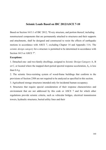
Occupancy CategoryzOccupancy category is defined inTable 1-1 in ASCE7-05.zThe values go from I to IV
Table 1-1 Occupancy Category
Table 1-1 Occupancy Category
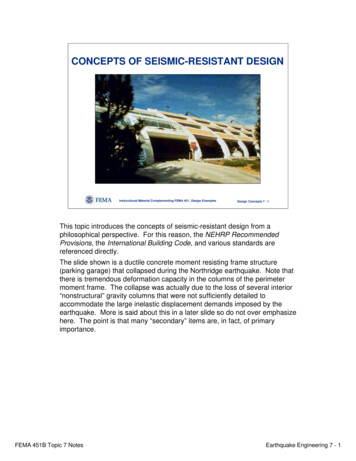
Seismic Design CategoryzSection 11.6 in ASCE 7-05– Occupancy Category I, II, or III whereS1 0.75 shall be Seismic DesignCategory E– Occupancy Category IV where S1 0.75shall be Seismic Design Category F
Seismic Design CategoryzSection 11.6 in ASCE 7-05– Otherwise pick the more severe optionfrom Tables 11.6-1 or 11.6-2– Other exceptions and conditions existconsult ASCE7-05 sections 11.6 and11.7 for specifics
Table 11.6-1 and Table 11.6-2
Seismic Hazard LevelzSeismic Hazard Level (SHL) is a termused in the SMACNA manual.zSHL Fp/Wpwhich CszSHL is the ratio of the seismic forceto the item’s weight.
TermszIt is not necessary for the contractorto fully understand the previousterms as these values should bedetermined by the designer.zA basic understanding of the termswill help the contractor determinewhen exceptions can be applied.
General Requirements1. Details provide lateral bracingsystem. Typical vertical supportsper local building code must beused.2. Thermal expansion not given butmust be considered.3. Duct construction to conform to theappropriate SMACNA publications.
General Requirements4. Pipes will conform to ANSI/ASME B31.9 Building Services Piping Code.5. Brace in-line equipmentindependently of ducts and pipes.6. Cold formed angles to conform to therequirements of the latest"Specifications for the Design ofCold-Formed Steel StructuralMembers" (AISI) (FY 33 KSI)
General Requirements7. Hot rolled shapes and plates toconform to ASTM A36. Pipes usedas braces to conform to ASTM A120or A53.8. Cables to have minimum breakingstrength. Per Table 3-2.
General Requirements9. Bolts to conform to ASTM A307.10. Expansion anchors per Table 3-3.Proprietary connectors may be usedwhere values are greater.11. Welding to conform to AWS D1.1 usingshielded or submerged ARC method.12. Brace conduit same as equivalentweight of pipe.
General Requirements13. Do not mix solid and cable bracing.14. Bracing for equipment NOT included.15. All runs will have a minimum of twotransverse and one longitudinalbraces.16. A run is defined as any change indirection except as allowed by offsets.
Bracing of DuctsSeismic supports are not required forHVAC ductwork when the Ip 1.0 ifeither of the following conditions ismet for the entire duct run:1. Ducts are suspended from hangers 12in. or less as measured from the topof the duct to the bottom of thesupport where
Bracing of Ductsthe hanger is attached. Hangers must bepositively attached to the duct within 2in. of the top of the duct with a minimumof two #10 sheet metal screws. Lateralmotion will not cause damaging impactwith other systems. Lateral motion willnot cause loss of vertical support.2. Ducts have a cross-sectional area of 6ft2 or less.** (less than 6 ft2 per ASCE7-05)
Code Changesz The third edition of the Seismic Restraint Manualwas written to be compliant with IBC 2006 andASCE 7-05.– The CBC 20071614A.1.14 ASCE 7 Section 13.6.7.» Modify ASCE 7 Section 13.6.7 by the following:Requirements of this section shall also apply for lp 1.5– The IBC 2009» 1613.6.8 HVAC ductwork with Ip 1.5. Seismic supportsare not required for HVAC ductwork with Ip 1.5 if either ofthe following conditions is met for the full length of eachduct run:» 1. HVAC ducts are suspended from hangers 12 inches (305mm) or less in length with hangers detailed to avoidsignificant bending of the hangers and their attachments,or» 2. HVAC ducts have a cross-sectional area of less than 6square feet (0.557 m2).– (expands the exceptions on previous slides)
Bracing of Ducts1. Transverse and longitudinalbracing per tables (Chapters 5, 6, 7and 8).2. Ducts may be grouped. Selectbracing requirements based oncombined weight. Minimum of twosides to be attached to horizontal orvertical angles.
Bracing of Ducts3. Wall penetrations may replacetransverse brace. Solid blockingrequired.
Bracing of Pipes or Conduit1. Brace fuel oil, and gas (such as, fuelgas, medical gas, and compressed air)as per local codes.2. Brace all pipes 3 inch nominaldiameter or larger.
Bracing of Pipes - Conduit3. Transverse and longitudinal bracing asper tables (Chapters 5, 6, 7 and 8).4. Provide joints/connections capable ofaccommodating seismic displacementswhere pipes pass through buildingseismic or expansion joints or wherepipes connect to equipment withvibration isolators.
Bracing of Pipes - Conduitz Seismic supports are not requiredfor piping systems where one of thefollowing conditions is met:1. Piping is supported by rod hangers;hangers in the pipe run are 12 in. (305mm) or less in length from the top ofthe pipe to the supporting structure;
Bracing of Pipes - Conduit1. hangers are detailed to avoid bendingof the hangers and their attachments;and provisions are made for piping toaccommodate expected deflections.2. High-deformability piping is used;provisions are made to avoid impactwith larger piping or mechanical
Bracing of Pipes - Conduit2. components or to protect the piping inthe event of such impact; and thefollowing requirements are satisfied:a) For Seismic Design Categories D, E or Fwhere Ip is greater than 1.0, the nominalpipe size shall be 1 in. (25 mm) or less.
Bracing of Pipes - Conduitb) For Seismic Design Category C, where Ipis greater than 1.0, the nominal pipe sizeshall be 2 in. (51 mm) or less.c) For Seismic Design Category D, E or Fwhere Ip is equal to 1.0, the nominal pipesize shall be 3 in. (76 mm) or less.
Bracing of Pipes - ConduitzzzDuctile pipes shall be braced as outlined inthe manual when using brazed or weldedconnections (Copper, Ductile Iron, aluminum,or steel)Non-ductile pipes or pipes using screwconnections (cast iron, no hub, PVC) shallreduce the brace spacing by ½ of thespacing allowed in the manual.CBC 2007 allows screw connections to be inthe ductile category if the piping is ductile
CBC 2007z 1614A.1.13 ASCE 7, Section 13.6.1.Modify ASCE 7 Section 13.6.1 by adding Sections 13.6.1.1 and13.6.1.2 as follows:13.6.1.1 HVAC ductwork, plumbing/piping and conduit systems.Ductwork shall be constructed in accordance with provisionscontained in Part 4, Title 24, California Mechanical Code. Wherepossible, pipes, conduit and their connections shall beconstructed of ductile materials (copper, ductile iron, steel oraluminum and brazed, welded or screwedconnections). Pipes, conduits and their connections,constructed of non-ductile materials (e.g., cast iron, no-hub pipeand plastic), shall have the brace spacing reduced to satisfyrequirements of ASCE 7 Chapter 13 and not to exceed onehalf of the spacing allowed for ductile materials.
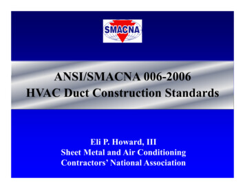
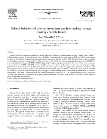
Vertical risers not specificallyengineered will be laterallysupported with a riser clamp ateach floor.
Figure 10-10 Riser Bracing for Hubless Pipe
DEFINITIONSzTRANSVERSE BRACE - thosedesigned and installed to restrainmovement in the directionperpendicular to the piping or ductrun
DEFINITIONSzLONGITUDINAL BRACE - thosedesigned and installed to restrainmovement in the direction parallel tothe piping or duct runzRUN (Piping or Duct) - a straightlength with no changes in directionexcept as allowed by offsets
Elements of a SeismicRestraintzBracezAttachment to theComponentzAttachment to the Structure
Bracing MembersRIGIDzAngleszPipeszStrut ChannelsNON-RIGIDzCables
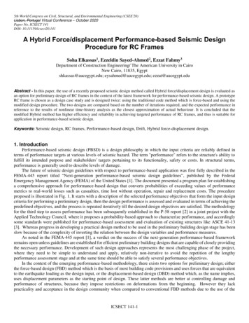
Connections to DuctszThe SMACNA Seismic RestraintManual Contains 12 DifferentDetails for Connecting toDuctwork, Rectangular andRound
FIGURE 4-2 SIDE BRACING FOR RECTANGULAR DUCTS
NoteszThe notes are specific to eachdrawing these are just a typicalrepresentation.
FIGURE 4-3 SIDE BRACING FOR RECTANGULAR DUCTS
FIGURE 4-4 CABLE SIDE BRACING FOR RECTANGULAR DUCTS
FIGURE 4-5 SIDE BRACING FOR RECTANGULAR DUCTS
FIGURE 4-6 CENTER BRACING FOR RECTANGULAR DUCTS
FIGURE 4-7 CABLE CENTER BRACING FOR RECTANGULAR DUCTS
FIGURE 4-8 FLOOR SUPPORTED DUCT
FIGURE 4-8 FLOOR SUPPORTED DUCT
FIGURE 4-9 SINGLE HANGER SPACING FOR ROUND DUCTS33-36 INCHES (838-900 MM)
FIGURE 4-10 SINGLE HANGER CABLE BRACING FOR ROUND DUCTS33-36 INCHES (838-900 MM)
FIGURE 4-11 DOUBLE HANGER BRACING FOR ROUND DUCTSUP TO 84 INCHES (2100 MM)
FIGURE 4-12 DOUBLE HANGER CABLE BRACING FOR ROUND DUCTS33-36 INCHES (838-900 MM)
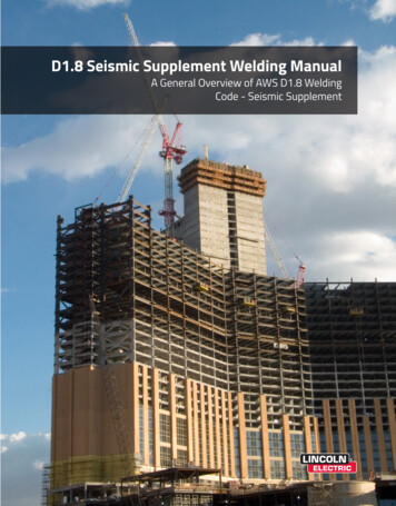
Connections to Piping/ConduitSystemszThe SMACNA Seismic RestraintManual Contains 10 DifferentDetails for Connecting toPiping/Conduit Systems
FIGURE 4-13 TRANSVERSE BRACING FOR PIPES
FIGURE 4-14 TRANSVERSE STRUT BRACING FOR PIPES
FIGURE 4-15 ALTERNATE ATTACHMENT TO HANGER FOR PIPE BRACING
FIGURE 4-16 LONGITUDINAL BRACING FOR PIPES
FIGURE 4-17 ALTERNATE BRACING FOR PIPES
FIGURE 4-18 TRANSVERSE CABLE BRACING FOR PIPES
FIGURE 4-19 LONGITUDINAL CABLE BRACING FOR PIPES
FIGURE 4-20 STRUT BRACING FOR PIPE TRAPEZE
FIGURE 4-21 CABLE BRACING FOR PIPE TRAPEZE
FIGURE 4-22 FLOOR SUPPORTED PIPES
Connections to theStructurezThe SMACNA Seismic RestraintManual Contains 8 Levels forConnection into Concrete(2) 1 Bolt Connection(3) 2 Bolt Connections(3) 4 Bolt Connections
Connections to theStructurezThe SMACNA Manual Contains(6) Alternative Connections toConcrete(6) Details for Connection to Steel(3) Details for Connections to Wood
CONNECTIONS TO STRUCTURES
CONNECTIONS TO STRUCTURES
CONNECTIONS TO STRUCTURES
CONNECTIO
systems are not covered in SMACNA’s seismic . of the duct to the bottom of the support where . Bracing of Ducts the hanger is attached. Hangers must be positively attached to the duct within 2 in. of the top of the duct with a minimum of two #10 sheet metal screws. Lateral motion will not cause damaging impact with other systems. Lateral motion will not cause loss of vertical support. 2 .