Transcription
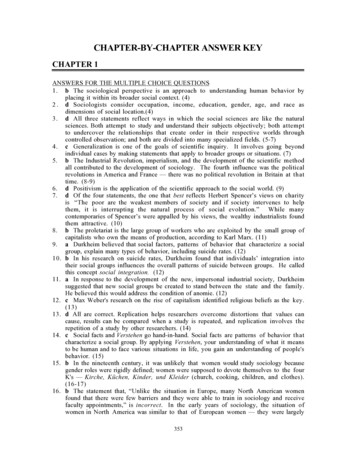
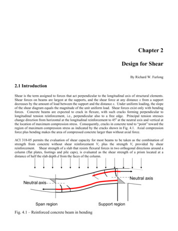
Chapter 4Design of Slender ColumnsBy Murat Saatcioglu14.1 IntroductionThe majority of reinforced concrete columns in practice are subjected to very little secondary stressesassociated with column deformations. These columns are designed as short columns using the columninteraction diagrams presented in Chapter 3. Rarely, when the column height is longer than typicalstory height and/or the column section is small relative to column height, secondary stresses becomesignificant, especially if end restraints are small and/or the columns are not braced against side sway.These columns are designed as "slender columns." Fig. 3.1 eloquently illustrates the secondarymoments generated in a slender column by P-Δ effects. Slender columns resist lower axial loads thanshort columns having the same cross-section. Therefore, the slenderness effect must be considered indesign, over and above the sectional capacity considerations incorporated in the interaction diagrams.The significance of slenderness effect is expressed through slenderness ratio.4.2 Slenderness RatioThe degree of slenderness in a column is expressed in terms of "slenderness ratio," defined below:Slenderness Ratio: kl u / rwhere, l u is unsupported column length; k is effective length factor reflecting the end restraint andlateral bracing conditions of a column; and r is the radius of gyration, reflecting the size and shape of acolumn cross-section.4.2.1 Unsupported Length, l uThe unsupported length l u of a column is measured as the clear distance between the underside of thebeam, slab, or column capital above, and the top of the beam or slab below. The unsupported length ofa column may be different in two orthogonal directions depending on the supporting elements in1Professor and University Research Chair, Dept. of Civil Engineering, University of Ottawa, Ottawa, CANADA1
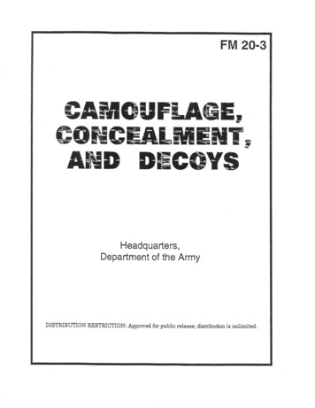
respective directions. Figure 4.1 provides examples of different support conditions and correspondingunsupported lengths ( l u ). Each coordinate and subscript “x” and “y” in the figure indicates the planeof the frame in which the stability of column is investigated.lulul uxlul uyFig. 4.1 Unsupported column length, l u4.2.2 Effective Length Factor, kThe effective length factor k reflects the end restraint (support) and lateral bracing conditions of acolumn relative to a pin-ended and laterally braced "reference column." The reference column, shownin Fig. 4.2(a), follows a half sine wave when it buckles, and is assigned a k factor of 1.0. Therefore, theeffective length k l u for this column is equal to the unsupported column length l u . A column with fully2
restrained end conditions develops the deflected shape illustrated in Fig. 4.2(b). The portion of thecolumn between the points of contraflexure follows a half sine wave, the same deflected shape as thatof the reference column. This segment is equal to 50% of the unsupported column length l u .Therefore, the effective length factor k for this case is equal to 0.5. Effective length factors for columnswith idealized supports can be determined from Fig. 4.2. It may be of interest to note that k variesbetween 0.5 and 1.0 for laterally braced columns, and 1.0 and for unbraced columns. A discussionof lateral bracing is provided in Sec. 4.3 to establish whether a given column can be considered to beas part of a sway or a non-sway frame.kl u l ulululukl u 0.5 l ukl uluk l u 2 .0 l ukl u l uFig. 4.2 Effective Length Factor k for Columns3
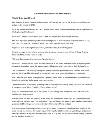
Most columns have end restraints that are neither perfectly hinged nor fully fixed. The degree of endrestraint depends on the stiffness of adjoining beams relative to that of the columns. Jackson andMoreland alignment charts, given in Slender Columns 4.1 and 4.2 can be used to determine theeffective length factor k for different values of relative stiffnesses at column ends. The stiffness ratiosψ A and ψ B used in Slender Columns 4.1 and 4.2 should reflect concrete cracking, and the effects ofsustained loading. Beams and slabs are flexure dominant members and may crack significantly morethan columns which are compression members. The reduced stiffness values recommended by ACI318-05 are given in Slender Columns 4.3, and should be used in determining k. Alternatively,Slender Columns 4.4 may be used to establish conservative values of k for braced columns2.4.2.3 Radius of Gyration, rThe radius of gyration introduces the effects of cross-sectional size and shape to slenderness. For thesame cross-sectional area, a section with higher moment of inertia produces a more stable column witha lower slenderness ratio. The radius of gyration r is defined below.r IA(4-1)It is permissible to use the approximations of r 0.3h for square and rectangular sections, and r 0.25h for circular sections, where “h” is the overall sectional dimension in the direction stability isbeing considered. This is shown in Fig. 4.3.Fig. 4.3 Radius of gyration for circular, square and rectangular sections4.3 Lateral Bracing and Designation of Frames as Non-SwayA frame is considered to be "non-sway" if it is sufficiently braced by lateral bracing elements likestructural walls. Otherwise, it may be designated as a "sway" frame. Frames that provide lateralresistance only by columns are considered to be sway frames. Structural walls that appear in the formof elevator shafts, stairwells, partial building enclosures or simply used as interior stiffening elementsprovide substantial drift control and lateral bracing. In most cases, even a few structural walls may besufficient to brace a multi-storey multi-bay building. The designer can usually determine whether theframe is non-sway or sway by inspecting the floor plan. Frames with lateral bracing elements, wherethe total lateral stiffness of the bracing elements provides at least six times the summation of thestiffnesses of all the columns, may be classified as non-sway. ACI 318-05 permits columns to bedesigned as part of a non-sway frame if the increase in column end moments due to second-order2“Concrete Design Handbook,” Cement Association of Canada, third edition, 60 Queen Street, Ottawa, ON., Canada, K1P5Y7, 2005.4
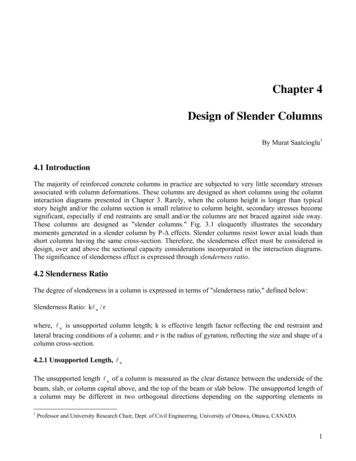
effects does not exceed 5% of the first-order end moments (Sec. 10.11.4.1). Alternatively, Section10.11.4.2 of ACI 318-05 defines a stability index "Q" (given in Eq. 4.2), where, Q 0.05 indicates anon-sway column. Pu ΔoQ (4.2)Vus l cWhere, Puis total factored axial load acting on all the columns in a story, Vus is total factored storyshear, Δo is lateral story drift (deflection of the top of the story relative to the bottom of that story) dueto Vus. The story drift Δ o should be computed using the modified EI values given in Slender Columns4.3 with βd defined as the ratio of the maximum factored sustained shear within a story to themaximum factored shear in that story. If Q exceeds approximately 0.2, the structure may have to bestiffened laterally to provide overall structural stability.4.4 Design of Slender ColumnsDesign of a slender column should be based on a second-order analysis which incorporates membercurvature and lateral drift effects, as well as material non-linearity and sustained load effects. Analternative approach is specified in ACI 318-05 for columns with slenderness ratios not exceeding 100.This approach is commonly referred to as the "Moment Magnification Method," and is based onmagnifying the end moments to account for secondary stresses. The application of this procedure isoutlined in the following sections.4.4.1 Slender Columns in Non-Sway FramesSlenderness effects may be neglected for columns in non-sway frames if the following inequality issatisfied:kl u 34 12( M 1 / M 2 )(4-3)r( 34 12 M 1 / M 2 ) 40(4-4)WhereM1/M2 is the ratio of smaller to larger end moments. This ratio is negative value when the column isbent in double curvature and positive when it is bent in single curvature. Fig. 4.4 illustrates columns indouble and single curvatures. Columns in non-sway frames are more stable when they bend in doublecurvature, with smaller secondary effects, as compared to bending in single curvature. This is reflectedin Eq. (4-3) through the sign of M1/M2 ratio. For negative values of this ratio the limit of slenderness inEq. (4-3) increases, allowing a wider range of columns to be treated as short columns.Slender columns in non-sway frames are designed for factored axial force Pu and amplified momentMc. The amplified moment is obtained by magnifying the larger of the two end moments M2 to accountfor member curvature and resulting secondary moments between the supports, while the supports arebraced against sidesway. If Mc computed for the curvature effect between the ends is smaller than thelarger end moment M2, the design is carried out for M2.M c δ ns M 2(4-5)5
δ ns Cm 1 .0Pu1 0.75 Pc(4-6)The critical column load, Pc (Euler buckling load) is;Pc π 2 EI(kl u )2(4-7)Fig. 4.4 Columns in Single and Double CurvatureEI in Eq. (4-7) is computed either with due considerations given to the presence of reinforcement in thesection, as specified in Eq. (4-8), or approximately using Eq. (4-9).EI 0.2 Ec I g E s I se1 βd(4-8)where βd is the ratio of the maximum factored axial dead load to the total factored axial load. Themoment of inertia of reinforcement about the cross-sectional centroid (Ise) can be computed usingSlender Columns 4.5.EI 0.4 E c I g(4-9)1 βdNote that Eq. (4-9) can be simplified further by assuming βd 0.6, in which case the equationbecomes; EI 0.25EcIg.6
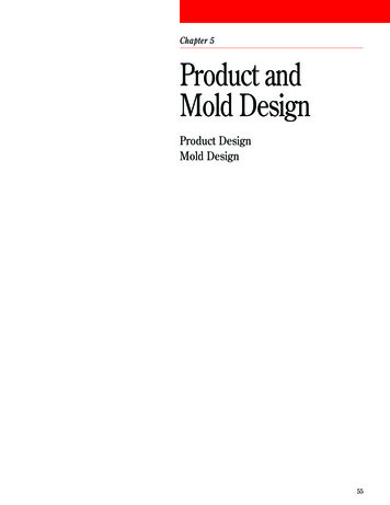
Coefficient Cm is equal to 1.0 for members with transverse loads between the supports. For the morecommon case of columns without transverse loads between the supports;C m 0.6 0.4M1 0.4M2(4-10)Where, M1/M2 is positive if the column is bent in single curvature.When the maximum factored end moment M2 is smaller than the minimum permissible design momentM2,min, specified in Eq. (4-11), the magnification applies to M2,min.M 2 ,min Pu ( 0.6 0.03h )(4-11)where h is the cross-sectional dimension in inches in the direction of the eccentricity of load. Forcolumns for which M2,min is higher than M2, the values of Cm, in Eq. (4-10) should either be taken 1.0or determined based on the computed ratio of end moments (M1/M2). Once the amplified moment Mcis obtained, the designer can use the appropriate interaction diagrams given in Chapter 3 to determinethe required percentage of longitudinal reinforcement.4.4.2 Slender Columns in Sway FramesColumns in sway frames are designed for the factored axial load Pu and the combination of factoredgravity load moments and magnified sway moments. This is specified below, and illustrated in Fig.4.5.M 1 M 1ns δ s M 1s(4-12)M 2 M 2 ns δ s M 2 s(4-13)where, M1ns and M2ns are end moments due to factored gravity loads; and M1s and M2s are swaymoments normally caused by factored lateral loads. All of these moments can be obtained from a firstorder elastic frame analysis. Magnified sway moments δsM1s and δsM2s are obtained either from asecond order frame analysis, with member flexural rigidity as specified in Slender Columnss 4.3, orby magnifying the end moments by sway magnification factor δs. The sway magnification factor iscalculated either as given in Eq. (4-14) or Eq. (4-15).δsM s Ms P1 0.75 P Ms(4-14)ucδsM s Ms Ms1 Q(4-15)7
However, if δs computed by Eq. (4-15) exceeds 1.5, δsMs shall be calculated either through secondorder analysis or using Eq. (4-14).Fig. 4.5 Design moments in sway framesIn a sway frame, all the columns of a given story participate in the sway mechanism, and play roles inthe stability of individual columns. Therefore, Eq. (4-14) includes Pu and Pc which give thesummations of factored axial loads and critical loads for all the columns in the story, respectively. Thecritical column load Pc can be computed using Eqs. (4-7) through (4-9) with the effective length factork computed for unbraced columns (for sway frames) and βd as the ratio of the maximum factored8
sustained shear within the story to the maximum total factored shear in the story. Eq. (4-14) providesan average δs for all the columns in a story. Therefore, it yields acceptable results if all the columns ina story undergo the same story drift. When significant torsion is anticipated under lateral loading, asecond order analysis is recommended for finding the amplified sway moment, δsMs.The magnification of moments through Eq. (4-15) is applicable only if the sway magnification factorδs does not exceed 1.5. If it does, then either the second-order analysis or Eq. (4-14) should beemployed (Sec. 10.13.4.2).The sidesway magnification discussed above is intended to amplify the end moments associated withlateral drift. Although the amplified end moment is commonly the critical moment for most swaycolumns, columns with high slenderness ratios may experience higher amplification of momentsbetween the ends (rather than at the ends) because of the curvature of the column along the columnheight. This is assumed to occur when the inequality given in Eq. (4-16) is satisfied.lu r35Puf ' c Ag(4-16)The magnification of moment due to the curvature of column between the ends is similar to that forbraced columns in non-sway frames. Therefore, if Eq. (4-16) is satisfied for a column, then the columnshould be designed for factored axial force Pu and magnified design moment (Mc) computed using Eqs.(4-5) and (4-6), with M1 and M2 computed from Eqs. (4-12) and (4-13).Sometimes columns of a sway frame may buckle under gravity loads alone, without the effects oflateral loading. In this case one of the gravity load combinations may govern the stability of columns.The reduction of EI under sustained gravity loads may be another factor contributing to the stability ofsway columns under gravity loads. Therefore, ACI 318-05 requires an additional check to safeguardagainst column buckling in sway frames under gravity loads alone (Sec. 10.13.6). Accordingly, thestrength and s
ACI 318-05 permits columns to be designed as part of a non-sway frame if the increase in column end moments due to second-order 2 “Concrete Design Handbook,” Cement Association of Canada, third edition, 60 Queen Street, Ottawa, ON., Canada, K1P 5Y7, 2005. 5 effects does not exceed 5% of the first-order end moments (Sec. 10.11.4.1). Alternatively, Section 10.11.4.2 of ACI 318-05 defines a .