Transcription
HAC2018 V Congreso Iberoamericano de HormigónAutocompactante y Hormigones EspecialesValencia, 5 y 6 de Marzo de 2018Ultra High Performance Concrete - Materials Formulationsand Serviceability based DesignYiming Yao (1), Aashay Arora (2), Narayanan Neithalath (3) and Barzin Mobasher (3)(1)(1)Associate Professor, Southeast University, Nanjing, Jiangsu, China.Graduate Research Assistant, School of Sustainable Engineering and the Built Environment,Arizona State University, Tempe, AZ, USA.(2)Professor, School of Sustainable Engineering and the Built Environment,Arizona State University, Tempe, AZ, USA.DOI: TMaterials and mechanical design procedures for ultra-high performance cement composites(UHPC) members based on analytical models are addressed. A procedure for the design ofblended components of UHPC is proposed using quaternary cementitious materials. Theblending procedures are used using a packing and rheology optimization approach to blendhigh performance mixtures using non-proprietary formulations. Closed-form solutions ofmoment-curvature responses of UHPC are derived based on elastic-plastic compressivemodel and trilinear strain hardening tension stress strain responses. Tension stiffeningbehavior of UHPC due to fiber toughening and distributed cracking is then incorporated inthe cross-sectional analysis. Load-deflection responses for beam members are obtainedusing moment-area, and direct integration approach. The proposed models provide insightsin the design of SHCC to utilize the hardening properties after cracking. Using properparameters, generalized materials model developed are applicable to both SHCC and strainsoftening cement composites such as steel fiber reinforced concrete (SFRC), textilereinforced concrete (TRC) and ultra-high performance concrete (UHPC).KEYWORDS: Strain hardening cement composites, distributed cracking, textilereinforced concrete, strain hardening, design.1.- INTRODUCTIONStrain hardening cement composite (UHPC) is a class of materials using relatively highfiber volume fraction (more than 2%) and exhibiting high strength and ductility. In contrastto conventional concrete, increases in tensile stresses are observed after first crack intension through crack bridging and interface transfer mechanisms provided by discretefibers. The UHPC class requires a fundamental concentration on the matrix phase and itsrheology in order to achieve high compressive strength and ductility. The durability ofEsta obra está bajo una Licencia Creative Commons (CC BY-NC-ND 4.0)EDITORIAL UNIVERSITAT POLITÈCNICA DE VALÈNCIA1
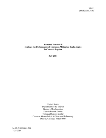
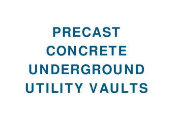
Ultra High Performance Concrete - Materials Formulations and Serviceability based DesignHAC2018 V Congreso Iberoamericano de Hormigón Autocompactante y Hormigones Especialesconcrete structures improves as a result of crack mitigation, where discrete cracks arereplaced with a system of distributed micro cracks.UHPC is an ideal construction material for applications that require rapid construction andconnection of precast segments, applications that require a reduction of the weight and sizeof structure, or for seismic design where high ductility is desired. Figure 1 shows theapplication of UHPC connection between precast deck panels [Greybeal, 2014]. Theimproved performance of SHCCs subjected fatigue and impact loads make them attractivefor industrial structures, highway pavements, bridges, and natural hazardous and extremeloads. In contrast to the design of conventional RC structures, implementation of UHPCrequires use of strain-hardening response that is attributed to multiple cracking due to loadtransfer by the fibers across the cracks (Mobasher et al. 2006b). As multiple cracking takesplace, the stiffness of the sample significantly drops while the crack spacing continuouslydecreases to a saturation level. The post crack stiffness and the ultimate strain capacity arefunctions of fiber type, stiffness, and bonding characteristics, however the stiffness in thepost crack region can be effectively used in the analytical and design formulations(Mobasher et al. 2006a).Figure 1. UHPC connection between precast deck panels as deployed by NYSDOTon I-81 in Syracuse, NY [Greybeal,2014]2.- MATERIALS DEVELOPMENTThe main objective is by controlled blending of components with up to 3% volume fractionof steel fibers, a UHPC formulation can be obtained with non-proprietary materials that isstrong, ductile, and durable. A systematic procedure was developed for a multiple (up tofour component) non-proprietary paste components that can be blended for optimalperformance. This paste system constitutes the main component of UHPC formulation,when used with specifically blended and sized aggregates of specified particle sizedistribution, it would yield the UHPC system.Figure 2 shows the strategy to obtain the optimized design of UHPC. The researchapproach is built around three fundamental steps: binder (paste) design, aggregate packingand optimization, and testing the final properties. The binder design, shown in Figure 2consists of selection of the source materials for the binder from a series of commoncementing (or cement replacement) materials. Ordinary Portland cement (OPC), Flyash,(F), MicroSilica, (M), Slag, (S), Metakaolin, (K), Limestone, (La, Lb, 3.0 and 1.5 micron).2Esta obra está bajo una Licencia Creative Commons (CC BY-NC-ND 4.0)EDITORIAL UNIVERSITAT POLITÈCNICA DE VALÈNCIA
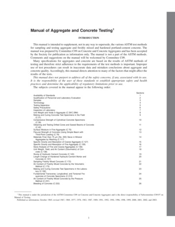
Yiming Yao, Aashay Arora, Narayanan Neithalath and Barzin MobasherHAC2018 V Congreso Iberoamericano de Hormigón Autocompactante y Hormigones EspecialesDifferent properties of the microstructure can be analyzed using the 3D particle packingmodels. 3D volumes are generated using a stochastic particle packing model assumingspherical particles.Figure 2. Schematic showing the aggregate packing of UHPCThe goal is to use a blend of the cementitious materials that can be mixed with a very loww/b ratio and, with the aid of superplasticizers, can result in flowable and workablemixtures. The microstructural packing and rheological studies provide preliminaryindicators as to the applicability of paste systems for UHPC. Packing influences rheologyand mechanical/durability properties, while rheology influences placing and early-agestructure development, which in turn influences the later age properties. In a compositebinder that contains particles of different size distributions and surface characteristics,chemical admixtures are essential in controlling the rheological features. One would startwith the materials (cement, fly ash, silica fume etc.) with particle sizes ranging from 0.1microns to 50 microns. Therefore F20L10b would indicate a blended composite cementwith 20% Flyash and 10% Limestone. The selected components and their mass fractionsare combined to ensure maximum packing of the powder ingredients. The flowability of thebinders at very low w/b, and in the presence of large amounts of chemical admixtures areevaluated using fundamental rheological experiments.In the second step, the optimized packing of selected coarse and fine aggregates and fibersare tested to meet the performance criteria. Selection of aggregates is based on acompressible packing model (CPM) which determines the maximum packing density usingdifferent sizes of coarse and fine aggregates. The packing efficiency reduces the capillarypores and therefore improves the strength and the impermeability significantly. This isshown in Figure 3(a). The finalized UHPC mixture(s) are then subjected to property-andperformance testing that includes mechanical testing (compression, tension, flexural,fracture) and durability evaluation (resistance to freezing and thawing, chloridepenetration). This approach shows that UHPC concrete mixtures can be developed usinglocally obtained materials. [Arora et. al, 2017]Esta obra está bajo una Licencia Creative Commons (CC BY-NC-ND 4.0)EDITORIAL UNIVERSITAT POLITÈCNICA DE VALÈNCIA3
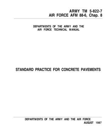
Ultra High Performance Concrete - Materials Formulations and Serviceability based DesignHAC2018 V Congreso Iberoamericano de Hormigón Autocompactante y Hormigones Especiales2.1.- Strength and Fracture responseFigure 3(b) shows the compressive strengths of mortars made using the selected UHPpastes after 14 and 28 days of moist curing. Even with a clinker factor reduction of 30%,the UHP mortars, especially the quaternary blends demonstrate 28 day strengths that arecomparable to, or higher than that of the control UHP mortar. The mixtures containing slagdemonstrate higher strengths than those containing fly ash at 28 days, but it is conceivablethat the pozzolanic reaction of fly ash and its later synergy with the other replacementmaterials could improve the strength with further curing. It is noted that the addition offibers, reduction of water to binder ratio, optimization of the aggregate size fractions wouldlead to a final mixture with 28 day compressive strengths in excess of 22,000 psi (150MPa).The flexural response results are shown in Figure 4. Note that the increase in strength bymeans of microsctructural modification is also complimentary to the role of fibers inincreasing the load carrying resistance and the strength hand ductility are both improvedwith the use of steel fibers. Figure 4.b shows the digital image correlation of the formationof multiple cracks in the flexural samples at various stages.Figure 3. a) Mercury intrusion porosity and critical pore diameters for selectedUHPC specimens b) compressive strengths at Day 14 andday 28 of selected UHP mortars.4Esta obra está bajo una Licencia Creative Commons (CC BY-NC-ND 4.0)EDITORIAL UNIVERSITAT POLITÈCNICA DE VALÈNCIA
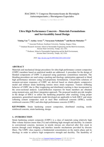
Yiming Yao, Aashay Arora, Narayanan Neithalath and Barzin MobasherHAC2018 V Congreso Iberoamericano de Hormigón Autocompactante y Hormigones Especiales400350OPC (Vf 1.0%)OPC (Control)300Load (N)25020015010050000.050.10.150.2CMOD (mm)0.250.3Figure 4. a) load vs. CMOD for control fiber reinforced beam specimenswith 1% steel fiber at a post peak stress of (a,b) 90% and(c,d) 50% of the peak stress.2.2.- Modeling and Structural Design of Strain-Hardening CompositesA broad range of cement composites exhibiting strain-hardening behavior can be modelledusing the proposed approach. These materials include textile reinforced concrete (TRC),fiber reinforced concrete (FRC), and ultra-high performance fiber reinforced concrete(UHPC). The general behavior can be simulated by linearized compression and tensionmodels that address nonlinear and hardening properties as shown in Figure 5 (Soranakomand Mobasher 2008). Tensile response is defined by Young’s Modulus E, first crack tensilestrain εcr, transition strain εtrn, and post crack modulus Ecr. Note that by normalizing allparameters by minimum number of independent and dimensionless variables, tensileresponse uses only two intrinsic material parameters E and εcr, therefore the softening orresidual range is defined by a constant stress level µEεcr, and the compressive strengthσcy ωγEεcr. Other material parameters are summarized as follows: α, μ, η, ω and definedEsta obra está bajo una Licencia Creative Commons (CC BY-NC-ND 4.0)EDITORIAL UNIVERSITAT POLITÈCNICA DE VALÈNCIA5
Ultra High Performance Concrete - Materials Formulations and Serviceability based DesignHAC2018 V Congreso Iberoamericano de Hormigón Autocompactante y Hormigones Especialesrespectively as normalized tensile strain at peak strength, residual tensile strength, postcrack modulus, and compressive yield strength (Soranakom and Mobasher 2008).(a)(b)Figure 5. Material model for SHCC (a) compression, (b) tensionmodel (Yao et al. 2017).Even though the tensile strength is greatly improved in SHCC, the compressive strength inis still much higher, and the flexural capacity is defined by means of the tensile variable.The nonlinearity and failure in flexure are likely to be dominated by tensile properties. Onecan perform cross-sectional analysis by constructing strain and stress profiles. Followed byintegration of normal stresses, the compressive and tensile force terms from each zone areobtained and bending moment on the cross section computed. Closed-form solutions ofmoment-curvature responses are explicitly derived based on interactions among differentstages in tension and compression models. The detailed derivations for strain softening,strain hardening FRC as well as hybrid reinforced concrete (HRC) sections containing rebarand fibers can be found in (Mobasher et al. 2015; Soranakom and Mobasher 2008). Theseequations can be further simplified using polynomial or power curve fitting with detailedapplications for individual cases presented in (Yao et al. 2017).The solution for the plain fiber reinforced concrete section is presented first. For the givenapplied strain distribution, the location of neutral axis, defined as kd is obtained from theforce equilibrium equations. For a specified serviceability limit based on maximumallowable compressive strain εc λcu εcr , the neutral axis depth and the bending momentare obtained as:k 2µλcu ω 2λcu (ω µ ) 2µ 12 k2M n ( 3ωλcu2 ω 3 3µλcu2 3µ 2 ) 2 3µ ( 2k 1) M cr λcu M cr 6σ cr bh 2(1)(2)(3)6Esta obra está bajo una Licencia Creative Commons (CC BY-NC-ND 4.0)EDITORIAL UNIVERSITAT POLITÈCNICA DE VALÈNCIA
Yiming Yao, Aashay Arora, Narayanan Neithalath and Barzin MobasherHAC2018 V Congreso Iberoamericano de Hormigón Autocompactante y Hormigones EspecialesOn may conduct an asymptotic analysis to compute the moment capacity in the limit case, asimplified design equation for normalized moment capacity is obtained. This resembles acase when the cracked section in flexure opens significantly to go beyond serviceabilitylimit, however due to the presence of fibers, the section can still transmit the flexural loadapplied. The moment capacity in this case is defined by the limit case of compressivecracking strain λcu reaching a relatively large number [1]. To further simplify Equation 2,The residual strength of FRC in flexure is approximately three times its residual strength intension, that is, f eq ,3 3µσ cr [ACI-544-8R [6], Mn. Furthermore, the empirical relationshipbetween tensile and compressive strength ft ' 6.7 fc ' (in U.S. customary units) is used fornormalized compressive strengthω: f c ' 0.85 f c '0.127 f c ' ( f c ' in psi ) γ Eωε cr ft ' 6.7 fc ' ω Eε cr f c ' 0.85 f c ' 1.518 f ' ( f c ' in MPa )c ft ' 0.56 f c ' (4)By substituting forω, as a function of ultimate compressive strength fc′ and the postcrack tensile strength µ the expression for nominal ultimate moment capacity isobtained. 6f eq,3 f c′Mn ξ ( f 3f ′ )eq,3c M , cr ξ 15.8 for U.S. units; ξ 1.32 for SI(5)The ultimate moment capacity as a function of residual tensile strength and reinforcementcan be used as a convenient design tool for combinations of reinforcements, calculated asshown in Eq. (6). An analytical expression for minimum reinforcement ratio ρg,min forconventional reinforced concrete is obtained. For example, using parameters µ 0, γ 3/4,and ω 6, Eq. (7) represents the minimum reinforcement as a function of location and itsstiffness (steel or FRP).M n m M crρ min (6ρ g nκ ( μα μ αω ) 3ωμ 3 ρ g nκ ω μ)2M cr9α 81α 2 62αnκEsta obra está bajo una Licencia Creative Commons (CC BY-NC-ND 4.0)EDITORIAL UNIVERSITAT POLITÈCNICA DE VALÈNCIA(6)(7)7
Ultra High Performance Concrete - Materials Formulations and Serviceability based DesignHAC2018 V Congreso Iberoamericano de Hormigón Autocompactante y Hormigones EspecialesFigure 6. Design chart for normalized ultimate moment capacity (determined atλ λcu) for different levels of post crack tensile strength µ andreinforcement ratio ρg.Equations to determine the moment-curvature relationship, ultimate moment capacity, andminimum flexural reinforcement ratio were also explicitly derived by Yao et al (2018).Figure 6 shows a design chart for the parametric design model with various grades of steel.Flexural design using this chart, requires ultimate moment Mu due to factored loadsnormalized with respect to cross-sectional geometry. The demand moment capacity Mu′ isobtained from this chart using a combination of normalized residual tensile strength µ,grade of steel, and reinforcement ratio ρg. Results are scaled to numerical values using thesection cracking moment Mcr.3.- MOMENT-CURVATURE AND LOAD-DEFLECTION RELATIONSHIPSMoment-curvature relationship as cross sectional properties connects the constitutivematerial parameters to the structural flexural behavior, equilibrium, and the curvaturedisplacement relationship. This design parameter can be represented in various forms ofbilinear, tri-linear, or curve fit from various sections (Soranakom and Mobasher 2008;Wang 2015). To obtain load-deflection calculations with given moment-curvature response,two approaches can be applied to the slope deflection equation: direct integration andpolynomial/piecewise integration of linearized segments as discussed in (Soranakom andMobasher 2008). Alternatively, one can use a parameterized moment-curvature relationshipfor a generalized solution, which has been derived and proposed as a practical design toolWang (2015), Yao et al, (2018).8Esta obra está bajo una Licencia Creative Commons (CC BY-NC-ND 4.0)EDITORIAL UNIVERSITAT POLITÈCNICA DE VALÈNCIA
Yiming Yao, Aashay Arora, Narayanan Neithalath and Barzin MobasherHAC2018 V Congreso Iberoamericano de Hormigón Autocompactante y Hormigones EspecialesFigure 7. Simplified parametric moment-curvature relationship: (a) bilinearrepresentation, (b) dimensionless moment-curvature curverepresented as variables (κ, m).Figure 7a and 7b presents the idealized parametric moment–curvature response of adeflection hardening case with a two stage linear elastic and a post-cracking range. Themid-span deflection is obtained directly using the double integration of curvaturedistribution and imposing boundary conditions to ensure the continuity of displacementfields (Wang 2015). Deflection distributions along the beams at full range of applied loadswere derived for various beam types, loading conditions and supports such as simple beam,cantilever beam, point load/moment, distributed load and combination of them. Analyticalexpressions of the mid-span deflections for 3PB and 4PB are presented for elastic (Stage 1)and cracked (Stage 2) stages. where Le a / m refers to the length of elastic region, and ais the shear span of 4PB beam.3PB:δ1 δ2 κ12ϕcr L2ϕcr L2 (κ 1) L L 2 Le 24 ( 2 Le L ) κ L2e ( L 2κ Le ) 86 L2(8) a 2 L2 δ1 κϕcr 6 8 4PB: 1 3L κ 3κ Le 1 κ ϕcr L2δ 2 e 1 L 8 54 LEsta obra está bajo una Licencia Creative Commons (CC BY-NC-ND 4.0)EDITORIAL UNIVERSITAT POLITÈCNICA DE VALÈNCIA(9)9
Ultra High Performance Concrete - Materials Formulations and Serviceability based DesignHAC2018 V Congreso Iberoamericano de Hormigón Autocompactante y Hormigones Especiales4.- MODEL SIMULATIONTo verify the analytical model for flexural results of SHCC and UHPC beams studied byQian and Li (2008), and Yoo et al. (2016) are simulated. Plain beam specimens of bothSHCC and UHPC had a rectangular cross section of 100x100 mm2 and a span of 300 mm.Four-point bending tests were conducted and load and deflection responses were recorded.The compressive strength for the UHPC and SHCC specimens are 232 MPa and 46 MPa,respectively.4018Tensile Stress, MPa15Flexural Stress, MPaεcr 230µε, Ε 47GPa, α 90,ω 20, η 0.004, µ 0.65129Tension Model6ECC (Qian and Li 2008)UHPC (Yoo et al. 2016)30εcr 160µε, Ε 20GPa, α 80,ω 12, η 0.003, µ 1.2100.010.02Tensile Strain, mm/mm0.0330Flexural Model20ECC (Qian and Li 2008)UHPC (Yoo et al. 2016)1000123Deflection, mm45Figure 8. Simulations of ECC and UHPC specimens (a) tension models, (b) flexuralstress-deflection responses.Figures 8(a) and (b) compare the tensile stress-strain and flexural stress-deflectionresponses, respectively, for SHCC and UHPC composites. For SHCC, the modelparameters include cracking strain εcr 160με, Young’s modulus E 20GPa, normalizedtransition strain α 80, normalized compressive strength ω 12, post-cracking stiffnessη 0.003. For UHPC specimens, these values are εcr 230με, E 47 GPa, α 90, ω 20,η 0.004, as indicated in Figure 8(a). Strain hardening was demonstrated in both systemswhile UHPC showed much higher crack and ultimate tensile strength due to improvedmatrix properties and use of steel fibers. Use of ductile PVA fibers in SHCC results in morepronounced ductility in tension and flexure. The tension models in Figure 8(a) are used toconstruct the moment-curvature relationship and the deflection equations. The applied loadis obtained from static equilibrium of a 4PB beam while the mid-span deflections areobtained from curvature. The simulated load-deflection responses are compared withexperimental results in Figure 8(b). Deflection hardening are showed by both materials inbending due to distributed flexural cracking. The analytical model agrees well with theexperimental data.10Esta obra está bajo una Licencia Creative Commons (CC BY-NC-ND 4.0)EDITORIAL UNIVERSITAT POLITÈCNICA DE VALÈNCIA
Yiming Yao, Aashay Arora, Narayanan Neithalath and Barzin MobasherHAC2018 V Congreso Iberoamericano de Hormigón Autocompactante y Hormigones EspecialesFigure 9. (a) Geometry of the cross section of UHPC beams, b) beam and loadinggeometry, c) Normalized moment-curvature relationship, d) comparison of loaddeflection responses between simulation and experimentaldata for ρ 0.94%, and ρ 1.50%.In the second simulation test results of hybrid reinforced concrete beams with UHPC andcombinations of rebar and steel fiber tested by Yoo and Yoon, (2015). The beams with across section of 150 mm by 220 mm are tested under 4PB and span of 2200 mm are shownin Figures 9(a) and 9(b). Effect of longitudinal reinforcement ratio was evaluated at 0.94%and 1.50%. Two distinct types of smooth and twisted steel fibers at volume fraction of 2%were used. Figure 9(c) shows the normalized moment-curvature responses and Figure 9(d)compares the predicted and experimental load-deflection responses for of ρ 0.94% and1.50%, respectively. The basic material parameters used in the model include Young’smodulus E 47GPa, first crack tensile strain εcr 180με. Other model parameters shown inthe Figure. Note that the proposed model provides conservative estimation for this class ofmaterials, a preferred feature from the design perspective.4.- CONCLUSIONSA procedure for the design of blended components of UHPC was developed for usingquaternary cementitious materials. The blending procedures use packing and rheologyoptimization approach to blend high performance mixtures using non-proprietaryformulations. Tension hardening and multiple cracking behavior were obtained by theEsta obra está bajo una Licencia Creative Commons (CC BY-NC-ND 4.0)EDITORIAL UNIVERSITAT POLITÈCNICA DE VALÈNCIA11
Ultra High Performance Concrete - Materials Formulations and Serviceability based DesignHAC2018 V Congreso Iberoamericano de Hormigón Autocompactante y Hormigones Especialesdeflection hardening mechanisms and energy dissipation in flexural members made withUHPC was documented. An analytical model based on serviceability limits for design ofFRC and UHPC members is presented. Load-deflection responses are obtained usingmoment-area method or in closed-form by means of a linearized moment-curvature anddouble integration. The proposed models were verified by several experimental studies.REFERENCESArora, A., Aguayo, M., Hansen, H., Castro, C., Federspiel, E., Mobasher, B., Neithalath,N., “ Microstructural packing and rheology-based binder selection and characterizationfor Ultra-high Performance Concrete (UHPC)“ , Cement and Concrete Research 103,179-190, 2018Aswani, K. (2014). “Design procedures for Strain Hardening Cement Composites (SHCC)and measurement of their shear properties by mechanical and 2-D Digital ImageCorrelation (DIC) method.” Arizona State University, Master Thesis.Facconi, L., Minelli, F., and Plizzari, G. (2016). “Steel fiber reinforced self-compactingconcrete thin slabs – Experimental study and verification against Model Code 2010provisions.” Engineering Structures, 122, 226–237.Graybeal, B. (2014). Design and construction of field-cast UHPC Connections (No.FHWA-HRT-14-084).Johansen, K. W. (1962). Yield-line theory. Cement and Concrete Association, London.Khaloo, A. R., and Afshari, M. (2005). “Flexural behaviour of small steel fibre reinforcedconcrete slabs.” Cement and Concrete Composites, 27(1), 141–149.Kim, J., Kim, D. J., Park, S. H., and Zi, G. (2015). “Investigating the flexural resistance offiber reinforced cementitious composites under biaxial condition.” CompositeStructures, 122, 198–208.Mobasher, B. (2011). Mechanics of Fiber and Textile Reinforced Cement Composites.CRC Press.Mobasher, B., Pahilajani, J., and Peled, A. (2006a). “Analytical simulation of tensileresponse of fabric reinforced cement based composites.” Cement and ConcreteComposites, 28(1), 77–89.Mobasher, B., Peled, A., and Pahilajani, J. (2006b). “Distributed cracking and stiffnessdegradation in fabric-cement composites.” Materials and Structures, 39(3), 317–331.Mobasher, B., Yao, Y., and Soranakom, C. (2015). “Analytical solutions for flexural designof hybrid steel fiber reinforced concrete beams.” Engineering Structures, 100, 164–177.12Esta obra está bajo una Licencia Creative Commons (CC BY-NC-ND 4.0)EDITORIAL UNIVERSITAT POLITÈCNICA DE VALÈNCIA
Yiming Yao, Aashay Arora, Narayanan Neithalath and Barzin MobasherHAC2018 V Congreso Iberoamericano de Hormigón Autocompactante y Hormigones EspecialesQian, S., and Li, V. C. (2008). “Simplified Inverse Method for Determining the TensileProperties of Strain Hardening Cementitious Composites (SHCC).” Journal ofAdvanced Concrete Technology, 6(2), 353–363.Sawyer, H. A. J. (1965). “Design of Concrete Frames For Two Failure Stages.” SpecialPublication, 12, 405–437.Soranakom, C., and Mobasher, B. (2008). “Correlation of tensile and flexural responses ofstrain softening and strain hardening cement composites.” Cement and ConcreteComposites, 30(6), 465–477.Wang, X. (2015). “Analytical Load-Deflection Equations for Beam and 2-D Panel with aBilinear Moment-Curvature Model.” Master Thesis, ARIZONA STATEUNIVERSITY.Yao, Y., Wang, X., Aswani, K., and Mobasher, B. (2017). “Analytical procedures fordesign of strain softening and hardening cement composites.” International Journal ofAdvances in Engineering Sciences and Applied Mathematics, 1–14.Yoo, D.-Y., Banthia, N., Kang, S.-T., and Yoon, Y.-S. (2016). “Size effect in ultra-highperformance concrete beams.” Engineering Fracture Mechanics, 157, 86–106.Yoo, D. Y., & Yoon, Y. S. (2015). Structural performance of ultra-high-performanceconcrete beams with different steel fibers.”Engineering Structures,”102, 409-423.Esta obra está bajo una Licencia Creative Commons (CC BY-NC-ND 4.0)EDITORIAL UNIVERSITAT POLITÈCNICA DE VALÈNCIA13
Yiming Yao, Aashay Arora, Narayanan Neithalath and Barzin Mobasher HAC2018 V Congreso Iberoamericano de Hormigón Autocompactante y Hormigones Especiales Esta obra está bajo una Licencia Creative Commons (CC BY-NC-ND 4.0) EDITORIAL UNIVERSITAT POLITÈCNICA DE VALÈNCIA Figure 4. a) load vs. CMOD for control fiber reinforced beam specimens