Transcription
GE Oil & GasGrounding Requirements for MachineryInstrumentation and Noise Case StudiesTable of Contents1 Purpose.26 Field Grounding Checks and Tests.62 Scope.27 Case Studies.73 Definitions.27.1 Spurious Noise Experienced on GE’s Gas Turbine PowerGeneration System.74 Grounding Problem Indicators.25 Grounding Practices.35.1 Basics .3Grounding Terminology:.35.2 Plant Ground Types.4Mains Supply and Large Equipment/Dirty Grounds.47.2 High Vibration Alarms Experienced on 650 MWSteam Turbine Generator .7Appendix 1: Testing 120V AC Power on Sites.8Appendix 2: Suggested Tool Kit.9References.9Instrument/Clean Grounds.4Structural Grounds.4Star Point/Single Point Grounding.55.3 Grounding Concerns.55.4 Example of Proper Field Wiring.65.5 Example of Improper Filed Wiringwith Potential Ground Loops.6application note
application note1 PurposeThis document describes recommended grounding practicesas applicable to Bently Nevada* vibration monitoring systems.It also defines common terms, identifies potential sourcesof noise, describes basics of a plant grounding system, explainsground loops, and presents a troubleshooting guide to helplocate a noise/ground issue and then eliminate it fromthe system.4 Grounding Problem IndicatorsIssue/IndicatorDetailsVariable Locations,Not Easy toDuplicateGrounding problems can sometimesappear to move around and may not beeasily and consistently duplicated.Loose Shields,Improper WiringLoose or improperly connected shieldsand improper wiring are leading causesof noise/grounding issues. Each shieldwire should be insulated along its lengthand only make contact to ground at asingle point, the monitor.Grounds andBonding JumperConnectionsFailure to understand and diagramALL grounds and bonding jumpersconnected to the rack or cabinet can leadto incorrect and duplicate connections.A voltage potential between the groundpoints will cause any loop that exists tocarry current. These ground currentsmay affect the systems performance.Multiple GroundConnectionsMultiple connections to ground will eachcarry current and form voltage potentialsacross parasitic impedances in thoseconnections, unbalancing ground pointsgenerally considered equipotential, andthereby often affecting the system asa whole.2 ScopeBecause issues related to grounding are broad and deep inscope, this document only describes grounding issues as theyapply specifically to a Bently Nevada monitoring system.Disclaimer - This guide presents and describes known andpotential grounding issues with Bently Nevada products. It isnot intended to replace or supersede any local, national, orinternational electrical safety standards. Always follow theNational Electric Code or equivalent when designing orimplementing grounding and bonding schemes.3 Definitions0V – True 0 voltage.Ground – True 0V reference. A ground connection froman instrument is a green wire or green with yellow stripwire connected to earth and will only carry current underfault conditions.Neutral – A power system conductor that normallycarries current and is connected to earth ground at themain electrical panel.Earth – All grounds are ultimately tied to 0V referenceat the planet earth (exceptions are ships, airplanes, andspace craft).Protective Earth (PE) – Central plant ground point to whichall equipment will ultimately connect. This serves not only as asystem level reference for voltage potential, but also providesthe final location for transient electrical currents to travel.Chassis – The metallic enclosure of a system or pieceof electrical gear such as the 3500 Series monitoring systemmetal enclosure.Ground Loop – An unwanted electrical current path in acircuit that can cause interference. Ground loops frequentlyoccur when two points that are thought to be at the samepotential, but are not, are connected together.Common – The internal 0V reference point for internal circuitswithin a system, also known as signal common.Bonding – The physical low impedance connection betweentwo electrical conductors such as exposed metallic items in abuilding or instrument. Bonding must be sufficiently robustto carry the maximum electrical fault current to the 0V groundpoint thus activating protective fuses and/or breakers to protectagainst electrical shock.2Similarly, multiple connections to groundcan be effected by electromagneticenergy causing a potential differencebetween the connections, resulting inunintended current flowing throughthe grounding conductors. The voltagepotential difference can also causesystem problems, as the referencepotential for different parts of thesystem varies from one point to another.A 60 or 50 Hertz (3600 or 3000 CPM)signal that is unrelated to machinevibration is a common example ofan issue that may be caused by aground loop.
application note5 Grounding Practices5.1 BasicsA primary purpose for grounding of electronic equipment ispersonal safety. A properly installed safety ground on electronicequipment allows faults to be cleared by the fast opening ofcircuit breakers or fuses and is no different than that of otherequipment. Safe grounding results in all exposed metal surfaceson the electrical system and equipment staying below levels thatpeople can safely contact.System Threats: Electronic systems’ circuit components can besensitive to relatively small transient currents and voltages. Theinherent nature of solid-state devices allows them to respondvery fast; this means that they can be affected by short durationelectrical disturbances that are difficult to capture on analysisinstrumentation. Interestingly, lightning is a slow transientcompared to the response of almost any electronic device,and lightning impulses often cause a signal response in nearbyelectronics. Typical threats to proper operation of electronicdevices and systems include: Lightning – Direct strikes, but also induced currents andvoltage generated by overhead cloud-to-cloud discharges,and nearby lightning strikes. Switching transients – From power network operations andpower factor capacitor switching, lightning arrestor operation,and fault clearing activities on nearby power circuits. Static electricity – Directly applied static discharges tothe equipment, or static discharges to nearby equipment.Note: Charges build up on rotating shafts of motors,generators, and steam turbines with resultingESD discharges.Electrical fast transients – Typically caused by arcingcontacts or collapsing magnetic fields in the coils ofcontactors in equipment – usually very near the affectedequipment or field wiring.Controlling Transient Effects: A Bently Nevada system failing toperform as expected may be due to electrical noise associated withgrounding problems. Grounding problems frequently are exposedby the presence of fast electrical transients. Their occurrence maybe random in time and frequency of occurrence, making the solvingof transient-induced problems very difficult. In general, they havewave shapes that are not easily captured or analyzed. However,the effects of transients can be controlled, or at least reduced, byfollowing the four general rules below:1.Limit overvoltages (surge voltages) on the AC powerconductors with surge protective devices (SPDs).2.Reduce the chances of electrical noise on the power circuitsconnected to electronic equipment and the data signal circuitcables that interconnect the units of equipment. This can oftenbe accomplished by observing the requirements for properrouting and grounding of field wiring and branch circuitsalong with ensuring adequate separation of power anddata signal wiring.3.Enable proper application of signal shielding by groundingat just a single point, on the monitor.4.Ensure proper grounding through the correct installation ofequipment grounding conductors of all types, and neutralterminal grounding and bonding at the service entrance,and for separately derived AC systems.Vibration Monitoring System Installation: While the aboverecommendations are all within the scope of the equipmentinstallation contractor’s job, GE’s Bently Nevada personnelmust review and provide expert input regarding the properinstallation of the vibration monitoring system. The vibrationmonitoring system is defined as all the equipment and wiringfrom the transducer (or probe) to the System 1* server. Iferrors occur during system installation, extensive effort andexpenditures may be required to repair the installation and getthe vibration monitoring system operating properly. Even worse,errors may not be detected until after system commissioning,often requiring difficult troubleshooting to determine thesource of encountered problems.Grounding Terminology:Ground (Earth) – In electrical engineering, ground or earth isthe reference point in an electrical circuit from which voltagesare measured, a common return path for electric current, or adirect physical connection to the Earth. Electrical circuits may beconnected to ground for several reasons.Ground Bus – A heavy solid copper bar with many locationswhere ground leads can be terminated. A large conductor isrouted from the bus bar to the plant 0V point.Dirty Ground – A ground bus that carries the large electricalcurrents from heavy machinery. This ground could be in a MotorControl Center (MCC) where motors are turned on and off wherelarge current and voltage surges are possible. A separate conductoris run from the MCC dirty ground bus to the 0Vearth ground at thepower input panel.Clean Ground – A ground bus separated from all heavy electricalloads with a separate conductor run from the clean ground bus tothe 0V plant ground.I.S. Ground – An Intrinsic Safe (I.S.) Ground is required to assurea single point ground for use with systems that interface withequipment in potentially hazardous areas.N-E Ground – The ground connection at the power main inputpanel where the transformer neutral is connected to the plant0V ground grid.MCC Ground – The Motor Control Center from which high voltageand current devices are managed. This ground bus can experiencevoltage spikes due to motor start-ups, contactors opening andclosing, relays making and breaking, and so on.Instrument System Ground – A ground bus where instrumentsrequiring a clean ground are connected with a separate conductorrun to the 0V plant ground.Lighting CC – A control center (CC) similar to the MCC controlcenter. This ground bus is separately connected to the 0V point.3
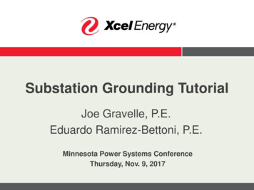
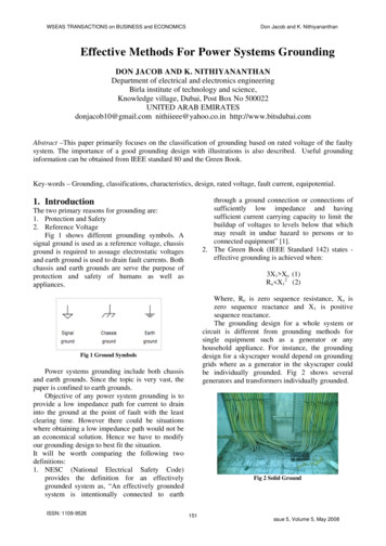
application notePLC, PLC Systems, Etc. – Ground buses that may be dedicatedto a particular group of instrumentation, such as within aBently Nevada instrument cabinet, and then connected to aclean instrumentation bus.SE Bar – A bonding of the structural frame of the building thatis tied directly to the 0V point.Instrument/Clean GroundsExamples of clean grounds are the DC grounds – usually24 VDC – that reference the Programmable Logic Controller (PLC),Distributed Control System (DSC), or metering/control systemin the plant. Frequently, control systems engineers from themajor Supervisory Control and Data Acquisition (SCADA) vendorsrecommend isolating these grounds from power grounds. Otherclean grounds are those associated with data and communicationbuses that, due to the vulnerability of many electronic devices,must be maintained relatively free of noise interference or riskdata/communications losses.Structural GroundsThe structural grounds physically and electrically tie the facilitytogether and, quite importantly, complete the circuit to the 0V,ground, or earth termination of the power distribution transformer.Structural grounds can take many forms. In a ship, it is the hull ofthe ship; and on an offshore oil/gas platform, it is the structuralsteel of the platform. In large petrochemical or pharmaceuticalplants, often a ground grid or mat is installed under the plant,or the welded structural steel of the plant itself becomes the0V electrical power ground.Figure 1. Ideal installationProper Grounding of Instrument and Control Systemsin Hazardous LocationsJoe Zullo, Regional Sales Manager: MTL AmericasIn the typical plant, the 0V ground reference is most often a heavygauge copper wire embedded around the base of the building andtied into ground rods at the corners as well as into the AC groundfeeds at critical junctures. Not only does this copper ground createthe 0V reference for the plant’s electrical system, it becomes partof a possible Faraday cage lightning protection system.5.2 Plant Ground TypesFigure 1 shows an ideal, though often atypical, grounding system.When a monitoring system is installed at site and connected tothe plant’s grounding system, the plant installation does not oftenconform to the installation depicted in Figure 1. If the monitoringsystem is installed near the machine being monitored, there may beunintended ground connections between clean and dirty groundsin the plant. If the monitoring system is located in the control room,it is often easier to provide a grounding system similar to Figure 1,with some minor variations, providing a clean ground.Any discussion on grounding invariably leads to a discussion onthe different types of grounds and the corresponding definitionof each. However, it is commonly accepted that grounds in theprocess industry can be broadly classified as either dirty or clean(Refer to Figure 1 for a visual comparison of the different grounds).Mains Supply and Large Equipment/Dirty GroundsDirty grounds inside the facility are typically 120 VAC, 220 VAC, or480 VAC power grounds that are associated with high current-levelswitching such as motor control centers (MCC), lighting, powerdistribution, and/or grounds contaminated by radio frequencies orother electromagnetic interference. Quite often the primary ACpower coming into the plant can introduce spikes and surges, or“brownouts” on the mains that can further erode the cleanlinessof the AC ground.4Figure 2: Star/Single Point Grounding ExampleProper Grounding of Instrument and Control Systemsin Hazardous LocationsJoe Zullo, Regional Sales Manager: MTL Americas
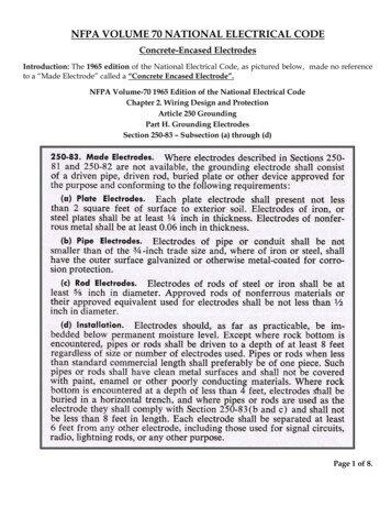
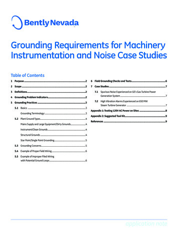
application noteStar Point/Single Point GroundingThe AC distribution diagram in Figure 2 shows that all thesubsystems in the plant – instrumentation, communication,computers and control, and AC power – are connected to a singlepoint ground system. This is known as “star point” grounding.Properly done, each subsystem ground is kept as short asreasonably possible and is connected to the star point atonly one point.Multiple paths to the ground plane from a subsystem should beavoided, as they can lead to errors within the subsystem. Thisoccurs because each path has inherently different resistanceand different resistances to ground produce, and by Ohm’s Law,different voltage potentials within the subsystemIf star point grounding is not used, increased vulnerability totransient surge damage, as well as less-reliable control systemoperation, can result. This can affect Bently Nevada monitoringsystem channels by causing errors in readings or causing channelsto enter into a NOT OK state. This can lead to false alarms and/orfailure to collect valuable machine waveform data. It may also beperceived as ground bounce, which causes some or all channelsin the monitor to vary in amplitude unrelated to machine activity,according to the changes on their reference connection.5.3 Grounding ConcernsAll grounds in a plant should be tied together at one point inthe plant. Wiring paths to that one point are separated accordingto the signal level carried by that ground wire.Ensure Proper Monitoring System Placement: Grounding canoften become an issue when the monitoring system is mounted atthe machine and away from the control room. Typically, running thegrounding conductor back to a clean reference is not consideredcost effective and plants may connect the monitoring systemground to the closest ground available, often a dirty ground.This is typically a machinery plant ground that has the potentialfor more transients and noise. The control room often has its owngrounding grid or mat that provides a low noise 0V reference point.Establish Effective Bonding: Most lightning damage toelectronic equipment occurs when a facility employs the useof multiple earthing references that are not intentionally, andeffectively, bonded together. Proper bonding between electrodesystems can reduce the voltage drops between them and establishan equipotential plane within the facility for enhanced personnelsafety. For example, lack of bonding between the electrical systemelectrode and the communications system electrode may resultin damage to modems, telephone answering machines, andother equipment during lightning and system fault conditions.A typical scenario employs a monitoring system in one buildingthat communicates with a DCS in another building.Building-to-building cabling introduces two risk areas. The firstrisk occurs when the two buildings are connected to differentelectrical power sources and have separate ground systems. Theseseparate ground systems can introduce ground loop currents intothe cabling with resulting noise and interference problems.The second risk is that susceptibility to interference or damagefrom lightning strikes, whether a cloud-to-cloud strike or aground strike, is greatly increased when signal or data linesexit a building. Within a building, the building’s Faraday cage,structural steel, metal siding, and so on, isolates and protectsthe equipment located within the shield. Cabling betweenbuildings penetrates the shield and becomes a source ofinterference or potential damage through the induced voltagein the cabling. Also, if a lightning strike actually hits one of thebuilding’s lightning protection systems, the ground potentialof that building can spike to a very high voltage causing a groundcurrent to flow to the other building.One approach to avoiding the problem is to interconnectthe ground grids of the two buildings and install the cabling ingrounded metal conduits between the two buildings. However,this is seldom done due to cost of installation.1 The use of fiberoptic cabling for data lines is an effective way to avoid theseproblems. However, signal lines on copper are used in thegreat majority of the installations. These lines can be protectedthrough the use of transient overvoltage protector isolators,optical or transformer, and appropriate installation of lightningarresters. The selection of properly rated surge protection,isolators, and/or lightning arresters is beyond the scope of thisApplication Note.Proper Shielding Techniques: A floating shield, not groundedat either end, can introduce as much noise in a system as ashield connected at both ends, creating a ground loop. In thisungrounded case, the shield can act as an antenna for switchingsignals, and these switching signals can capacitively couple tothe signal wires. This noise enters the monitor(s), affecting thevibration signal readings.A shield wire is to be treated in the same manner as the signalwire of a transducer. It needs to be insulated, isolated fromother conductors, and only connected to ground at a singlepoint at the monitor side. Experience has shown that impropershielding is likely the largest contributor to grounds loops in amonitoring system.The only time a grounding conductor (generally a green-insulatedwire, often with a yellow stripe) should carry significant currentis when a short circuit or lightning strike has happened, andtherefore in a fault condition.Since 2006, Bently Nevada cabinets may no longer connectthe shield of the field wiring to the monitor inputs. The shieldsare often tied to a ground bar just at the cable entry to thecabinet. This allows any noise on the shields to be drainedoff to the ground system with less potential effect on themonitoring system.Reduce Unwanted Coupling: Field-installed signal cablesshould be separated from power cables and conduits to thegreatest practical distance. This reduces unwanted couplingbetween the two circuits. To reduce noise coupling problemswhere one circuit crosses another, try to route the wires tocross at a right angle.1 Handbook of Electrical Installation, page 2355
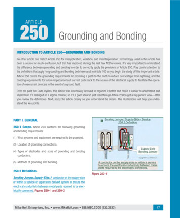
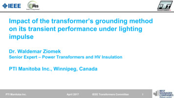
application note5.4 Example of Proper Field Wiring6 Field Grounding Checks and TestsNote: All grounding checks and tests should be performed byfollowing the guidelines in Bently Nevada reference document111M7647, Evaluation of Grounding Networks for InstrumentationSystems. The walk-down observations and data gathered whenfollowing the recommendations in 111M7647 should be recordedin a manner that allows it to be retained and placed in thesite report.Prior to following the tests in 111M7647 the following shouldbe performed:1.Download the 3500 rack information before testing.2.Walk down the installation from the monitor tothe transducer, inspecting each junction box orwire termination.Note each of the following:Figure 3: Bently Nevada Single Point GroundFigure 3 shows a typical transducer installation with the systemgrounded at a single point at the monitoring system.5.5 Example of Improper Filed Wiringwith Potential Ground LoopsFigure 4: Bently Nevada System with Potential Ground LoopsFigure 4 shows how multiple ground loops are formed when two ormore points in the monitoring system are connected to a groundat different places, and possibly different potentials. The voltagepotential causes an unintended current to flow in the ground loopcoupling noise into the system. This difference in reference voltagealso affects the vibration signal levels being measured. Currentflowing in the loop has both an AC and DC component. In addition,any loop acts as an inductor or antenna for magnetic fields andthese current loops will inductively couple to the signal path of themonitor. The size of the loop determines the frequency ranges towhich the system will be susceptible.6 The bonding of all metal surfaces to safety earth Where shields are terminated Where and how the signal commons are connected Where and how signal paths are connected. Any signs of loose, corroded, or poorly installedNote: Take pictures of terminals and connections, if possible.(Be sure to get permission from site management before takingpictures.)3.Identify the grounding connections of the 3500 rack.Locate where the cabinet ground is connected to theplant ground. Without disturbing the 3500 system,confirm the position of the Single-Point Ground Switch,located under the sheet metal cover, either above orbelow the power input connector on the 3500 PIM.The switch should be closed, unless the installationinvolves intrinsically safe wiring or a specifically designedexternal instrumentation ground connection. Draw adiagram of the grounding scheme and take pictures ofthe connections, wherever possible. Confirm that thepower feeding the 3500 rack PIM has a protective earthground wire (green, or green/yellow stripe). This wire mustbe connected to a 0V potential ground (protective earth).4.Follow the guidelines and perform the tests outlinedin 111M7647.5.When testing is complete again download the 3500configuration that was tested.
application note7 Case Studies7.1 Spurious Noise Experienced on GE’sGas Turbine Power Generation SystemIssue – The customer was experiencing random and spuriousvibration signals in the 3500 monitoring system used for machineprotection and management.System – GE’s eight 7FA gas turbines at the site were controlledby Mark* VI control systems. All vibration transducers werepowered from and connected to the Mark VI TVIB card. TVIB cardsprovided buffered output signals for each transducer that werethen connected to the 3500 monitoring system using a standardDB-25 cable for external terminations. The site used one 3500monitoring system for every two gas turbines. A 3500 monitoringsystem was located in the Packaged Electronic/Electrical ControlCompartment (PEECC) of each odd numbered gas turbine (units 1,3, 5 and 7). Each PEECC was placed 60 meters (180 feet) apart oncenter and grounded to the plant ground system.Discovery – When each gas turbine and PEECC was tied tothe overall plant ground system, a ground loop was created.Unit 1’s 3500 monitoring system and Mark VI system’s groundswere connected at the same point on the plant ground, butUnit 2’s Mark VI system was grounded 180 feet from unit 1.Connecting the transducer’s common from the buffered outputof the TVIB card to the 3500 monitoring system in unit 1 createdthe ground loop resulting in the spurious vibration signals.The 180 feet between the ground points of unit 1 and resultedin a voltage potential large enough to affect the vibrationchannel’s output.The Velomitor field wiring was eliminated by installing a spareVelomitor on Channel 5Y (one of the worst channels for spiking)on the external terminal block in the cabinet at the 3500 rack.Cycling of the lube oil relay resulted in no spike on channel 5Y.This testing indicated the close proximity of relays to the Velomitorfield wiring, and that the 3500 was not an issue. However, thefield wiring was a factor with the noise problem.Note: The following additional steps could have been performedto help isolate the issue and show that the Velomitor itself wasnot at fault. At the junction box, remove the Velomitor fromthe transducer field wiring and replace with a battery poweredfunction generator with a DC bias. Simulate the transducer usingan AC signal with DC bias (refer to the verification section in themanual for frequency and amplitude). Check to see if spiking isobserved in the measured signal at the 3500 rack.Solution – After consulting with the relay design engineer,a properly-sized diode was connected ‘backwards’ (reversebiased) across the relay coil. Note: This diode is not to besized or installed by Bently Nevada technicians; it must be thecustomer’s responsibility.Current flowing through a relay coil creates a magnetic fieldwhich collapses suddenly when the current is switched off. Thesudden collapse of the magnetic field induces a brief high voltageacross the relay coil that is very likely to be transmitted to othersignal wires. The protection diode allows the induced voltage todrive a brief current through the coil (and diode) so the magneticfield dies away quickly. This prevents the induced voltage frombecoming high, reduces some higher-frequency content, andreduces the likelihood of spikes being transmitted into to othernearby systems.Solution – Galvanic isolators were installed to isolate thecommons for each transducer signal for the even numberedunits 2, 4, 6, and 8.7.2 High Vibration Alarms Experiencedon 650 MW Steam Turbine GeneratorIssue – The customer was experiencing Velomitor channels onmultiple bearings entering alarm states. Proximity probes onthe bearings did not indicate a change in vibration levels. It wasdetermined that the alarms occurred when nearby relays, locatedabove and adjacent to the 3500 racks, were cycled to activate thelube oil system.Tests performed – The testing was started by cycling lube systemrelays and verified that 5 to 7 mil spikes were present in the3500 system at the time of the relay cycling. Because spiking wasconfirmed, the testing was continued.The installed Velomitor wiring was disconnected from the terminalsin the junction box. Spare Velomitor wiring that was available in thejunction box was connected to a Velomitor. The spare Velomitorwas not mounted to the turbine, but was located in the junctionbox. Cycling the lube oil relay again showed 5 to 7 mils of noise,and testing was continued.7
application noteAppendix 1: Testing 120V AC Poweron SitesAlways test the site power outlet socket if it is to be used topower line powered test equipment, such as the Bently NevadaADRE 408 DSPi. The socket must have the proper polarity have acorrectly installed ground wire, and be within the voltage limits.Customer sites have been found to have the line and neutralreversed in the power outlet, no ground wire installed, andneutral being used as a ground. This is not only against code,but is a safety hazard for the personnel operating the equipment.It can result in damaged equipment, or even a monitoring systemgoing into alarm when the test instrument is attached.Complete the followi
A primary purpose for grounding of electronic equipment is personal safety. A properly installed safety ground on electronic equipment allows faults to be cleared by the fast opening of circuit breakers or fuses and is no different than that of other equipment. Safe