Transcription
Static Testing of Batten Connectionsat University of Western AustraliaCTS Technical Report No 62December, 2015Cyclone Testing StationCollege of Science, Technology & EngineeringJames Cook UniversityQueensland, 4811, Australiawww. jcu.edu.au/cts
CYCLONE TESTING STATIONCOLLEGE OF SCIENCE, TECHNOLOGY & ENGINEERINGJAMES COOK UNIVERSITYTECHNICAL REPORT NO. 62Static Testing of Batten Connectionsat University of Western AustraliaByG.N. Boughton , D.J.Falck , Annie Vinh Nghi Duong3, Sarah Pham4, AndrewNguyen512December, 2015 Cyclone Testing Station, James Cook UniversityBibliography.ISBN 978-0-9942333-8-7ISSN 1058-8338Series: Technical report (James Cook University, Cyclone Testing Station); 62Notes: BibliographyStatic Testing of Batten Connections at University of Western AustraliaBoughton, Geoffrey Neville Investigation I. Falck, Debbie Joyce II. Duong, AnnieVinh Nghi III Pham, Sarah IV. Nguyen, Andrew V. James Cook University. CycloneTesting Station. VI. Title. (Series: Technical Report (James Cook University. CycloneTesting Station); no. 62.LIMITATIONS OF THE REPORTThe Cyclone Testing Station (CTS) has taken all reasonable steps and due care toensure that the information contained herein is correct at the time of publication. CTSexpressly exclude all liability for loss, damage or other consequences that may resultfrom the application of this report.This report may not be published except in full unless publication of an abstractincludes a statement directing the reader to the full report.1Adjunct Associate Professor, Cyclone Testing Station, James Cook University, TownsvilleCyclone Testing Station, James Cook University, Townsville3Undergraduate student, University of Western Australia, Perth4Undergraduate student, University of Western Australia, Perth5Undergraduate student, University of Western Australia, Perth22
Static Testing of Batten ConnectionsExecutiveSummaryThe project aimed to determine the uplift capacity and critical failure modes of fourbatten to MGP10 timber rafter connections now commonly used for sheet metal roofsin Perth houses:a) One 75 mm long bugle head screw through 35 mm thick timber battens;b) One 75 mm long bugle head screw through 45 mm thick timber battens;c) Two 40 mm long M5.5 Batten Zip screws through 40 mm steel top-hatbattens;d) Two 57 mm long hot-dipped galvanised nails through 40 mm steel top-hatbattens.AS 1684.2 only provides capacities for connection a). Some manufacturers andsuppliers specify connections b) and c). Connections b) to d) have been increasinglyused as batten to rafter or batten to truss connections in Perth in the past decade asmaterials and fixing techniques have changed.The results of static tests on these connections were analysed using AS/NZS 4063 andISO 12122.5. The capacities of the fasteners and connections were compared withvalues in AS 1720.1 and AS 1684.2. AS 1684.2 presents capacities for connection (a),but not for connections (b), (c) or (d). The results for the capacity of connection (a)were consistent with the values in Table 9.25 in AS 1684.2.The characteristic capacities of correctly driven connections into JD5 timber rafterswere as follows.a) One 75 mm long bugle head screw through 35 mm thick timber battens –3.5 kN;b) One 75 mm long bugle head screw through 45 mm thick timber battens –2.7 kN;c) Two 40 mm long M5.5 Batten Zip screws through 40 mm deep 0.55 mmBMT top-hat battens – 3.5 kN;d) Two 57 mm long hot-dipped galvanised nails through 40 mm deep 0.55 mmBMT top-hat battens – 0.74 kN.Notes:1. The results on timber battens are valid for batten widths of 70 mm or greater.2. Where fasteners are not correctly installed, capacities of some of the connections can besignificantly lower than the above values.Tests also showed that: There is no significant difference in connection capacity for 57 mm galvanisednails through four commonly available 40 mm deep 0.55 mm BMT top-hatbattens; and 75 mm smooth shank nails are inappropriate for fixing 40 mm deep 0.55 mmBMT top-hat battens in general and edge zones in all wind classifications.The tests confirmed that top-hat and timber battens should only be fixed inaccordance with either Standards, manufacturers’ recommendations or joint capacitiesjustified by appropriate test programs. The test program and investigations of damagefollowing wind events has reinforced that nails should not be used to fasten eithertimber or steel battens in all parts of the roof in any wind region.3
Static Testing of Batten ConnectionsTable of Contents1.Introduction . 71.1.Batten to rafter connections in practice . 71.2.Selecting batten to rafter fasteners from AS 1684 . 101.3.Over- and under-driven fasteners . 121.4.Previous studies . 131.4.1.Batten to rafter/truss capacities in AS 1684 . 131.4.2.Pull-through failures in batten to rafter/truss connections. 131.4.3.Withdrawal failures in batten to rafter/truss connections . 141.5.Aims of the project . 142.Laboratory tests . 152.1.Sampling. 152.1.1.Rafters for main test program . 152.1.2.Top-hat battens . 162.1.3.Timber battens . 162.2.Fabrication of specimens . 162.3.Testing equipment . 172.4.Preliminary testing . 182.4.1.Results . 192.5.Main test program . 212.5.1.Rafter density . 212.5.2.Bugle head screws into 35 mm thick timber battens . 222.5.3.Bugle head screws into 45 mm thick timber battens . 222.5.4.Screws into steel top-hat battens . 232.5.5.Nails into steel battens . 232.6.Analysis Methods . 242.6.1.Analysis Groups . 242.6.2.Characteristic values . 243.Tests on timber battens . 263.1.35 mm thick battens . 263.1.1.Centrally located screws . 273.1.2.Effect of edge distances . 313.2.45 mm thick battens . 323.2.1.Centrally located screws . 323.2.2.Effect of edge distances . 354
4.Tests on metal top-hat battens. 374.1.Screws through top-hat battens . 374.1.1.Test results . 374.1.2.Significance of results . 414.2.Nails through top-hat battens . 424.2.1.Significance of results . 464.2.2.75mm smooth shank nails . 474.3.Other connection configurations for top-hat battens . 475.Comparison of test characteristic values with design values . 485.1.Comparison with values in AS 1684 . 485.2.Comparison with values in AS 1720.1 . 495.2.1.Screws . 495.2.2.Nails . 496.Conclusions . 506.1.75 mm long bugle head screws through 35 mm thick timber battens . 506.2.75 mm long bugle head screws through 45 mm thick timber battens . 506.3.40 mm long M5.5 Batten Zip screws through 40 mm top-hat battens . 516.4.57 mm long hot-dipped galvanised nails through 40 mm top-hat battens . 517.References . 525
AcknowledgementsThe CTS acknowledges the valuable assistance and support given by; Mr Jim Waters, at the Civil Engineering Laboratory, UWA for assistance insetting up and conducting the tests; Mr Greg Flowers, Building Commission of WA for assistance with the nailingof all nailed specimens; Wespine Industries for the supply of all timber used to fabricate thespecimens; and Prof Guowei Ma for coordinating activities at UWA.6
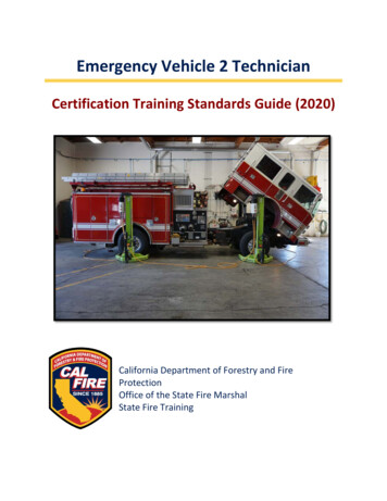
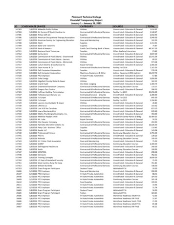
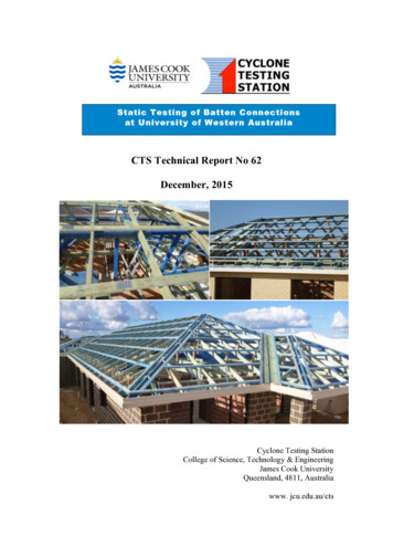
1. INTRODUCTION1.1.Batten to rafter connections in practiceFailure of batten to rafter or batten to truss connections have been identified ininvestigations of wind damage in Australia: Reardon et al (1999), Boughton (1999),Henderson and Leitch (2005), Henderson et al (2006), Boughton (2007), Boughton(2008), Leitch et al (2009), Boughton et al (2011), Henderson et al (2012), Boughton(2015) and Parackal (2015).These reports include damage to buildings in the cyclone prone wind regions (Windregions C and D) and the non-cyclone prone wind regions (Wind regions A and B).Design capacities of batten to rafter connections have been derived from productspecific tests and generic test programs on fasteners. However, construction practicesare changing and some commonly used connections are not supported by designvalues in AS 1684.2 (Standards Australia 2010a) or manufacturers’ information.Figure 1.1 shows a roof in wind region A that has metal top-hat battens fastened tosoftwood rafters with gun-driven nails, which are not included in manufacturers’recommendations for these connections.Figure 1.1 – Gun-driven nails used in metal battens (inset shows top view ofconnection).Failure of gun-driven nail connections between metal battens and softwood trusseswere observed by Boughton and Falck (2008) and are illustrated in Figure 1.2. In thiscase, some of the nails withdrew from the trusses and in other cases, the battens7
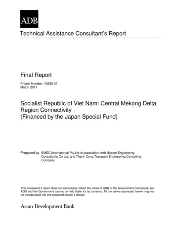
pulled over the nail heads near the edge of the roof, and progression of the failure toreroofing fasteners out of the battens near the ridge.Figure 1.2 – Failure of gun-driven nails connections between metal battens andtrusses. (Shading shows area of batten to truss failure.)Other roofs are constructed with timber battens. The 90 x 35 battens shown inFigure 1.3 can use connections selected directly from AS 1684.2 (Standards Australia2010a), as the assumed batten depth in the Standard is 38 mm. However, the battensin Figure 1.4 are 45 mm deep so the connectors do not have the same depth ofpenetration into the rafter assumed in AS 1684.2. Hence the capacity of theseconnections cannot be directly obtained from AS 1684.2.8
Figure 1.3 – connections between 35 mm thick battens and rafters.Figure 1.4 – connections between 45 mm thick battens and rafters. (Inset showsconnection detail.)Batten connections to trusses or to rafters have the same loads, the same load transfermechanism and the same capacity. In this report, batten to rafter and batten to trussconnections are both referred to as batten to rafter connections.Section 2 details three undergraduate research projects (Duong 2015), (Nguyen 2015)and (Pham 2015) to investigate the capacity of batten to rafter/truss connectionsobserved in contemporary construction in Perth WA. Some of these connections alsohave relevance for other parts of Australia. The investigation focused on: Nailed connections between steel battens and MGP10 rafters. 0.55 mm steel isusually used for the steel battens, and a number of different profiles areavailable. Two different types of gun-driven nails are commonly used forthese connections.9
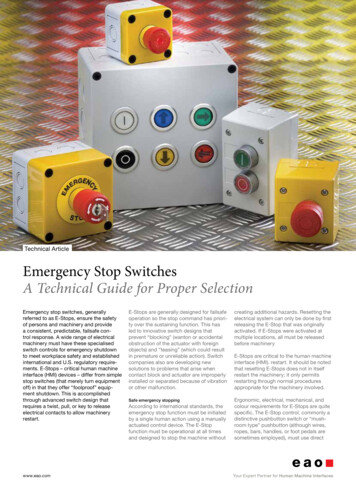
1.2.Screwed connections between top-hat battens and MGP10 rafters. Theseconnections are recommended by a batten manufacturer (Lysaght 2014).Screwed connections between 35 mm and 45 mm thick timber battens andMGP10 rafters. In many cases, 75 mm bugle head screws are used on both35 mm and 45 mm thick battens.Selecting batten to rafter fasteners from AS 1684Table 9.14 in AS 1684.2 (Standards Australia 2010a) provides the net uplift force(kN) on roof battens and is used to determine the loads fasteners must resistdepending on the following parameters: Wind Region A or B (use AS 1684.2), Wind Region C or D (use AS 1684.3); Wind classification; N1 to N4 for Wind Regions A and B; and C1 to C4 forWind Regions C and D, calculated using AS 4055 (Standards Australia 2012); Roof cladding material – tiles (including concrete or terracotta tiles) or metalsheet (or other lightweight cladding); Rafter spacing (mm) Batten spacing (mm) Roof zone – Edge (within 1200 mm of the perimeter of the roof, hips, ridges,fascias and barges) or General (all areas that are not edges).1.5Figure 1.5 – Evaluation of connection load from AS 1684.2 Table 9.14(Reproduced with permission from SAI Global Ltd under Licence 1505-c035)10
Figure 1.5 shows the uplift force on a batten to rafter connection for the followingexample: Wind Region A; Wind classification N2; Sheet roof; Rafter spacing 900 mm; Batten spacing 900 mm; Edge zoneThe uplift force for this example is 1.5 kN.The uplift force from Table 9.14 can be compared with the capacities of differenttypes of fasteners in Table 9.25. Table 9.25 shows uplift capacities of smooth shanknails, deformed shank nails, screws and framing anchors into unseasoned andseasoned timber battens of different cross-sections. In each case, the capacity is forconnections that have been correctly installed.Figure 1.6 shows that only Type 17 screws have sufficient capacity to resist the1.5 kN force on the fastener in the above example when fastened into JD5 timberrafters. Nails should not be used for JD5 batten to rafter/truss connections in edgezones.Figure 1.6 – Connection capacity for 35–38 mm thick battens from AS 1684.2 Table9.25 (Reproduced with permission from SAI Global Ltd under Licence 1505-c035.)11
AS 1684.2 (Standards Australia 2010a) provides deemed-to-satisfy solutionsreferenced by Volume 2 of the National Construction Code for many connections indomestic construction. However, it does not provide connection capacities for thefollowing connections observed in practice in WA: Nails into the flanges of steel battens; Screws into the flanges of steel battens; and Screws into 45 mm thick softwood battensSpecifications for structural work in domestic roofs often refer to AS 1684. Theconnections that are not included in AS 1684, or cannot be evaluated by calculationsfrom a referenced structural design manual such as AS 1720.1, must be regarded asalternative solutions. (Manufacturers have provided guidance that can be used forsome of these connections, but otherwise, the alternative solution must be supportedby documentation that the solution complies with the performance requirements of theNational Construction Code – most commonly by analysis or test data.) The testprogram presented in this report was designed to determine the characteristiccapacities for these connections.1.3.Over- and under-driven fastenersThe capacity of connections in AS 1684.2 (Standards Australia 2010a) assumes thatthe fasteners are correctly driven/installed and doesn’t consider variations ininstallation practices. However, observations of fasteners in roofs under constructionhave highlighted a range of installation practices: Under-driven fasteners – there is some space between the underside of thefastener head and the surface of the batten. Figure 1.7(a) shows an underdriven nail into a top-hat batten and Figure 1.7(b) shows an under-drivenscrew into a top-hat batten. Correctly-driven fasteners – the underside of the fastener is just in contact withthe surface of the batten. Over-driven fasteners – the fastener is driven further into the batten as shownin Figures 1.8(a), and Figure 1.8(b).(a) Nail into top hat batten(b) screw into top-hat battenFigure 1.7 –Under-driven fasteners on building sites– (Photo (a) Greg Flowers,Building Commission of WA and (b) Lex Sommerville)12
(a) deformed surface of batten(b) punched through a battenFigure 1.8 – Over-driven fasteners – (Photos Greg Flowers, Building Commissionof WA)1.4.Previous studiesThis section summarises some of the relevant test programs on batten to capacitiesinAS1684Testing by Reardon (1979a) and Reardon (1979b) provided the basis of many of thecapacities of batten to rafter connections given in AS 1684.2 (Standards Australia2010a). These tests and other tests on connections in Australia have been conducted tovarious versions of AS 1649 (Standards Australia 2001), and were originally reportedas basic working strengths. The limit state version of AS 1684 presents reanalyseddata as true characteristic values.1.4.2.Pull- sStudies by Prevatt et al. (2014) in the USA have shown that most failures in batten torafter connections have occurred due to poor nail installation; roof battens pullingover the nail heads (pull-through failures) or by nails withdrawing from their woodsupport (pull-out failures).Research conducted by Mahaarachchi and Mahendran (2002) suggest that prematurepull-through failures of light-gauge metal battens are associated with splitting aroundfastener holes, which may exacerbate roof structure damage during wind events.However, their study has yet to determine the criterion for the splitting of the fastenerhole.In timber to timber screwed connections, three possible failure modes are: withdrawalof the screw threads from the timber, pull-through of the screw head and steel failureof the screw shank (AS 1720.1 Standards Australia 2010b). AS 1720.1 recommendsthat designers consider pull-through failure for screws, although it does not explicitlyprovide an appropriate calculation m
CTS Technical Report No 62 December, 2015 Cyclone Testing Station College of Science, Technology & Engineering . Two 40 mm long M5.5 Batten Zip screws through 40 mm steel top-hat battens; d) Two 57 mm long hot-dipped galvanised na