Transcription
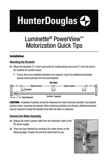
Luminette PowerView Motorization Quick TipsInstallationMounting the Brackets Mount the brackets 5" in from each jamb for inside/ceiling mount and 5" from the end ofthe headrail for outside mount. If more than two installation brackets are required, mount the additional bracket(s)spaced evenly between the two end brackets.Top ViewSpace EvenlySpace Evenly5"JambJamb5"BracketMotor/ " Gap Required58SofTrak HeadrailCAUTION: Installation brackets should be fastened into wood whenever possible. Use drywallanchors when mounting into drywall. When attaching brackets into drywall, additional bracketsmay be required to keep the headrail level after the fabric is attached.Remove the Motor Assembly Unplug the motor’s power cable from the extension cable to theDC power supply. There are two methods for removing the motor shown on thefollowing page. Choose the one that works best for you.PowerCableExtensionCable
INSTALLATION Method 1: This methodworks best when the fabrichas been removed from theheadrail.Insert the screwdriverinto the slot on the driveassembly. Twist aboutone-fourth turn to releasethe spring-latch, and pulldown gently on the motorassembly to separate. Method 2: This methodworks best when fabricis still installed on theheadrail.Insert a hex key into theside slot on the driveassembly (either front orback) to release the springlatch, then pull down gentlyon the motor assembly toseparate.2Twist toRelease
INSTALLATIONConnect PowerView ComponentsConnect the Motor Assembly Align the pins with the holes in the drive assembly. Press the motor up into the driveassembly until it clicks into place.IMPORTANT: If snapping the motor ontothe drive assembly seems difficult, graspthe lead carrier and pull the carriers slightlyaway from the motor, as shown at right.The motor should now snap in easily. If you remove the motor and need to reinstall it,check the drive assembly and make surethe tilt gear aligns with the arrows. If necessary, use a screwdriver to turn thetilt gear until it is aligned.Aligned Tilt Gear3
INSTALLATIONConnect the DC Power SupplyNOTE: When power is connected to the motor, a greenLED inside the manual control button housing will flash toindicate the sheer is ready for operation. Plug the power cable from the motor into theextension cable.Power CableMotorAssemblyExtension Cable Plug the other end of the extension cable into the DCpower supply. Secure the extension cable using the C-clipsprovided. Hide the cable behind the fabric, makingsure it does not impede operation. Space the C-clips approximately 15" apart along theextension cable, as shown. Plug the DC power supply into the power source.WARNING: Keep cables and small partsout of the reach of children. They can wrapcables around their necks and STRANGLE.They can also put small parts in their mouthsand CHOKE.15"MaximumWire RetainerDCPowerSupplyWARNING: Electric shock and/or a fire hazard may occur if not properly installed.4
OPERATIONTest Headrail Operation Use the manual control button on the motor to test the operation of the headrail, followingthe sequence below.1. Press and hold the manual control button for 6seconds. The sheer will move slightly.2. Release the manual control button. The sheerwill move to its fully open position to set theOPEN travel limit, then move to the fully closedposition to set the CLOSE travel limit. Next, thevanes will rotate counter-clockwise and thenclockwise to set the rotation limits. The sheerwill move slightly one more time to indicate thatthe travel limits have been set.ManualControlButtonNOTE: There could be up to an 8 second pause between the vanes tilting from counterclockwise to clockwise. Pressing the manual control button while the carriers are traversing or the pinion clips arerotating will stop the action. The next button press will traverse the carriers or rotate thepinion clips in the opposite direction.Using the PowerView RemoteFirst, activate the remote by pulling both plastic tabs from the back battery compartment.OPENGroup 2Group 1LEFT ARROWGroup 3Group 4Group 5Group 6Rotates vanes clockwiseRIGHT ARROWRotates vanes counter-clockwiseFavorite(Sheer/vane position)CLOSESTOP(Press and hold forprogramming mode)IMPORTANT: If you have more than one remote, see “Adding Additional Remote(s) to thePowerView Shade Network” in the PowerView Motorization Remote Control Guide.5
OPERATIONJoining a Sheer to a GroupIMPORTANT: The sheer will not operate using the remote until it has been joined to a group.1. Press and hold STOP for 4 seconds to put the remote in program mode. The lights on theremote will flash to indicate it is in program mode.2. Press the desired group number (1 – 6) on the remote. The light for the group number willflash to show it is selected.3. Press and hold the manual control button on the motor.4. While continuing to press the manual button, press OPEN on the remote. The sheer willmove slightly to indicate it has joined the group. Release the manual control button.5. Press and hold STOP for 4 seconds to exit program mode. The lights will stop flashing.Basic Operation1. To wake up the remote, simply pick it up or press STOP. The last group(s) selected will behighlighted and active.2. Press “all” or groups 1 – 6 to select the specific sheer(s) to operate. The group button(s) willlight to show they are selected.a. Multiple group buttons may be selected at a time.b. To deselect a group, press the group number again. The light for that group button will goout.3. Press CLOSE to traverse the selected sheer(s) closed, covering the opening.4. Press OPEN to traverse the selected sheer(s) open, uncovering the opening.5. Press STOP to stop the sheer’s movement anywhere along its travel.6. Press the right arrow to rotate the vanes counter-clockwise. (If the sheer is not alreadydrawn closed, pressing this button will close the sheer first and then rotate the vanes.)7. Press the left arrow to rotate the vanes clockwise. (If the sheer is not already drawn closed,pressing this button will close the sheer first and then rotate the vanes.)8. Press STOP to stop vane movement.9. Press FAVORITE to send the selected sheer(s) to a preset position. Refer to the PowerView Motorization Remote Control Guide on how to set a favorite position.6
OPERATIONFurther Operation and Programming InformationPowerView Pebble Remote and/or PowerView Surface Remote OperationFor information regarding operation and programming of the PowerView remote, refer to yourPowerView Motorization Remote Control Guide.PowerView Scene ControllerFor information regarding operation and programming of the PowerView Scene Controller, referto your PowerView Motorization Scene Controller Guide.PowerView App OperationThe PowerView Hub is required for PowerView App operation. For information regarding setupand operation using the PowerView App, refer to the online PowerView App Software Guide athunterdouglas.com/powerview/support.Resetting the SheerBasic ResetThe basic reset is used to set the sheer’s travel limits.1. Press and hold the manual control button for 6 seconds. The sheer will move slightly.2. Release the manual control button. The sheer will move to its fully open position to set theOPEN travel limit, then move to the fully closed position to set the CLOSE travel limit. Next, thevanes will rotate counter-clockwise and then clockwise to set the rotation limits. The sheerwill move slightly one more time to indicate that the travel limits have been set.Resetting Shade ProgrammingThis reset erases all programming from memory, including group assignments, preventing anyinput device from operating the sheer. Its primary use is during installation to correct group andnetwork assignments. This reset does not affect travel limits.1. Press and hold the manual control button for 12 seconds. The sheer will move slightly onceafter 6 seconds, then again after 12 seconds. Release the button.2. Refer to “Joining a Sheer to a Group” on page 6 to program the sheer to a group.7
2016 Hunter Douglas.All rights reserved. All trademarks used herein are the property of Hunter Douglas or their respective owners.1351036399/16
For information regarding operation and programming of the PowerView Scene Controller, refer to your PowerView Motorization Scene Controller Guide. PowerView App Operation The PowerView Hub is required for PowerView App operation. For information regarding setup and operation using the PowerView App, refer to the online PowerView App Software .