Transcription
PowerView Hub QUICK START GUIDE
When prompted, scan or type theAccessory Setup Code below.Table of ContentsKit Contents. . . . . . . . . . . . . . . . . . 3Connections. . . . . . . . . . . . . . . . . . 5Home Automation Integration . . . . . . .13Troubleshooting. . . . . . . . . . . . . . . 15 2018 Hunter Douglas. All rights reserved. All trademarks used hereinare the property of Hunter Douglas or their respective owners. 2/18
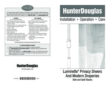
K IT CON T EN TSE.B.PowerView HubA.Wireless RouterD.C.RepeaterPower SupplyThe PowerView Hub interfaces with the PowerView App to allowcontrol of Hunter Douglas motorized window coverings from mobiledevices. The Hub can also integrate with home automation systemsvia IP or cloud-to-cloud integration.PowerView Hub USBPowerView RepeaterC. USB Power SupplyUSB Power Supply CableCable (Optional)A.D.B.E. EthernetNote: Download the PowerView App. The App is available for Apple iOS andAndroid mobile devices.Note: Do not expose the PowerView Hub to direct sunlight.Apple is a trademark of Apple Inc., registered in the U.S. and other countries.Android is a trademark of Google Inc.3
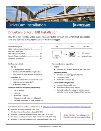
CON NEC T IONSPowerView HubWireless RouterRepeaterConnect Hub to Internet connected wireless router.Power SupplyConnect power to Hub.1. Connect one end of the USB power cable to the USB powersupply.2. Plug the USB power supply into an AC outlet or power strip.3. Plug the other end of the USB power cable into the power porton the back of the Hub.Note: During the boot-up process, the Hub’s LED will display different behavior tovisually communicate its status. Please refer to the PowerView LED Feedback charton page 14 of this guide for reference on different LED behavior. Do not interrupt theHub boot-up process until the Hub is ready to connect to a home network or join aPowerView Shade Network.Connect using an active WiFi network:Wait for the Hub LED to turn solid MAGENTA. This indicatesthe Hub is ready to connect to a WiFi network. Open thePowerView App on your mobile device and follow the on-screeninstructions to properly connect to an active WiFi network. Onceconnected to a WiFi network, the Hub will install a firmwareupdate and reboot. The Hub will blink AMBER when it is readyto join a PowerView Shade Network.Connect using an Ethernet cable (optional)Connect the Ethernet cable from the Hub to an open LAN port on your router.The Hub will install a firmware update and reboot. The Hub will blink AMBERwhen it is ready to join a PowerView Shade Network.Note: If connecting the Hub to the home network via Ethernet, connect theHub to the router, before connecting the Hub to power.5
CON NEC T IONSPairing your Hub with an existingPowerView Shade Network.If you have already established a PowerView Shade Networkbetween a PowerView Remote and PowerView shades, you shouldpair the Hub to the same network. To pair the Hub to the samenetwork, open the PowerView App and follow the prompts. TheHub LED will turn to solid BLUE, once the Hub has been paired tothe PowerView Shade Network.Distribute Repeater(s) as needed.Note: Do not expose the PowerView Repeater to direct sunlight.7
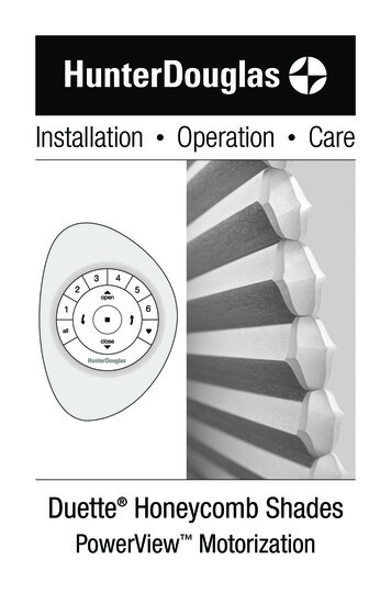
CON NEC T IONSTransfer your hub data (if needed).Test signal to Repeater(s).If you have a Gen 1 Hub (above left) on your PowerView ShadeNetwork, follow in-app instructions to transfer Hub data to thenew PowerView Hub.Press and hold the P button on the back of the PowerView Hub.The light on each Repeater should blink BLUE. If the Repeaterdoes not blink BLUE, move the Repeater closer to the Hub orpair the Repeater to the correct PowerView Shade Network.Other controls on the back of the Hub include the R buttonwhich power cycles the Hub and erases all Hub data whenpressed and held for 6 seconds.9
CON NEC T IONSConfiguring multiple Hubs on onePowerView Network (Optional).You’re ready to use the PowerView App.For more information about the setup and use of thePowerView App, please d/powerview-motorizationAfter a primary Hub has been paired to the PowerView Network, each subsequent Hub paired to the same networkwill automatically be configured as a secondary Hub (networkaccess point). Please follow in-app instructions to installsecondary Hubs.Note: The LED of secondary Hubs will display solid GREEN, once pairedto the PowerView Network.11
HOME AU TOM AT ION IN T EGR AT IONPowerView Motorization integrates with a varietyof leading third-party control systems and devices.To learn more about integration, please contactyour local Hunter Douglas dealer or d/powerview-motorization/works-with13
Blinking AQUAHub is booting up.Solid AMBERHub is updating firmware from the Internet.Blinking AMBERHub is ready to join a PowerView Shade Network.Solid BLUEConnected, normal operation.Solid MAGENTAHub is ready to be connected to a WiFiNetwork.Flashing BLUEHub is Transmitting command(s) to thePowerView Shade Network.BlankHub is not connected to power.Solid GREENHub is configured as a secondary Hub.Solid REDHub does not have an IP address.Problem: Cannot connect to the Hub with the PowerView App. Check for blinking AMBER, solid BLUE or solid MAGENTA on thefront of the Hub. (See LED Feedback chart above.) Check the connection between the Hub and wireless router andthat the router is operating properly. Check that the mobile device is on the same network aswireless router.U.S. Radio Frequency FCC ComplianceThis device complies with Part 15 of the FCC Rules. Operation is subject to the following two conditions:(1) This device may not cause harmful interference, and(2) This device must accept any interference received, including interference that may causeundesired operation.This equipment has been tested and found to comply with the limits for a Class B digital device,pursuant to Part 15 of the FCC Rules. These limits are designed to provide reasonable protectionagainst harmful interference in a residential installation. This equipment generates, uses and canradiate radio frequency energy and, if not installed and used in accordance with the instructions, maycause harmful interference to radio communications. However, there is no guarantee that interferencewill not occur in a particular installation. If this equipment does cause harmful interference to radioor television reception, which can be determined by turning the equipment off and on, the user isencouraged to try to correct the interference by one or more of the following measures: Reorient or relocate the receiving antenna. Increase the separation between the equipment and receiver. Connect the equipment into an outlet on a circuit different from that to which the receiver is connected. Consult the dealer or an experienced radio/TV technician for help.Any changes or modifications not expressly approved by the party responsible for compliance could voidthe user’s authority to operate the equipment.This equipment complies with FCC radiation exposure limits set forth for an uncontrolled environmentand meets the FCC radio frequency (RF) Exposure Guidelines. This equipment should be installedand operated keeping the radiator at least 20cm or more away from person’s body. RF Exposurerequirements are met when installed in mobile equipment. This module cannot be installed in portableequipment without further testing and a change to FCC’s grant of authorization. Contact Murataregarding portable applications.T ROUBLESHOOT INGPowerView LED FeedbackIndustry CanadaUnder Industry Canada regulations, this radio transmitter may only operate using an antenna of a typeand maximum (or lesser) gain approved for the transmitter by Industry Canada. To reduce potentialradio interference to other users, the antenna type and its gain should be so chosen that the equivalentisotropically radiated power (e.i.r.p.) is not more than that necessary for successful communication.This device complies with Industry Canada licence-exempt RSS standard(s). Operation is subject to thefollowing two conditions: (1) this device may not cause interference, and (2) this device must accept anyinterference, including interference that may cause undesired operation of the device.Class B Digital Device NoticeThis Class B digital apparatus complies with Canadian ICES-003, RSS-Gen and RSS-210.CAN ICES-3 (B)/NMB-3(B)This equipment complies with IC radiation exposure limits set forth for an uncontrolled environmentand meets RSS-102 of the IC radio frequency (RF) Exposure rules. This equipment should be installedand operated keeping the radiator at least 20cm or more away from person’s body.European ConformityWe, the undersigned,Hunter Douglas Window FashionsOne Duette Way, Broomfield, CO 80020, USAHunter Douglas Europe B.V.Piekstraat 2, 3071 EL Rotterdam, The Netherlandscertify and declare under our sole responsibility that the PowerView Hub conforms with the essentialrequirements of the EMC directive 2004/108/EC and R&TTE directive 1999/5/EC.A copy of the original declaration of conformity may be found atwww.hunterdouglas.com/RFcertifications.15
Hunter Douglas Window Fashions One Duette Way, Broomfield, CO 80020, USA Hunter Douglas Europe B.V. Piekstraat 2, 3071 EL Rotterdam, The Netherlands certify and declare under our sole responsibility that the PowerView Hub conforms with the essential requirements of the EMC directive 2004/108/EC and R&TTE directive 1999/5/EC.