Transcription
AN910PICmicro Device Programming: What You AlwaysWanted to Know (But Didn’t Know Who to Ask)Author:Eric SomervilleMicrochip Technology Inc.INTRODUCTIONThere is a lot material out there about microcontrollerprogramming. Most of it focuses on the software side ofthings – orthogonal instruction sets, code optimization,high-level language programming tricks and tweaks inassembler environments, even taking advantage of adevice’s peculiarities to make it do what you want. Thisis, of course, a very good thing, as microcontrollers endup doing more complex tasks in more sophisticatedapplications, the ability to write elegant code becomesmore and more valuable.What doesn’t get mentioned as often is the last key partof the process: actually getting that elegant code intothe microcontroller itself. The author still rememberswell his first experience, in the days before Microchipeven existed, of trying to piece together severalhardware specifications in order to figure out how theprogramming process was supposed to work. True,device programming is a vital step, but it doesn’talways get the attention it deserves.That brings us to the point of this application note. Formore than a decade, Microchip has published a lot ofinformation about programming its 8-bit microcontrollers. There is now so much information outthere, in fact, that it’s sometimes hard for engineersand technicians who are unfamiliar with Microchipproducts to know where to start. The purpose of thispaper is to provide the entry point for information onprogramming Microchip’s 8-bit microcontrollers. Whilewe can’t cover every programming specification indetail, we can give you a good idea of how the processworks and show you what to look for in a specification.We’ll also touch briefly on how in-system programmability can affect an application’s design and finish withother programming and diagnostic innovations thatmake applications more reliable. 2004 Microchip Technology Inc.THE BASICSIf you’ve had previous experience with programmingmicrocontrollers, you’re already familiar with the basicissue: a microcontroller in an embedded application isnot a computer. There is no convenient built-in GUI forloading a program. You can’t just insert a tiny floppy inthe side and press any pin to continue. Instead, youuse a hardware protocol to get the device’s attentionand present it with the intended program in an unambiguous fashion. If the designers have done their jobcorrectly, the device will interpret the incoming data andwrite it to memory exactly as you intended.For the vast majority of PICmicro devices, the protocolis known as In-Circuit Serial Programming (betterknow as ICSP ). Since Microchip introduced it in theearly 1990s, serial programming methods of some formhave become the standard for in-system programmingfor most microcontroller manufacturers. The protocolallows programming functions to be multiplexed withexisting device pins, avoiding the need of tying upprecious I/O real estate with ports that might only beused occasionally, if at all.Although the exact implementation varies from onePICmicro family of devices to another, the basic ICSPprotocol remains the same. When the device is supplied with a normal power supply and a specific voltageon the Master Clear (MCLR) pin, a state machine builtinto the core architecture takes control. It accepts serialdata and clock on two of the port pins and writes theinformation to the appropriate target memory space.The entire process is controlled by a set of specialcommands that accompany the serial data stream.That sounds simple, doesn’t it? In principle, the wholesystem can be reduced to those basic concepts. Thereare, of course, lots of details that must be observed forthings to work correctly and many of those differdepending on the particular device family. It is thosedetails that we will discuss here.Keep in mind if you’re using one of Microchip’s deviceprogrammers, such as PRO MATE II or a programmeroffered by one of Microchip’s approved third partypartners, that all of these details will be handled for youautomatically. It is those cases where the ICSP operation is used as it was named – that is, programmingthe microcontroller in the system – that knowing howthe process works will help you to understand theissues and make the application work for you.DS00910A-page 1
AN910The ICSP Hardware ProtocolGenerally speaking, all PICmicro microcontrollers areplaced in Serial Programming mode by doing thesethree things in sequence:1.2.3.Applying the appropriate power source andground (VDD and VSS) to the device;Raising the voltage on the MCLR pin to the programming voltage level (in general, around13V), while at the same time:Pulling the two designated I/O port pins to logiclow and holding them there.A few details are worth mentioning here. First, applyingVDD and VSS means all digital and analog supply andground pins, including AVDD and AVSS, not just thosepins that are convenient. This is usually stated clearlyin the first page or two of each programming specification, which is a separate document from the data sheet.If it isn’t, it is safe to assume that the device requires it.The programming voltage applied to MCLR, alsoknown as VPP, varies with device architecture. Thevoltage level (referred to throughout the literature as“VIHH”) can be specified as a fixed range for olderEPROM devices, or as an offset of VDD in Flashdevices. A safe generalization for all PICmicro microcontrollers is a VIHH of 13V; however, it is always bestto check the particular device’s programming specification first for its particular values. This is why all programming specifications call for a well regulatedvoltage source with a resolution of 0.25V.Besides the level of VIHH, there is a requirement for thetransition time to that level. The text in some specifications may be non-specific, but there is almost always adefined and very short interval. There is a very goodreason for the brevity: the device may begin to executewhatever is in its program memory if VDD is applied forsufficient time before VPP reaches VIHH. Although thisis not an issue with OTP parts, which are shipped blankand will only perform NOP instructions, it may causeconcerns if a Flash device is being reprogrammedwhile in the application.Premature code execution is primarily a concern withapplications that use a fast-starting RC oscillator or thedevice’s internal RC oscillator; however, it could be anissue for any oscillator type if the VPP rise time is sufficiently long. In fact, some earlier devices are evenmore explicit, requiring that VIHH already be on MCLRbefore VDD is provided to the part. This is good practicefor any application that uses an RC oscillator andwhere external Master Clear functionality is disabled. Inall cases, it means that VPP not only requires a regulated supply, but an output with adequate drive behindit to bring the level up sufficiently fast. This isparticularly important where the circuit uses addedcapacitance or strong pull-up resistors.DS00910A-page 2There’s also the matter of the ports. Depending on thedevice, the two programming pins are usually multiplexed with functions on PORTB, most often RB6 andRB7 and are designated “PGC” (Program Clock) and“PGD” (Program Data). For really low pin count deviceswith only one I/O port (like those in the PIC12 family),the programming pins are GP0 and GP1. If there’s anydoubt as to which pins are associated with serial programming, refer to the pinout diagram in the devicedata sheet or programming specification.As a final clarification on ports: some newer PICmicrodevices have a MCLR pin that can be turned into something else. Specifically, the pin (usually GP3, RA5 orRE3, depending on the pin count) can function as aninput-only port when the MCLRE configuration bit isset; in these cases, external Master Clear functionalityis disabled. Even if the pin is configured as a port,however, it can still function as the trigger for ICSPoperation. Applying VPP to this pin when it is configuredas a digital port still invokes the ICSP protocol asbefore, provided the other conditions are met.When all conditions are met for the appropriate setupinterval, the on-board serial programming statemachine takes control. The device enters an Idle state,where the CPU and all the peripherals are unclockedand then waits for a clock signal to appear on the PGCpin to start the programming process. The programming voltage on MCLR is also used by EPROM-baseddevices (and a few earlier Flash devices) to charge theprogram memory array and get it ready for theincoming data.Programming itself is a synchronous process, startingas soon as a clock train is applied to PGC; there is nolatency. This is very important to note, as the state ofPGD on each and every falling edge of PGC is latchedand interpreted as a data bit. If the data stream gets alate start, the net effect is to left-shift the incoming dataor commands, with accordingly bad results. Starting thedata stream before the program clock is ready will endup right-shifting your data, which is just as bad.PGC also controls the way that data and commandsare clocked in and out. Unlike some serial protocolswith a constant clock train, the ICSP protocol differentiates data items by using intervals between short pulsetrains. For a command to receive data, as an example,some number of pulses are sent to clock in the accompanying data on PGD. PGC is then held low for aninterval longer than one clock cycle; then PGC ispulsed a certain number of times to clock in more data.These longer “PGC held low” intervals mark the boundaries between commands; they are used by the statemachine to complete the current command andprepare for the next. The intervals themselves vary,based on their purpose and the particular programmingalgorithm used by a device family and are spelled outin the programming specifications. 2004 Microchip Technology Inc.
AN910Timely introduction of the data stream is not the onlyconcern. The setup and hold times for data on PGDmust also fall within certain specifications to actually berecognized as valid data (that is to say, a valid logic ‘1’or ‘0’). There are also minimum intervals that must beobserved in separating programming commands fromtheir accompanying data and commands from eachTABLE 1:other. All of these intervals vary from family to familyand are detailed in the appropriate programmingspecification.Besides those we’ve just discussed, there are manymore specified voltage levels and timing intervals inICSP operation. The most commonly used terms aredefined in Tables 1 and 2.COMMON DC CHARACTERISTIC DEFINITIONS IN MICROCHIPPROGRAMMING pply voltage for device during programmingSome Flash specifications may give multiplevalues or ranges under VDD, depending on theoperation (program/verify, erase, bulk erase, etc.).Regardless of the application’s operating range,the device’s VDD must be held in the appropriaterange during the programming operation.VDDPSupply voltage for device during programmingUsually specified for OTP devices (Flash devicesspecify one or more VDD ranges; see above).Regardless of the application’s operating range,the microcontroller’s VDD must be held in thisrange during programming.VDDVSupply voltage during verifyUsually a range specified for OTP devices. Mostalgorithms require verification at the minimum andmaximum ends of the range to ensure properprogramming.Voltage on MCLR to enable high-voltage ICSP programmingFor most devices, this serves as the hardwaretrigger and the source for charging the programmemory array. Specified as a range.Voltage on MCLR and/or PGM to enablesingle-supply ICSP programmingThis is the secondary trigger and the voltagesource for charging the program memory array insingle-supply ICSP programming.VIH(VIH1)Input high-level (logic ‘1’) limit on PGC:PGDDefines the lower limit of what will be recognizedas a logic ‘1’. This term may be used in somespecifications in the same sense as VIHL. It is notnecessarily the same value. “VIH1” is the earlierusage.VIL(VIL1)Input low-level (logic ‘0’) limit on PGC:PGDDefines the upper limit of what will be recognizedas a logic ‘0’. “VIL1” is the earlier usage.IDDCurrent requirement for MCLR/VPP duringprogrammingNot always specified; more likely to be seen onOTP devices.IDDPCurrent requirement for device during programmingTotal current drawn during programming for all VDDpins; expressed as a typical or maximum.CIOLoading capacitance on I/O pinsGeneral requirement for all devices for meeting ACspecifications listed in their data sheets. Inprogramming, applies primarily to PGC and PGD.VIHH(VIHH1)VIHLNote 1:This list represents the most commonly defined DC specifications for ICSP programming and is notexhaustive. Specifications not listed here are defined in the programming specification where they occur. 2004 Microchip Technology Inc.DS00910A-page 3
AN910TABLE 2:COMMON AC TIMING PARAMETER DEFINITIONS IN MICROCHIPPROGRAMMING imum rise time for MCLR (Vss to VIHH) to(tVHHR and enter Programming modeTR)TFCommentsTR is more commonly used with OTP devices.MCLR must rise to VPP faster than this value.Maximum fall time for MCLR (VIHH to VSS)MCLR must return to VSS faster than this value.TSET0PGC:PGD pattern setup time (minimum timefrom start of logic ‘0’ to start of MCLR rise toVIHH)Definition for Flash devices.TSET1Minimum setup (rise) time for PGD beforePGC falling edgeTHLD0Minimum time to hold PGC and PGD low afterMCLR rises to VIHH to enter Programming modeTHLD1Minimum hold time for PGD beforePGC falling edgeDefines the time that PGD must be in a particularstate to be clocked in as valid.Tdly1(TDLY1(4))Minimum required time between PGD not beingdriven and next rising edge of PGCReflects the minimum time between adjacentcommands, or a data payload and the nextcommand from PGD’s point of view.Tdly2(TDLY2(4))Command separation interval (minimum timefrom falling edge of clock to next rising edge)Also reflects the difference between commands, orbetween commands and data payload, from PGC’spoint of view. PGC is held low during this interval.TDLY1 is always smaller than TDLY2.Tdly3(TDLY3(4))Data out valid time (minimum time from risingclock edge to valid data out)Defines the time that PGC must be high before PGDis read as valid.Erase cycle time (Flash memory only)May be specified in several ways depending on theerase operation (program memory, entire device,etc.).Programming cycle time (Flash memory only)May be specified in several ways depending on theprogramming operation (program-with-erase,program only, low-voltage program, etc.).Programming pulse width (EPROM memoryonly)Represents the interval between “BeginProgramming” and “End Programming” commands,where PGC must be held low. Although alwaysrequired, this interval is not explicitly defined in manyspecifications.TERATPROGTPWNote 1:2:3:4:This list represents the most commonly defined AC specifications for ICSP programming and is notexhaustive. Specifications not listed here are defined in the programming specification where they occur.Specifications exclusive to Parallel Programming modes are not included.The most common typographic representations are shown with alternate versions in parentheses. Exceptwhere noted, these symbols correspond to equivalent intervals between timing waveforms for all ICSPprogramming specifications.Many programming specifications label diagrams by parameter numbers (intervals labelled “P1”, “P2”,etc.), which are cross-referenced to the listed symbols. The correspondence between parameter numbersand symbols may vary between the specifications for different families. For consistency, it is better todescribe AC timing intervals in terms of the listed symbols and not parameter numbers.The most common usages are indicated. All of the TDLY intervals (with the variant representation) haveslightly different definitions in PIC17CXXX and PIC18CXXX. Also, TDLY3 is not defined for PIC18CXXXdevices; it is called “TVALID” instead.DS00910A-page 4 2004 Microchip Technology Inc.
AN910SINGLE-SUPPLY PROGRAMMINGThe Building Blocks of ProgrammingAn additional advantage of many devices with Flashprogram memory is that they are capable of in-systemprogramming without the regulated 13V source. Thismethod is known as single-supply programming, sinceonly VDD is required. Historically, Microchip hasreferred to this mode as low-voltage programming tocontrast it with standard ICSP operation and its“high-voltage” VPP requirement. Using this methoddoes involve some trade-offs, however.Although we’ve established a protocol for getting theinformation into the part, we still have to successfullywrite it to the proper memory space. Regardless of thePICmicro device that we’re programming, there areseveral steps we must always perform.Single-supply ICSP programming uses an additionalprogramming pin, labeled PGM, with the other pinsrequired by the normal (High-Voltage) mode. The programming voltage for the memory array is generatedby an internal charge pump when normal operatingvoltage (VDD) is placed on the pin. When the PGC andPGD pins are held to logic low at the same time as VDDis applied to both PGM and MCLR, the microcontrollerenters Programming mode.The normal Programming mode is still available tousers and can be used just as before. In fact, except forthe method of entering the Single-Supply mode, allother programming specifications remain the same.The primary difference is the elimination of the regulated 13V supply requirement, which can be a distinctadvantage in adding in-circuit and in-the-fieldreprogrammability to an application.The Single-Supply mode is available as an option,which is controlled by the configuration bit, LVP. Thedefault, unprogrammed state of this bit ( 1) enablessingle-supply programming. Since PGC, PGD andPGM are typically multiplexed with port pins (generallyRB3/RB5, RB6 and RB7), this means that the I/Ofunction of these pins is lost when single-supply ICSPprogramming is enabled. This also means that whensingle-supply programming is used, additional precautions must be taken to ensure that PGM is alwayspulled down to a logic low level, in order to preventinadvertent entry into Programming mode.For those users who don’t need single-supply programming, this mode can be easily disabled by clearing theLVP bit ( 0). However, this can only be done in thestandard ICSP mode. Since most applications don’trequire single-supply programming, a good practice inusing devices with this capability is to perform the initialprogramming in normal mode, setting the LVP bit to ‘0’in the process. If singly-supply programming becomesnecessary later on, it can be restored by setting the bit(again, using normal ICSP mode) back to ‘1’.Single-supply ICSP programming is available on selectPICmicro devices with Flash program memory. In mostcases, devices that implement self-programmable memory (see page 15) also implement the single-supplyoption. 2004 Microchip Technology Inc.1.2.3.4.Load the data. This involves giving a commandthat unambiguously tells the device, “The stufffollowing me is a word of data. Get ready torecord it.” The state machine knows that a specified number of bits after the command are serialdata to be serially shifted into a buffer (LSb first).Write the data to memory. This commandsays, “Take the contents of that buffer and put ithere.” Just where “here” is may be defined bythe command itself (for example, programmemory or data EEPROM), or may include aprogram counter by reference. It could also bebased on what data was loaded in the lastcommand.Read back the data from memory. This is notsaying “Give me a copy of what was just in thebuffer”, but rather, “Give me a copy of what isnow in the location that you just wrote to”. Thatmay seem like a minor difference, but it can, infact, be significant; it works with the next step tomake sure that data was written successfully.Verify the data against the source. This is anexternal process that compares the dataoriginally sent to the part with what the part hasjust read from the programmed memorylocation. This not only ensures that the datawasn’t garbled in transmission, but also verifiesthat the individual memory cells have beenunambiguously set to the correct binary value.Parts of this process are actually handled by the programming state machine inside the microcontroller.Most of it, however, is handled by some agency outsideof the device. This is usually some combination ofhardware and software that “decides” what sequence iscorrect for a particular device, queues up the necessary commands and data and toggles the appropriatevoltages and signals on the right pins in the rightsequence.As we’ve already mentioned, there are a number ofdevice programmers that will take care of everything foryou – as long as the microcontroller can be placed ina programmer socket or connected to an externaldevice. It is when you need to debug an assembly lineprogramming process, or add in-system field programming to a Microchip-based design, that understandingthe details of actual programming specificationsbecomes necessary.DS00910A-page 5
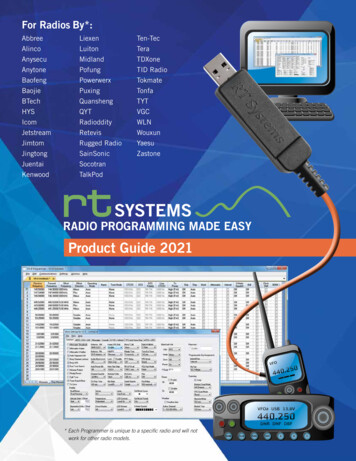
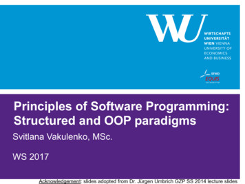
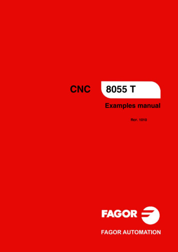
AN910Managing the Process:The Programming CommandsNow that we know how the information gets into thedevice, the next question is, “How does the deviceknow what to do with the information?” The answer issimple: programming is controlled by a completelydifferent set of commands that are distinct from thenormal PICmicro instruction sets.In broad terms, there are two versions of the programming command set: one for the mid-range and previousarchitectures and one for the enhanced PIC18 architecture. How these commands are used to carry out theprogramming building blocks will be covered later.PICmicro devices, up to the mid-range level with 12-bitand 14-bit instruction words (from PIC12 throughPIC16), all use a common set of 6-bit instructions. Forbrevity, we’ll refer to this version of the protocol as the“PIC16 method” or the “mid-range method”. In practicalterms, this programming method works directly onmemory locations under state machine control. Data isloaded, programmed and read back by separatecommands. The program counter is incremented withits own explicit command.Commands are issued by cycling PGC for 6 clocks;data is sent over PGD at the same time. A command isfollowed by an interval where PGC is held low, todelimit the command from what follows. If the command is used to move data, such as “Load” and “Read”,it is followed by 16 cycles of PGC for the data payload;during this interval, data is clocked in (for a Load), orclocked out (for a Read). As previously mentioned,data on PGD is clocked in on each falling edge of PGC;data being read out is clocked on the rising edge ofPGC, starting with the second clock pulse. Since theactual data is only 12 or 14 bits long (depending on thedevice), the payload is padded with ‘0’s at the leadingand trailing ends as needed to get a total of 16 bits.During a mid-range method programming cycle, only6-bit programming commands may be executed;instructions from the core instruction set are notavailable. The timing for a typical mid-range methodcommand is shown in Figure 1.In contrast, PIC18 devices do not have separate programming commands in the same sense as themid-range method. Instead, the architecture of thisfamily incorporates instructions (Table Read and TableWrite) that allow direct access to the program memory.To enhance this feature for ICSP operation, PIC18devices use a 4-bit command “shorthand” that actuallyimplements the existing Table Read and Table Writeinstructions. An additional NOP command allows theuser to execute other instructions for the core instruction set under ICSP control; data following a NOP isinterpreted as an instruction rather than data and isexecuted accordingly.DS00910A-page 6Note:The only instructions that can’t be executed using the NOP are Table Reads andTable Writes. Attempting this will disruptthe internal timing of the ICSP statemachine. Table Reads and Table Writescan only be done in ICSP operation usingtheir 4-bit command versions.Commands are issued in a manner similar to themid-range method; in this case, PGC is cycled 4 timesfor each command, followed by a delimiting interval.When the command has a data payload, PGC isclocked 16 times as data is being loaded, or 8 times asdata is being read out. (The difference is because program memory is written as a two-byte word, but read assingle bytes.) As with the mid-range method, data isclocked in on the falling edge of PGC. Data being readout, however, is also clocked out on the falling edge,starting with the first clock pulse.By combining sequences of Table Read, Table Writeand Move Register commands, all of the explicit commands in the PIC16 programming command set can beduplicated. This may seem inefficient until you considerthat the Table Read and Table Write commands canalso implicitly increment or decrement the TablePointer. These instructions also eliminate the need forseparate commands to load and write data, whichmakes the overall process faster than its PIC16counterpart. The timing for a typical PIC18 4-bitcommand is shown in Figure 2.It is also important to note that, no matter which command method is used, information is sent to and fromthe device during programming with the Least Significant bit first. This applies to programming commands,as well as any data being loaded or read back.A summary of the 6-bit and 4-bit ICSP commands ispresented in Table 3.Note:In programming specifications for PIC18devices, the terms “SCLK” and “SDATA” areused interchangeably for “PGC” and “PGD”,respectively. The latter designations are thepreferred usages.Don’t confuse “SCLK” and “SDATA” with“SCK” and “SDA”, which are names for themultiplexed clock and data pins of theSynchronous Serial Port peripheral.Attempting to program the device withthese pins will result in a programmingfailure, at the very least. 2004 Microchip Technology Inc.
AN910FIGURE 1:EXAMPLE OF A 6-BIT “LOAD PROGRAM MEMORY” COMMAND (PIC16F87XA)VIHHMCLR1 µs minTSET012346 TDLY2 t bitXTSET1stp bitTSET1TDLY11 µs minTHLD1THLD1}}}}100 ns min100 ns minProgram/Verify Test ModeResetFIGURE 2:EXAMPLE OF A 4-BIT PIC18 COMMAND SEQUENCE(TABLE WRITE/POST-INCREMENT WITH DATA IN 12131415162134P5AP5P4P3RB7/PGD(Data)101100004-bit Command00010004C16-bit Data Payload111100nnnn3Fetch Next 4-bit CommandRB7 StateRB7 Input 2004 Microchip Technology Inc.DS00910A-page 7
AN910TABLE 3:OVERVIEW OF 6-BIT AND 4-BIT PROGRAMMING COMMAND SETS6-bit Command Set (PIC12 through PIC16)InstructionLoad Configuration WordLoad Program DataOpcode (MSb.LSb)0(1)(1)0(1)Read Program Data0Increment Address0(1)Data Payload Format0(1)00000(1)00100(1)01000(1)0110Begin Programming orBegin Erase/Programming Cycle(2)001000Begin Programming Only Cycle(3)011000(5)(5)Load Data Memory(4)xx0011Read Data Memory(4)x(5)x(5)0101Bulk Erase Program Memory(3)x(5)x(5)1001x(5)x(5)1011End Programming0(1)0(1)1110Chip Erase(9)x(5)11111Bulk Erase DataMemory(4)(7,8)0, (data (0:13)), 0N/A0, (data(0:7)), 0000000N/A4-bit Command Set (PIC18)InstructionOpcode (MSb.LSb)Data Payload FormatForced NOP (core instruction follows)0000Shift Out Value of TABLAT(10)0010Table Read, don’t change pointer1000Table Read, post-increment pointer1001Table Read, post-decrement pointer1010Table Read, pre-increment pointer1011Table Write, don’t change pointer1100Table Write, post-increment pointer(11)1101Table Write, post-decrementpointer(11)1110Table Write, pre-increment pointer orstart programming(12)1111data (0:15)Legend: x Don’t care.Note 1: These values must be ‘0’ for OTP devices, but are “don’t-care” for most Flash devices. Refer to theprogramming specification for a particular device for exceptions.2: Implemented as “Begin Programming” for OTP devices and “Begin Erase/Program” for Flash devices.3: Implemented for Flash devices only. Some devices implement this as an externally timed write requiringan “End Programming” command; other devices do not implement it at all. Refer to the programmingspecification of a particular device for specific information.4: Implemented only for Flash devices with data EEPROM. The trailing pad of the data payload is seven ‘0’s.5: These values must be ‘0’ for some Flash devices. Refer to the programming specification for a particulardevice for the specific requirement.6: Implemented for Flash devices only.7: Implemented for OTP devices and some Flash devices. A very few devices implement this command as‘xx1010’.8: Rare Flash devices use ‘x10111’ to terminate externally timed programming.9: Implemented for rare Flash devices to erase everything on the device, including data EEPROM. Deviceswithout data EEPROM may use this term for what other devices refer to as Bulk Program Erase.10: Implemented on PIC18F devices only.11: For PIC18 OTP devices, the increment/decrement is 1; for PIC18F devices, it is 2.12: For PIC18 OTP devices, the command pre-increments the Table Pointer before performing the TableWrite. For PIC18F devices, the command initiates the timed programming cycle.DS00910A-page 8 2004 Microchip Technology Inc.
AN910READING A PROGRAMMINGSPECIFICATIONWhen you approach PICmicro device programming forthe first time, you may see a huge array ofdocuments – lots and lots of documents, with eachsubfamily of devices getting its own specification.When you find the one for your device of interest, you’llfind pages and pages of text, diagrams, code examples, timing and voltage specifications, all of it callingfor your attention. You may ask, why are there so manyspecifications? And where do I start?To begin with, Microchip makes many different types ofmicrocontrollers. Although everything up to the PIC18devices is based
PICmicro family of devices to another, the basic ICSP protocol remains the same. When the device is sup-plied with a normal power supply and a specific voltage on the Master Clear (MCLR) pin, a state machine built into the core architecture takes control. It accepts serial data and clock on two of the port pins and writes the