Transcription
mmmmaking education easiermmatrixmultimediaPICmicro Microcontrollerdevelopment board data sheetContents12345678910111213General informationFeaturesBlock schematicGeneral descriptionProgramming softwareTesting the development boardSupported PICmicro microcontrollersPin out details and bus connectionsLiquid crystal displayOn-board analogue sensorsExternal analogue sensorsCircuitsExternal digital sensorsCopyright (C) 2001 Matrix Multimedia media.co.ukPIC and PICmicro are registered trademarks of Arizona Microchip Inc. www.microchip.com
1General informationThe Matrix PICmicro microcontroller (MCU) development board isdesigned to form part of the World’s best solution for learning PICmicroprogramming.The remit of all Matrix products is to Make Education Easier. Thisphilosophy is fulfilled with this development board in two ways:Makes it easier to teach and learn PICmicro programming!!!Designed for educational use3 CD ROM based resources in assembly, C, and flow chart programming areavailableFree download software, PPP, provides seamless send and verify functionsMakes it easier to develop PICmicro projects!!!!!!!Supports low cost Flash-programmable PICmicro devicesFully featured displays - 13 individual LEDs, quad 7-segment display and LCDdisplaySupports PICmicro microcontrollers with A/D convertersOn-board sensorsA comprehensive range of external analogue and digital sensors are available forproject workFully protected expansion bus for project workAll inputs and outputs available on screw terminal connectors for easy connectionThree courses and programming systems compatible with this productare available on CD ROM:
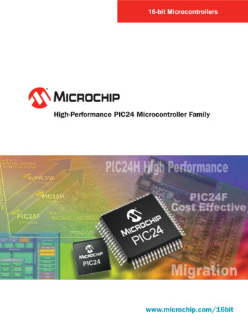
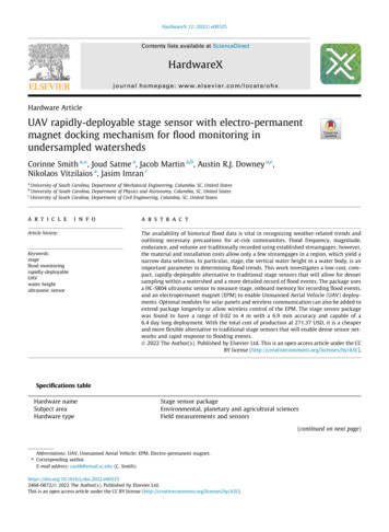
2FeaturesThis page describes the features of the development board:21m25 matrixmultimedia0VPort A I/OA3A2Port B I/O0V1514B649D1B3LCD display - 2 line 16 V3Ana23RA3DigS36J1422LA3LA4SA4SA3B5B418S116B7MCU device at a timeS4A1A0S5RV2!WARNING!mm m fit only one PICmicro 19A410 SB1SB0LA2SA2Port ASB611SB5SB2Port B1 Power connector - unregulated 12V supply via PSU jack (positive outer) or 2 terminalscrew connector2 25 way D-type - connects board to PC parallel port via standard 25 way cable3 Expansion bus - 40 way expansion bus suitable for IDC cable connection4 Port B I/O - connections for all port B PICmicro I/O5 Audio output - connects via coupling capacitor to port A0 for simple tone generation6 Digital external sensor - connects to selected Port B pins for use with Verniermotion/distance detector and light gate7 Quad 7-segment display - dual 7- seg. displays in 2 banks8 7-segment display switch - switches power to 7-segment displays.9 LCD display - 2 line 16 character quasi-intelligent alphanumeric display which isprogrammed via 4 serial pins on port B of the PICmicro10 LCD contrast potentiometer - controls contrast on LCD display11 Port A/B switches and indicators - Individual switches connect 5V to port A/B inputs.Indicators show status when I/O pins are configured as outputs12 Port A analogue/digital selection jumpers.13 PICmicro turned pin DIL sockets - DIL sockets for 8, 18, 28 and 40 pin PICmicros caution: fit only one PICmicro at one time. PIC16F84 fitted as standard. Note that if you arefrequently changing the PICmicro device you are using it would be wise to fit additional turnedpin sockets / a ZIF socket to the board to preserve the life of your sockets and yourPICmicros.14 Reset switch - Resets PICmicro MCU15 RC clock speed potentiometer varies clock speed when RC switch is selected16 RC clock speed switch - controls clock speed (fast or slow) when RC switch is selected17 Clock crystal / RC switch - controls whether the board runs off a 3.2768MHz crystal orfrom an on-board RC circuit.18 Program indicator light - indicates when PICmicro is being programmed.19 Port A I/O - connections for all port A PICmicro input and outputs20 LCD display switch - switches power to LCD display.21 Potentiometer - part of the sensors system - simulates a varying analogue voltage on portA1 for testing code during program development.22 Light sensor - part of sensors system - on-board light sensor23 External analogue sensor - allows connection of one of a range of analogue sensors fromtemperature sensors to heart rate monitors.24 5V output connector - not normally fitted.
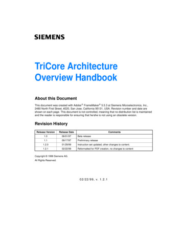
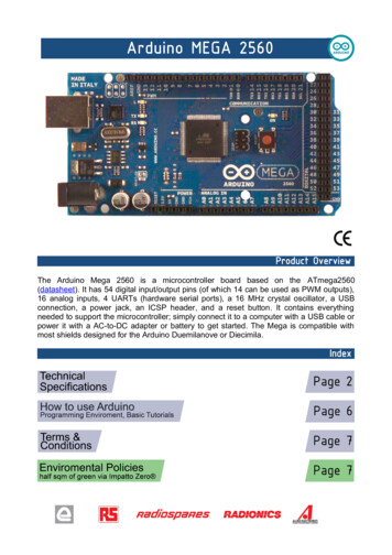
3Block schematicS225 Pin ‘D’ ConnectorRCUnregulated supplyXtalslowfast2 wayscrewterm6S42.1mmDC JackProgrammingRCspeedRead/Write LEDClock circuit2-ve veReset Switch [S1]regulation2audioout12V5V0V2 [RB6, RB7]1 [RA0]External I/O Port Port Bpush switchesJ14 link blockpush switchesSA3External I/O Port B8RA3DigAnaSA48 Pin18 Pin28 Pin40 Pin[RB0 - RB7]analogue inputsPort A5[RA0 - RA4]PIC devicesSB740SB6SB5SB4SB3SB2SB1SB0SA0expansion busLEDsLEDsLB7 LB6 LB5 LB4 LB3 LB2 LB1 LB0LA4 LA3 LA2 LA1 LA06 [RB0 - RB5]1 [RA4]digitalVernier sensorLCD display - 2 line 16 character4[RA0 - RA3]ononquad 7 seg displayS5S3offContrastoffRV2Default switch/jumper conditionsS2 RC [RC mode]S4 slow [RC speed]S3 off [7 seg displays]S5 off [LCD display]J14 DigitalNote that J14 jumpers should always remain on the digital position when using a PIC16F84as it does not have an analogue capability.
4General descriptionThe PICmicro development board is designed primarily for learning how toprogram PICmicro applications. It also allows a wide range of PICmicromicrocontrollers to be programmed and the ‘seamless’ nature of theprogramming software supplied with the product (the PICmicro ParallelProgrammer or simply ‘PPP’) makes it suitable for the development of arange of PICmicro projects.The board is optimised for use with a PIC16F84 from Arizona Microchipwhich has a number of features:!!!Crystal or RC operation2 ports: Port A - 5 pins and Port B - 8 pins. i.e.: 13 programmable pins which can allbe used as inputs and outputs.Flash programmable - up to 1,000,000 programming cyclesWhilst the 16F84 has no analogue capability and is not the most functionalPICmicro available it has been selected for use with this development boardfor a number of reasons:!!!!It is a low cost device - suitable for project work in schoolsIt has been widely used in third party projects and there is a wide body of codeavailable for itIt has a relatively simple internal topologyIt is electrically re-programmableA full list of other PICmicros that the board can support is listed below.The board has been designed to allow students with little or no experienceof embedded microcontroller programming to be able to produce highlyfunctional designs in as short a time as possible. With this in mind we haveincluded switches on each input/output pin, a quad 7-segment display, a 2line 16 character alphanumeric display, a choice of crystal or RC oscillator,simple on-board analogue sensor (light) and sensor simulator(potentiometer) and the ability to interface the board to a host of externalsensors from Vernier Inc. of the USA.Full tutorials in programming the PIC16F84 in both assembly code and in Care available. These sets of tutorials are available on CD ROM and requireno other software - all compilers and development environments areincluded on the CDs themselves.Schematic description - please refer to block schematicThe board is based on a flexible topology that allows the inputs and outputsto be used in a number of ways depending on switch settings on the board.This flexibility means that students will, as they use additional features,need to be aware of how a single input-output (I/O) pin can be used for anumber of functions dictated by the circuitry attached to it. This is explainedin the Circuits section of this document.
The architecture of the board is split into two main buses - the port A busand the port B bus. Each line on each bus can be used as either an input oras an output. The connectors and displays on the board are all wired inparallel on the PIC pins for convenience but clearly connecting more thanone device to one pin will result in conflict: students will need to be madeaware of this.Port A busUnder normal operation all of the jumper links in the J14 link block are in theDigital position. This means that the Port A I/O pins are routed to the pushswitches and LEDs. The actual circuit is described in the Circuits section.Note that operating the push switches whilst a voltage is connected to port Avia the external screw terminals is not advisable as it will result inunpredictable results. Port A screw terminal connectors are fed to the pinson the PICmicro via 150 ohm resistors which provide short circuit protection.With J14 links in the Digital position port A is routed to its push switches(SA0 to SA4), LEDs, digital Vernier sensor I/O, and the quad 7-segmentdisplay. Bits RA0, RA1, RA2 and RA3 are used for the common anodes ofeach of the four 7-segment displays. RA0 is used for tone generation via thejack plug, and bit RA2 is used for the digital Vernier sensor input.With J14 links in the Analogue position port A is switched to the analoguesensor section of the board. This means that RA0 is connected to the onboard light sensor, RA1 is connected to the potentiometer wiper for sensorsimulation, and bit RA2 is connected to the external analogue Verniersensor connector.With J14 links in the Analogue position you should be aware that on-boardswitches and LEDs will not operate.If you want to use the external port A screw terminal connectors foranalogue inputs you should remove the links off J14 altogether.Port B BusPort B I/O pins are routed to its push switches (SB0 to SB7), the LEDs (LB0to LB7), the quad 7-segment displays, the LCD display and the screwterminal connectors. Note that the screw terminal connectors are fed to thepins on the PICmicro via 150ohm resistors which provide short circuitprotection. However operating the push switches whilst a voltage isconnected to Port B is not advisable as it will result in unpredictable results.Port B is also used for programming the PICmicro - the PPP software usedfor programming the PICmicro will automatically take over pins required forprogramming, verifying and resetting the PICmicro on the board.Clock circuitryDuring early stages of learning PICmicro programming students often wanteach clock cycle to be large (1 second) so that they can see code executingvery slowly (flashing LEDs don’t simply become ’less bright’ LEDs) . ThePIC16F84 supports this feature by having an RC mode of operation. Use of
RC mode also reduces component count and cost for small projects.S2 selects between RC mode and Crystal mode.S4 selects fast or slow operation when RC mode is selected.RV1 adjusts the speed of the clock within a range dictated by S4.Power supply circuitThe board is normally operated from an unregulated DC supply of 12V. Thisallows full operation including programming.The board can be operated from 8 1.5V AA cells if required but students willlose the ability to program the PICmicro which requires just over 12V.The optional power supply shipped with the PICmicro board (UK versions)is rated at a maximum of 500mA. You should be aware that the board couldconsume more current than this if you are connecting several externaldevices on the external I/O.If you do require the on-board PICmicro to drive several external outputsyou may wish to fit a heat sink to the 7805 regulator. The layout of theprinted circuit board should easily accommodate this.DisplaysThe LCD display is connected to Port B I/O. The LCD display is turned onby switch S5.The quad 7-segment display is connected to both Port A and Port B. Port Bis used to control each of the 8 segments (7 for the main character and 1for the full stop). Port A bits 0 to 3 are used to select each of the 4characters.The quad 7-segment display is turned on by switch S3. Note that turning onthe display will affect the operation of Port B I/O and when using the quad7-segment displays it is recommended that you do not use Port B for anyother purposes. Under certain circumstances you will notice that segmentsof the quad 7-segment display may be lit up very dimly by Port A/Boperation even when S3 is in the off position. This is a feature of the lowcost driver circuitry and is unavoidable.
5Programming softwareThe PICmicro Parallel Programmer [PPP] allows an assembled program tobe sent to virtually any PICmicro microcontroller on the PICmicroDevelopment board. Both raw OBJ files generated by TASM, and ASCIIencoded HEX files generated by MPASM can be sent using PPP. PPP usesa simple user interface which is explained in the accompanying help file.PPP is supplied free with the development board. Features include:!!!!!!Operates with the latest parallel port standardsHEX and OBJ file compatibleRange of Xtal and RC operation modesReads content of any non-protected PICmicroConfirms each byte of code sentBit selection on configuration word available for advanced usersMinimum requirements!Pentium 100MHz, Parallel printer port, 1 Megabyte of hard drive space, 16Megabytesof RAM, Windows 95/98/ME/NT/2000/XPInstallationInsert the floppy disk supplied with the PICmicro development board,navigate to the floppy drive on the target computer and execute the installfile named “PPP install”. A shortcut will be added to the desktop and to theStart menu.[Administrator Privileges are required to install on Windows NT/2000]Setup!!Insert the power supply into a wall outlet, then connect to the PICmicro board.Connect the parallel cable to both the computer’s parallel port and to the PICmicroboard.ConfigurationBefore sending a program to the PICmicro board, PPP should be set upcorrectly. Start the PPP program then on the toolbar click on the “Configurethe PICmicro” icon [Ctrl - C]. In the configuration box -!!!!!Select chip typeSelect the oscillator type [XT if using the on-board crystal, or RC if using the on-boardresistor and capacitor]Select the correct port for the parallel cable [on most computers the default is 0x378]Leave both the watchdog timer and the power-up timer unchecked unless theprogram to be sent requires them.Enable code protection, if the contents of the PIC should not be read, only after it hasbeen programmed.[N.B. The configuration word can be altered manually - please refer to PICmicro datasheets for details.]SendingTo open a file click on the “Open a PICmicro code file” icon on the toolbar[Ctrl - O], navigate to the file to be sent. To send the file click on the “Sendthe code to the PICmicro” icon on the toolbar [Ctrl - P]. As the code is sentto the PICmicro board the Program LED turns on. When all the code hasbeen sent the LED turns off. If verification has been selected the LED turnson, whilst the code is being read. After all the code has been read the LEDturns off and PPP informs the user if all the code had been sent correctly.
6Testing the development boardWhen you first receive your development board you should check itsoperation. There are two parts to this - checking that the hardware workscorrectly and checking that you can download programs into the PIC16F84that is supplied with the board.Your board will be supplied with a PIC16F84 that already has a test programin it. This simple test program simply flashes the I/O port LEDs in turn.Simply connect the power supply to the development board: if the Port Aand B LEDs make a ‘knight rider’ effect then you know that your PICmicro isup and running and your basic circuitry is operational.Note that the switch settings for this core program are:S2 - RC positionS4 - slowJ14 - Digital positionS5 - LCD display offS3 7-seg display offYou can now test the board can communicate with the PC. To do this loadPPP (see previous page) and send the file BLANK.HEX to the PICmicro.Further instructions are given in the PPP help file. This will clear yourPICmicro.Your development board should now be inactive - basically there will be noprogram in the PIC16F84.Next send the program TUTTEST.HEX to the PICmicro. Once this iscomplete then your board should be running the same ‘knight rider’ programas before.You now know that your development board is up and running correctly.Further test programs for this development board are available from our website: www.matrixmultimedia.co.uk.You will find the program TEST40.HEX the factory test routine - particularly useful. This operates on a PIC16F870and is used in the factory to do a complete and thorough test of yourhardware during manufacture.
Supported PICmicro microcontrollersThe PPP program has been designed to work with the most populardevices in circulation at the time of developing the PICmicro microcontrollerdevelopment board (November 2001). These are listed below.Exhaustive tests have been carried out with selected devices from each ofthe main PICmicro families. The chips we have used in these tests areshown in red. All the devices listed below should function without difficulty. Ifyou do experience any problems then please contactsupport@matrixmultimedia.co.uk.Please also check www.matrixmultimedia.co.uk for updated versions of thePPP software and a more up-to-date list of supported devices.Supported PIC DevicesDigital Only8 Pin 18 Pin 28 Pin 40 6F87116F87416F877
8 Pin out details and bus connectionsBroadly speaking the ranges of PICmicro devices are designed to beupwards compatible: the pin functions on an 18-pin device are available ona 28-pin device and a 40-pin device. This can be seen from the followinginformation taken from the Microchip product selector 37RA4/T0CKI/CMP2236GP1/AN1/VrefVpp/RA5/THV/ SO/T1CKIRB2/TX/CK811RB5RB3/CCP1910RB4/PGMNote that GP0 maps to RB7GP1 maps to RB6GP2/AN2 maps / /AN2/Vrl/Vref-437RB4/KBI0RA3/AN3/Vrh/Vref 524RB3/PGM/CCP2RA3/AN3/Vrh/Vref P6/PC16RC5/SDO/D C6/TX/CKRC2/CCP11724RC5/SKO/D RC3/SCK/SCL1823RC4/SDI/SDA/D-RD0/PSP0/C1IN 192022RD3/PSP3/C2IN-21RD2/PSP2/C2IN OSC1/CLKIRC1/T1OS/CCP2IRD1/PSP1/C1IN-RB1/INT1
This has allowed us to wire the 8, 18, 28, and 40 pin devices in parallel onthe development board. Whilst the board is optimised for a PIC16F84 ( an18 pin device) it can also therefore be used for almost any PICmicro. Thefollowing table shows you the pin comparison chart for all devices. You willfind this chart a useful reference tool.Pin Comparison ChartBus Name 18 Pin 8 Pin 28 Pin 40 PinVpp/ MCLR 44113220141Vdd318 198Vss513169OSC1210153OSC214522RA0/AN0 1733RA1/AN1 RE0/AN59RE1/AN610RE3/AN7Expansion busThe pin connections on the expansion bus exactly mirror the pin numberingon the 40 pin DIL socket. The best way of connecting devices to theexpansion bus is by using an IDC cable.
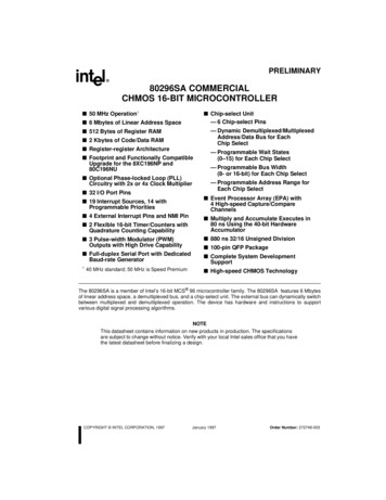
9Liquid Crystal DisplayThe LCD is a 16 character x 2 lines module. Internally it is 40 characters x 2lines. Line 1 ranges from H’00’ to H’27’ and Line 2 ranges from H’40’ toH’67’.01 2 3 4 5 6 7 8 9 A B C D E F 10 11 12 13 14 15 16 17 18 19 1A 1B 1C 1D 1E 1F 20 21 22 23 24 25 26 2740 41 42 43 44 45 46 47 48 49 4A 4B 4C 4D 4E 4F 50 51 52 53 54 55 56 57 58 59 5A 5B 5C 5D 5E 5F 60 61 62 63 64 65 66 67Internal [40x2]Display Window [16x2]The LCD Module uses a Samsung KS0066U controller, which is similar tothe Hitachi HD44780 controller.The PICmicro board uses port B [B0 to B5] to program the LCD, as shownin the circuit diagram below. When the PICmicro board is turned on, datacan only be sent to it after 30ms, this is the time taken for the LCD toinitialize [as it clears all the RAM and sets up the Entry Mode].Port BB5 B0 B1 B2 B3 B4LCDDatabusEnableLCD Module5VContrastcontrol4k7LCD Block DiagramTo send a command to the LCD, data must be sent in two steps, the MSBfollowed by the LSB [byte is data on B0 to B3]. As each byte is sent to theLCD, B5 must be go high then low, for the LCD to acknowledge the byte.After the second byte has been acknowledged the LCD executes thecommand. The PICmicro board must wait for at least the length of theexecution time for that command, before the next command can be sent. Atiming diagram of this process is shown below.LCD BusyTimingDiagramB5B0 - B3MSBLSBMSBLSBThe first command to be sent to the LCD must be ‘Function Set’ [to setupthe LCD], this is usually followed by ‘Display Control’ and then ‘ClearDisplay’. According to ‘Entry Mode Set’ after each character is sent to theLCD, the position of the cursor changes [by default it is incremented].
LCD Instruction try nTimeDescriptionB4 B3 B2 B1 B00 0 0 0 Clear all display data. Set DDRAM address to 0. Move cursor to0 0 0 1 home position. Entry mode set to increment.0 0 0 0 Set DDRAM address to 0. Move cursor to home position.1.53 ms1.53 ms0 0 1 X0 0 0 0 Sets cursor move direction (I/D), specifies to shift the display (S).0 1 I/D SH These operations are performed during data read/write.39 us0 0 0 0 D is Display ON/OFF bit. C is Cursor ON/OFF bit.1 D C B B is Blink Cursor ON/OFF bit.0 0 0 1 Sets cursor-move or display-shift (S/C), shift direction (R/L).0S/CR/L X X DDRAM contents remains unchanged.39 us39 usFunctionSet00 0 1 0 Configuration data for setting up LCD. [Send First]Set CGRAMAddress00 1 A5 A4 Sets the CGRAM address. CGRAM data is sent and receivedA3 A2 A1 A0 after this setting.39 usSet DDRAMAddress01 A6 A5 A4 Sets the DDRAM address. DDRAM data is sent and receivedA3 A2 A1 A0 after this setting.39 usWrite Datato RAM139 us1 0 X XD7 D6 D5 D4Writes data to CGRAM or DDRAM.43 usD3 D2 D1 D0DDRAM is Display Data RAMDDRAM address is location of cursorCGRAM is Character Generator RAMX is Don t CareLCD Character SetHintplease look at our website for examples of codethat shows how toprogram the 7-segmentdisplay. (TEST40.ASMfactory test routine.)Bit NameI/DSHDCBS/CR/L0Decrement cursor positionNo display shiftDisplay offCursor offCursor blink offMove cursorShift left1Increment cursor positionDisplay shiftDisplay onCursor onCursor blink onShift displayShift right
10On-board analogue sensorsTo use an analogue sensor, the PICmicro board must manually be set to analogue modeand an analogue-capable PIC must be used. Whilst in analogue mode certain port Apins [A0/RA0,A1/RA1 etc] are able to convert an analogue signal to an 8 or 10 bit digitalsignal, using the on-board A to D converter inside the PICmicro device.Please refer to Microchip data sheets for more details.The analogue sensors are not normally connected to the PICmicro pins but are switchedon to them under the control of the jumpers on J14.Several analogue sensors are relevant:LDRA compact cadmium sulphide light dependent resistor is soldered onto the developmentboard. When J14 link RA0 is in the ‘analogue’ position it is connected to A0 on thePICmicro microcontroller. The resistance of this device reduces as light falling on to itincreases.5VTechnical specificationDark resistance1M OhmResistance @ 10 Lux 10-20k Ohm100 Lux 2-4k OhmPeak spectral response 540 nm15kA0PotentiometerMost passive sensors are based on a simple potential divider circuit. In order to get yourcode up and running as simply as possible it is therefore useful to have a simulation ofthe full operation range (0V to 5V) that a sensor might provide. This function is simulatedby a simple 5k preset potentiometer (RV3) with a series 10k resistor, which produces avoltage in the range of 0V to 5V on RA1. Note that J14 / 1 will need to be in theanalogue position to use this circuit.5VA15k10kExternal analogue sensorIn addition to the above the link J14 / 3 also switches a voltage from a range of externalactive sensors onto pin A3/RA3 of the PICmicro microcontroller. These active sensorsare designed specifically for educational purposes by Vernier Inc. of the USA. Details ofthese sensors are given below.
11External analogue sensorsA host of external analogue sensors can be attached to the PICmicro board,the output from the sensor goes to RA3.Light SensorThe sensor uses a Hamamatsu S1133 silicon photodiode. It produces avoltage which is proportional to light intensity. The spectral responseapproximates the response of the human Eye.The switch on the box is used to select the range. If the voltage from thesensor reaches the 2.8-volt maximum, you need to switch to a lesssensitive range. If the voltage is very small or 0, you need to select a moresensitive range.!!!The 0-600 lux range is selected when the switch is in the middle position. This is themost sensitive range, and is useful for low levels of illumination. The voltage from thesensor will change 1volt/200 lux.The 0-6000 lux range is selected when the switch is in the up position. This is a goodgeneral purpose range for indoor light levels. The voltage changes 1volt/2219 lux.The 0-150,000 lux range is selected when the switch is in the down position. This isused mainly for measurements in sunlight. The voltage changes 1volt/50,000 lux.MicrophoneThe microphone uses an electret microphone that has a frequency response coveringessentially the range of the human ear [20Hz - 16kHz]. An op-amp circuit amplifies andsends the signal centred at 2.5 volts. You will need to make sure the sound level is in thecorrect range to produce good wave patterns. If the sound is too loud, the wave patternwill be clipped. Move the microphone further from the sound source, or turn down thevolume of the sound.
Stainless steel temperature probeThis uses a 20 k ohm NTC thermistor to measure temperatures in the range of -25 C to125 C. Accuracy is 0.2 C at 0 C and 0.5 C at 100 C. The thermistor is a variableresistor whose resistance decreases non linearly with increasing temperature. The best-fitapproximation to this nonlinear characteristic is the Steinhart-Hart equation. At 25 C, theresistance is approximately 4.3% per C. The Response time after 11 s is 95% of fullreading, after 18 s 98%, and after 300 s is 100%.pH SensorThe pH Sensor will produce a voltage of 1.75 volts in a pH 7 buffer. The voltage willincrease by about 0.25 volts for every pH number decrease. The voltage will decrease byabout 0.25 volts/pH number as the pH increases. The pH Sensor is designed to makemeasurements in the pH range of 0 to 14 within a temperature range of 5 C to 80 C andthe 90% of the final reading is attained within 1 second.Using analogue sensorsTo make use of the analogue sensors you will need a PICmicro that has anin-built Analogue to Digital converter (ADC). The PICmicro shipped with theboard - the PIC16F84 - does not have an ADC built in. Examples ofPICmicros that do have A/D converters built in are:PIC16F710PIC16F8744 off 8 bit ADC channels4 off 10 bit ADC channelsThere are two steps in using an analogue sensor:1. Reading the value of the voltage at the ADC input2. Understanding how this relates to the analogue parameter beingmeasured.Reading the value of the voltage at the ADC input is simply a matter ofsetting up your ADC and you should refer to the Microchip datasheet forfurther instructions on this advanced feature.Relating the resulting hex value to the actual analogue parameter should bepossible with the information supplied above and a small amount ofmathematics. The results should be of a suitable accuracy for the majority ofapplications.If you require higher accuracy you will need to calibrate your sensor relatethe hex values read in by the PICmicro to exact known light levels, pH levelsetc. Calibrating the sensors to a high level of accuracy will invariably involveusing a known piece of test equipment that is already calibrated.
12CircuitsSwitches and LED’sPort A [A0 - A4] and Port B [B0 - B7] on the PIC can be directly used for I/O on thePICmicro board, using onboard switches and LED’s. The basic circuit which allows thesame PICmicro connector I/O pin to be used as either an input or an output is as follows:5V390RPICmicroSA0 - SA4SB0 - SB7RA0 - RA4RB0 - RB7590R4k7LA0 - LA4LB0 - LB7Multiple connectionsThe development board allows several variations on this basic circuit by the inclusion ofswitches and links on the board. There are a number of variations of this as follows:RA0 to RA3RA0 to RA3 are used to select which 7-segment display is used, are used for analogueinputs and are also connected to the screw terminals. The actual circuit used here is:5VExternal I/O Port A390RPICmicro150RJ14 link block1kRA0 - RA3Common anode connection590ROn-boardanalogue sectionLA0 - LA3a [B0]4k7f[B5]g [B6]b[B1]e[B4]d [B3]c[B2]dp [B7]J14 allows students to effectively switch RA0 to RA3 to analogue or digitalcircuitry. Removing the link altogether will connect RA0 to
13 PICmicro turned pin DIL sockets - DIL sockets for 8, 18, 28 and 40 pin PICmicros - caution: fit only one PICmicro at one time. PIC16F84 fitted as standard. . Whilst the 16F84 has no analogue capability and is not the most functional PICmicro available it has been selected for use with this development board