Transcription
11/29/2005 - 8:00 am - 11:30 am Room:Americas Seminar [Lab] (Dolphin)Walt Disney World Swan and Dolphin ResortOrlando, FloridaAutodesk Revit Building Family Editor - From theBeginningStephen Stafford - Stafford Consulting Servicesand David Conant; Cyril Verley (Assistant); Scott Davis (Assistant)BD21-1L Intended to compliment Course BD35-2 "Take Your Family to the Next Level", this lab will guide youthrough the process of creating a complete door family. Along the way you'll gain valuable insight intothis powerful feature of Autodesk Revit. By the end of class, not only will you will have a door familythat you can use right away, you'll know how to do it again. You'll feel empowered to apply whatyou've learned to make the content you need, when you need it. Special guest speaker David Conantwill be on hand to provide his unique insight into the family editor and several well known Revit guru'swill provide lab assistance.About the Speaker:Steve supports the implementation of Revit for Wimberly Allison Tong & Goo in Newport Beach, CA.He has been using and loving Autodesk Revit even before Autodesk purchased it. He bringsknowledge, passion, and energy to everything he does. Prior to joining WAT&G he was a CADadministrator and also did design work for firms in New York state.steve stafford@cox.netDavid was the first architect to work for Revit Technology Corp. He helped develop the initialdesign of the Autodesk Revit software has been guiding its development for more than 6 years.He brings to that task his professional experience as a registered architect involved in design,design computing management, and CAD training. David has been a well received speaker atAutodesk University for several years. Prior to working with Revit, David worked as an architectand CAD manager in Cambridge, Massachusetts. He developed and implemented office-widestandards, customized AutoCAD systems, and implemented an ongoing staff training system.His experience also includes 5 years experience teaching the use of computing in design andmodeling as a faculty member in Northeastern University's Department of Art and Architecture.david.conant@autodesk.com
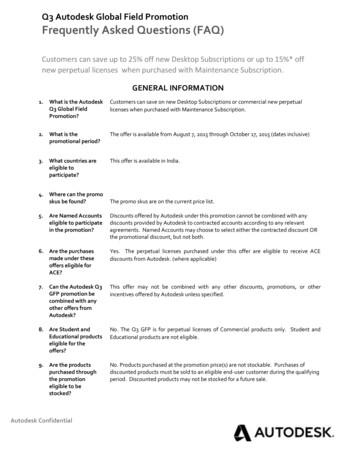
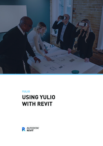
BD21-1L Autodesk Revit Building Family Editor: From The Beginning01. INTRODUCTIONA. Open Family template: File New Family Generic Model.rfaB. The Revit Family Editor User InterfaceC. Things we do Repeatedly during this Lab1. Family Typesa. Click Family Types button on Design BarThis is where we gain access to the parameters of each family. It is also where wecreate formulas for parameters and define types for a family.2. Element Propertiesa. Pick a Reference Plane Right Click Choose Properties orb. Click Properties button on options barWe can pick the options bar button next to the type selector or Right Click and choosethe Properties option.Lab Intro2
BD21-1L Autodesk Revit Building Family Editor: From The Beginning3. Apply Labelsa. Copy Reference Plane (Left/Right) to the left 3’-0”b. Add dimension between themc. Press ESC twice Pick dimension Click “None” next Label on options barThe parameters we can apply to dimensions are called Labels. These are accessedfrom the Options Bar or Right Click Edit Label, after picking a dimension.d. Cancel everything4. Link Parameters between Host and Nested componentsa. File Load From Library Load Familyb. Browse to Imperial Library Casework Domestic Kitchenc. Choose: Base Cabinet-2 Bin.rfa place it randomlyd. Press ESC twice Pick cabinet Right Click Choose Propertiese. Click Edit/New Notice the parameters and the little gray button on the farright.Parameters in nested families need to be linked to parameters in the host family. This isaccomplished by clicking a small subtle gray button in the Type Properties form of anested family.A parameter that is linked will display “ ” in the button and those that are not, won’t.5. File Close Don’t Save 02. GENERAL ADVICEA. Use snaps and snap overridesB. Make sure you select the object as a reference that you intendedLab Intro3
BD21-1L Autodesk Revit Building Family Editor: From The BeginningC. Use temporary hide/isolate to make sure only the objects you want to reference arevisibleD. Alter dimension style(s) so it/they work(s) better for laying out your family, removeextension line offset, decrease text size etc.E. Dimension only to reference planes, align/lock solids/voids to reference planesF. If you ignore #4, don’t do both “in the sketch” and “outside the sketch”G. Don't move the "origin", check the location of the origin by importing a dwg withlinework representing 0,0, and use “Origin to Origin” if you think you did. A littlebackground, if you move the reference planes defining the origin you will think theplacement origin is moved. In fact the reference planes don't really define the originanymore because Revit maintains the original origin is actual the internal 0,0 forplacement. This is a bug.H. Don't use "-" in parameter names because it turns into a minus if you use theparameter in a formulaI. Change the scale of the view to make it easier to constrain, select geometry.besure to test the family at various scales. Lineweights, graphic performance,particularly if nested annotation are included.J. Add additional types to the host in hosted families. This makes it faster to test fordifferent host thicknesses.K. Don't define materials in families, use sub-categories as much as possibleL. Don't include parameters in families that don't change geometry, instead put themin project templates and apply them to the categories they affect.M. Don't dimension objects inside a sketch and then constrain the object outside thesketch, either all in or out. The exception to this is the depth of an extrusion whichyou can constrain outside of a sketch because you can’t constrain it withdimensions elsewhere. It is safer to align/lock to reference planes.N. Angles and arcs are hardest to constrain. Save them for last and use Hide/Isolateto remove unnecessary objects from view so it is easier to ensure you constrain theright parts.O. Window and Door cuts per family cut planeP. Make a system type parameter into an instance parameter, select label in view,check instance parameter in option bar.Q. Shared families can only pass instance based parametersR. Voids don't allow visibility on/off or level of detailS. Mirror does not copy locks03. CREATE THE HOST FAMILY (SETTING THE STAGE)A. Use Door Family template1. FILE NEW FAMILY Door.rft2. FILE SAVE BROWSE to: MY DOCUMENTS Name: AU 2005 DoorLab Intro4
BD21-1L Autodesk Revit Building Family Editor: From The BeginningWhen you choose SAVE, Revit knows the file is a template and asks you for a newname. Revit will add the extension “RFA” automatically.3. Open View: Ref. Level Maximize view windowTIP! You know you can double click the blue bar? It’s a “Windows” thing 4. Change View Scale: 1” 1’-0”Increasing the scale will make the geometry larger and the relative size of dimensionssmaller, and easier to see everything.5. Delete the trim: Select the trim objects6. RIGHT CLICK Choose: DeleteWhy are we deleting these? Don’t need them it is a masonry door family!7. CLICK: Family Types (design bar)a. Remove parameter: Frame Project Ext. Trim Projection Exteriorb. Click: YESc. Repeat Remove Parameter: Frame Projection Int. Trim Projection Interiord. Repeat Remove Parameter: Frame Width Trim Width InteriorExercise 15
BD21-1L Autodesk Revit Building Family Editor: From The Beginninge. Click: OKB. Move the EQ dimension down below the wall to get it out of our wayC. Delete dimension in Exterior ElevationWe need to do the width a little differently to allow for a jamb and to calculate our roughopening. Leaving this here would generate an error later and be confusing.1. Open View: Elevations (Elevation 1): Exterior2. Pick Dimension with Label: Width Delete3. Close ViewD. Adding additional wall types to host wallThis will make testing/flexing our family easier, faster1. Create the additional wall typesa. Select the wall objectb. Click: Propertiesc. Click: Edit/Newd. Click: Duplicatee. Accept new wall name offered: Wall 2 Click: OKf. Click: Duplicate (yes, a second time)g. Accept new name offered: Wall 3 Click: OKExercise 16
BD21-1L Autodesk Revit Building Family Editor: From The BeginningE. Change the width for each wall typeBTW, We should still be viewing the type parameters for Wall 3, if not let’s get back onthe same “wall”.1. Click: Structure’s EDIT buttonYes it really is a button even though it is long and doesn’t really look like buttons you areused to looking at. A seasoned Revit user has gotten over this by now, but new usersare sometimes confused when you ask them to click the “edit button”.2. Change the thickness for type: Wall 3: 1’-6” WidthYes, you click inside the field just like Excel to edit the value. You can enter 0 18, 0-18,1-6, 1’-6”, 1’-6, 18” Revit assumes feet and wants a foot value, a space and an inchvalue when you don’t supply the ‘ mark or “ mark so no need to enter them if you don’twant to.3. Repeat for type: Wall 2: 1’-0” Width4. Repeat for type: Wall 1: 0’-6” Width (already set to this)F. Adjustable Door InsetWe need a Reference Plane so we can move the door assembly in or out within theopening.1. Change Wall Type: Type 32. Draw Reference Plane between the host wall’s exterior face and the referenceplane Center (Front/Back)3. Name Reference Plane: Door Inset IsReference: Weak Referencea. Select the Reference Plane, Right Click, choose PropertiesExercise 17
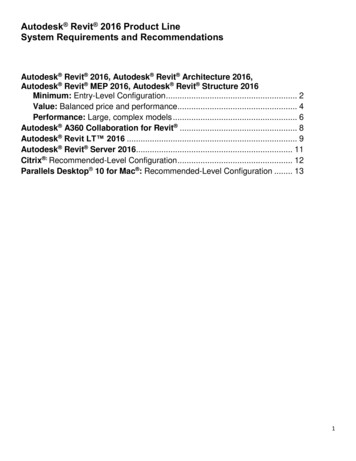
BD21-1L Autodesk Revit Building Family Editor: From The Beginning4. Add dimension between Reference Plane and Exterior Face of Wall5. Select Reference Plane Change Dimension value: 0’-2”6. Add Parameter to dimensiona. Select the dimension Click Label:None Choose Add parameter b. Assign the values to match this imageA reasonable argument could be made for this to be an instance parameter. For thesake of this lab we’ll just use Type.G. Wall Offset Alignment Feature1. Add Reference Planes on either side of the openinga. Position: 6” from the Right And Left Reference Planesb. Name: Wall Offset Right and Left accordinglyc. IsReference: Strong Reference2. Add dimension between each and Left and Right Reference planes3. Add Label for Reference Plane Wall Offset Lefta. Name: Wall Offset Left Group: Constraints4. Add Label for Reference Plane Wall Offset Righta. Name: Wall Offset Right Group: ConstraintsExercise 18
BD21-1L Autodesk Revit Building Family Editor: From The BeginningH. Rough Opening & Jamb Width1. Copy Reference Plane: Righta. To the left: 0’-2” Name: Jamb Right IsReference: Weak2. Copy Reference Plane: Lefta. To the right: 0’-2” Name: Jamb Left IsReference: Weak3. Add Dimension between each new reference plane and Reference Plane Rightand Left4. Add Label to each Dimensiona. Name: Jamb Width Group: Dimensions5. Add a formula to parameter Rough Widtha. Design Bar Family Typesb. Parameter: Rough Width Formula: Width (Jamb Width * 2)6. Increase the width of the openinga. Pick the dimension string between Reference Plane Right and LeftThe dimension string with the EQ toggle onExercise 19
BD21-1L Autodesk Revit Building Family Editor: From The Beginningb. Toggle the EQ offThis will let us adjust the opening without shifting the layout undesireably. If we didn’tdelete the width dimension earlier we would have seen unexpected behaviour whileadjusting the width.c. Pick Reference Plane: Right Change dimension value: 1’-8”d. Pick Reference Plane: Left Change dimension value: 1’-8”e. Press ESC twice Select the dimension string again Toggle EQ on7. Add dimension between Reference planes: Right & Lefta. Add Label to dimension string Select Rough Width from listThere is no need to apply the Width parameter since the combination of Jamb Width andRough Width are defining it for us. Besides the Width parameter drives the whole thing,since it is part of the formula we placed in Rough Width.I. Add Jamb Head Reference Plane to Elevation View1. Open View Elevations (Elevation 1): Exterior2. Copy Reference Plane: Top down 0’-4”3. Pick copy Right Click Properties Name: Head Bottom4. Add dimension between Reference Plane: Top & Head Bottom5. Add Label to dimensiona. Name: Head Width Group: Dimensions Type OK / OKJ. Add formula to parameter: Rough Height1. Click Family Types Click in Formula column next to Rough Height2. Type Formula: Height Head Width3. In View Elevations (Elevation 1): Exterior select dimension with Height label4. Switch labels from Height to Rough Height (choose from list)Exercise 110
BD21-1L Autodesk Revit Building Family Editor: From The BeginningK. Testing/Flexing/Save1. Experiment with parameter values2. Open View 3D Views: View 1a. View Orient Northwest Press F8 Click Save Icon3. File / Save or Click SAVE icon on ToolbarL. File Close04. CREATE THE SHARED PARAMETERA. File Shared Parameters1. Click: Create2. Name the file (put it in My Documents)3. Create the group4. Name: AU LabExercise 111
BD21-1L Autodesk Revit Building Family Editor: From The Beginning5. Create the shared parameter6. Name: Undercuta. Type: Length7. Click: OK OK05. APPLY THE SHARE PARAMETERA. Create a parameter using the shared parameter UndercutB. (Design Bar) Click: Family TypesC. In the Parameters Frame, click: AddD. Click Radio button for Shared Parameter, the Click Select ButtonBecause we just defined the shared parameter file we don’t need to browse to find it.Revit will remember the last shared parameter file we created until we point to another orit can’t find that last one.Exercise 212
BD21-1L Autodesk Revit Building Family Editor: From The BeginningE. Choose the Undercut parameter from the list, click OKF. Group: DimensionsYou could easily argue that this should be an instance parameter but for this exercise wewill let it be Type.G. Click OK06. BUILDING THE DOOR PANELA. Use Generic Model TemplateWhy? Starting out with this template means we can build it without a host object.1. New Family Generic Model.rft2. SaveAs AU 2005 Door Panel.rfa (My Documents)3. Maximize view: Ref. Level4. Change View Scale: 1-1/2” 1’-0”B. Convert to Door CategoryWhy? Now that we don’t have a host object, it allows us to use predefined subcategories for doors when we want to assign solids to a category.1. Settings Family Category and Parameters2. Check: Doors3. Check: Work Plane-Based4. Un-Check: Always VerticalWe need Work Plane-Based to permit us to later use the work plane of a reference lineto control the rotation of the panel in the host family.C. Layout Reference Planes in Plan ViewExercise 313
BD21-1L Autodesk Revit Building Family Editor: From The Beginning1. RIGHT - Copy Reference Plane: Center (Left/Right)a. To the right: 1’-6”b. Name: Right IsReference: Rightc. Origin: Yesd. Pin Reference Plane positionWhy? We need this panel to flex from one side, not center outward. If we don’t do this, itwill move around undesirably in the host family.2. LEFT - Mirror Reference Plane: Righta. Pick Reference Plane: Center (Left/Right) as axis of reflectionb. Name: Left IsReference: Left3. FRONT - Copy Reference Plane: Center (Front/Back)a. Up: 0-7/8”b. Name: Front IsReference: Frontc. Origin: Yesd. Pin Reference Plane Position4. BACK - Mirror Reference Plane Fronta. Pick Reference Plane: Center (Front/Back) as axis of reflectionb. Name: Back IsReference: Back5. MULLION FRONT - Copy Reference Plane: Center (Front/Back)a. Up 3/8”b. Name: Mullion Front IsReference: Not a Reference6. MULLION BACK - Mirror Reference Plane: Mullion Fronta. Pick Reference Plane Center (Front/Back) as axis of reflectionb. Name: Mullion Back IsReference: Not a Reference7. GLAZING FRONT - Copy Reference Plane: Center (Front/Back)Exercise 414
BD21-1L Autodesk Revit Building Family Editor: From The Beginninga. Up 3/16”b. Name: Glazing Front IsReference: Not a Reference8. GLAZING BACK – Mirror Reference Plane Glazing Fronta. Pick Reference Plane: Glazing Front as axis of reflectionb. Name: Glazing Back IsReference: Not a Reference9. STILE INSIDE RIGHT – Copy Reference Plane Righta. To the left, inside of Reference Plane Right: 0’-5”b. Name: Stile Inside Right IsReference: Not a Reference10. STILE INSIDE LEFT – Copy Reference Plane Lefta. To the right, inside of Reference Plane Left: 0’-5”b. Name: Stile Inside Left IsReference: Not a ReferenceD. Dimension the Reference PlanesRemember to toggle the “EQ” option on the dimensions as shown aboveE. Label the Dimensions1. Width (stock parameter)2. Thickness (stock parameter)3. Thickness Glazing Group: Other4. Thickness Mullion Group: Other5. Stile Right Group: Other6. Stile Left Group: OtherF. Add Control (Flip Arrow)Exercise 415
BD21-1L Autodesk Revit Building Family Editor: From The Beginning1. Choose Double Horizontal & Double Vertical2. Place as shown here3. Cancel command press ESC twice or click ModifyG. Layout Reference Planes in Elevation View1. Open View Elevation: Fronta. Set View Scale: 1” 1’-0”2. Sketch a horizontal reference plane 7’-0” above Ref. Levela. Name: Top IsReference: Top3. Pick the Reference Plane we just sketched Copy Down: 0’-5”a. Name: Top Rail Inside IsReference: Not a Reference4. Sketch a horizontal reference plane 0’-2” above Ref. LevelExercise 416
BD21-1L Autodesk Revit Building Family Editor: From The Beginninga. Name: Panel Undercut IsReference: Weak Reference5. Sketch a horizontal reference plane 0’-10” above Ref. Levela. Name: Bottom Rail Inside IsReference: Not a ReferenceH. Dimension the Reference PlanesI. Label the Dimensions1. Label Height (from stock list)2. Label (Add Parameter) Rail Top Type: Length Group: Other3. Label (Add Parameter) Rail Bottom Type: Length Group: OtherJ. Add Shared Parameter (Refer to Exercise 3)1. Pick dimension Label (Add Parameter) Shared Parameter Select Undercut (from earlier file) Group: OtherK. Add Parameters1. Click: Family Types Add parametera. Mullion Width Type: Length Group: Other Value: 0’-3/4”b. Lite Width Type: Length Group: Other (calculated value)c. Lite Height Type: Length Group: Other (calculated value)Exercise 417
BD21-1L Autodesk Revit Building Family Editor: From The Beginning2. Create Parameters to change the number of litesa. Lites Horizontal Type: Integer Group: Constraintsb. Lites Vertical Type: Integer Group: Constraintsc. Note to User Type: Text Group: ConstraintsUsing groups here to just segregate the parameters. Trying to make it a little easier todiscern things.3. Assign maximum number of lites and provide “note to user”L. Add Calculations to parametersRemember parameters in formulas are Case Sensitive!a. Enter Partial formula: ((Width - (Stile Right Stile Left)) - ((Lites Horizontal - 1)* Mullion Width))Adding the formula in two stages will prevent an error that I haven’t discovered thecause. Any ideas?b. Click Applyc. Add at end of formula: / Lites Horizontald. Click Apply2. Parameter Lite Heighta. ((Height - (Rail Top Rail Bottom)) - ((Lites Vertical - 1) * Mullion Width))This formula typically works when everything is entered at once but will repeat theprocess for consistency.b. Click Applyc. Add at end of formula: /Lites Verticald. Click ApplyThis is the closest thing we’ve got to LISP (“Lost in Silly Parenthesis”)M. Make a new Dimension StyleTo make it easier to do the next step, first a new arrowhead, then dimension style1. Menu: SettingsExercise 418
BD21-1L Autodesk Revit Building Family Editor: From The Beginninga. Duplicate existing Type: Diagonal 1/8” Name: Diagonal 1/32”b. Tick Size: 1/32” Click: OK2. Menu: Settings3. Duplicate Name: VoidN. Create Lites with Void1. Void Form Void Extrusion2. Sketch small rectangle off to the side of the panel reference planes3. Add dimensions to sketch (Type: Void)4. Add Labels to Dimensions (use list)a. Lite Widthb. Lite HeightExercise 419
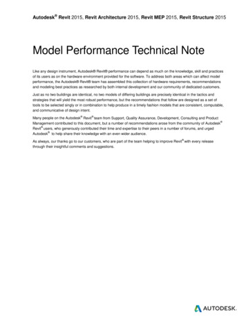
BD21-1L Autodesk Revit Building Family Editor: From The Beginning5. Copy the rectangle and dimensions To the Right, past the right side of theoriginal6. Add Dimension between the adjacent edges of the rectangles7. Add Label to Dimension Select Mullion Width from the list of choices8. Copy both rectangles To the right past the right side of the second rectangle9. Add Dimension Between the two inside rectangles adjacent edges (2x)10. Add label to Dimension Select Mullion Width from the list of choicesAt this stage we should see this what we see in this image11. Copy all four rectangles Up past the top of the existing rectangles12. Add Dimensions between each adjacent sketch line (4x)13. Add Label to Dimension Select Mullion Width from the list of choices (4x)14. Copy all eight rectangles Up past the top of the previous15. Add Dimensions between each adjacent sketch line (4x)16. Add Label to Dimension Select Mullion Width from the list of choices (4x)17. Copy all 16 rectangles Up past the previous18. Add Dimensions between each adjacent sketch line (4x)19. Add Label to Dimension Select Mullion Width from the list of choices (4x)Exercise 420
BD21-1L Autodesk Revit Building Family Editor: From The BeginningAfter this series we should see the following20. Align the bottom row with Reference Plane: Bottom Rail Insidea. Align Check: Multipleb. Pick Reference Plane: Bottom Rail Insidec. Pick bottom sketch line of each rectangled. Click Padlock as each appears (4x)21. Align left side of Rectangle cluster to Reference Plane: Stile Inside Lefta. Align (Multiple still checked)b. Pick Reference Plane: Stile Inside Leftc. Pick each outside sketch line from the left column of rectanglesd. Click the padlock as each appears (8x)22. Adjust the dimensions that stay behinda. Select the dimensions Nudge them into positionExercise 421
BD21-1L Autodesk Revit Building Family Editor: From The Beginningb. Finish Sketch of Void (should look like this)The void isn’t cutting anything yet so it is easy to see Align/Lock the depth of the void23. Open View: Floor Plans: Ref. Level24. Select Void Drag upper edge beyond Reference Planes25. Align (uncheck Multiple) Pick Reference Plane: Front Pick front of void Click Padlock26. Align Pick Reference Plane: Back Pick back of void Click PadlockO. Add a Solid Mullion (Sketching loosely, Align/Lock)1. Open View Elevations: Front2. Sketch the solida. Solid Form Solid Extrusion Sketch Lines RectangleSketch the rectangle larger than the panel reference planes taking care not to drawdirectly on top of any reference planes.b. Align/Lock sketch lines to Reference Planes: Top Rail Inside, Bottom RailInside, Stile Inside Right and Stile Inside Left (per following image)Exercise 422
BD21-1L Autodesk Revit Building Family Editor: From The BeginningBeware where you pick to choose the reference planes for alignment. If the object youwant doesn’t highlight check the status bar (and/or tool tip) to see what Revit is offeringfor selection. As a rule try to pick somewhere that isn’t covered by other geometry. Tabif necessary to pick the correct object. Don’t forget Temporary Hide/Isolate will help too!3. Assign sub-categorya. Menu: Settings Object Styles Click New Name: Mullion OKb. Click Extrusion Properties Choose Subcategory Mullionc. Finish Sketch4. Set depth of Solid Mulliona. Open View Floor plans: Ref. Levelb. Select solid drag upper grip past reference planesc. Align/Lock Mullion Front to Reference Plane: Mullion Frontd. Align/Lock Mullion Back to Reference Plane: Mullion Back5. Cut Geometrya. Open View: 3D Views: [3D]b. Click Cut Geometry Pick Void Pick SolidExercise 423
BD21-1L Autodesk Revit Building Family Editor: From The BeginningP. Add Solid Glazing (Sketch Loosely, Drag/Lock)1. Open View Elevations: Front2. Solid Form Solid Extrusion Sketch Lines RectangleSketch the rectangle larger than the panel reference planes taking care not to drawdirectly on top of any reference planes.a. Pick/Drag/Lock sketch lines over Reference Planes: (4x) Top Rail Inside,Bottom Rail Inside, Stile Inside Right and Stile Inside LeftPay close attention to the status bar to confirm that Revit finds the reference planes andlocking will relate to the correct element.b. Assign Subcategory Click Extrusion Properties Subcategory: GlassIf we look at the door in a 3D view we won’t see materials set because the Object Stylefor glass doesn’t have a material assigned.c. Finish Sketchd. Menu: Settings Objects Styles Glass Assign Material: GlassAs long as objects in the family are not assigned a specific material, just By Category,the Subcategory value will take precedence and the project material assignments willgovern when it is loaded into a project.3. Set Depth of Solid Glazinga. Open View Floor Plans: Ref. Levelb. Pick Solid Glazing Drag upper grip above reference planesc. Align/Lock Front of Solid to reference plane: Glazing Frontd. Align/Lock Back of Solid to reference plane: Glazing BackQ. Add Solid Frame (Pick/Lock)a. Open View Elevations: Frontb. Solid Form Solid Extrusion Lines Pick Tool (Check Lock Option)Exercise 424
BD21-1L Autodesk Revit Building Family Editor: From The Beginningc. Pick Reference Planes: Top, Right, Left and Undercutd. Trim corners of sketch Trim/Extend to Corner optione. Sketch Lines Pick Tool (Check Lock Option)f. Pick Reference Planes: Top Rail Inside, Bottom Rail Inside, Stile Right Inside &Stile Left Insideg. Trim corners of sketch Trim/Extend to Corner optionPick on a part of the reference plane that isn’t covered by or covering anything else, tomake it easier.h. Assign Subcategory Extrusion Properties Subcategory: Paneli. Finish Sketch2. Set depth of Solid Framea. Open View Floor Plans: Ref. Levelb. Pick solid Drag upper grip past reference planesc. Align/Lock Panel Front to Reference Plane: Frontd. Align/Lock panel back to Reference Plane: BackR. FLEX / SAVE1. Open View Default 3D View (Click the “3D House” toolbar button)2. Change parameters3. Open View 3D Views: View 1 Press F84. Expand Dynamic Modify View dialog to see orientation optionsa. Click Save icon to save view configurationS. Change Object Style settings for the family (optional)1. Settings Object Styles Change objects assigned to colors to use blackT. File SaveU. File Close07. BUILDING THE 2D DOOR SWING DETAILA. Justification1. Doing so reduces the effort of reproducing this graphic representation in othersimilar families. We just have to load the family, position it and assign a fewparameters to govern how it displays.Exercise 425
BD21-1L Autodesk Revit Building Family Editor: From The BeginningB. Setup1. File New Family Generic Model.rft2. File SaveAs AU 2005 Door Swing.rfa (My Documents)3. Menu: Settings Family Category and Parametersa. Check: Doorsb. Uncheck: Always VerticalOr should we? Hey Autodesk Guys, whadya think? Can you explain this feature?4. Maximize View5. Increase the Scale of the viewa. 1" 1'-0"C. Add Object Style1. Menu: Settings Object Styles New Name: Plan SwingThis is to match up with the object style found in stock Revit door families.2. Lineweight: Projection 1 Cut 1D. Reference Planes1. Reduce the extents so that the drawing area is smaller and closer to the size ofthe symbology we are creating2. Copy Right 3'-0" to the left, Name: Left IsReference: Left3. Rename Center (Left/Right) Name: Right IsReference: Right Check: OriginEntering values in the IsReference you can just click in the field and enter the first letterof the name you want. You can also copy/paste the text into the Name field4. Rename Center (Front/Back) Name: Front IsReference: Front Check: Origin5. Adjust the ref planes so they look like thisExercise 526
BD21-1L Autodesk Revit Building Family Editor: From The BeginningE. Sketching1. Sketch 1st line of panela. Symbolic Line Type: Panel (Cut)b. From intersection of Ref Planes Right and Front at 45 degrees and 3 feet long2. Sketch 2nd linea. Symbolic Line Type: Panel (Cut)b. From second point of first line perpendicular to the line toward the left and 2"long3. Sketch 3rd Linea. Symbolic Line Type: Panel (Cut)b. From end of second line parallel to first line till the second end of the line isparallel to the first point of the first lineSketch 4th Line4. Sketch 4th linea. Symbolic Line Type: Panel (Cut)b. Close the rectangle of the panelExercise 527
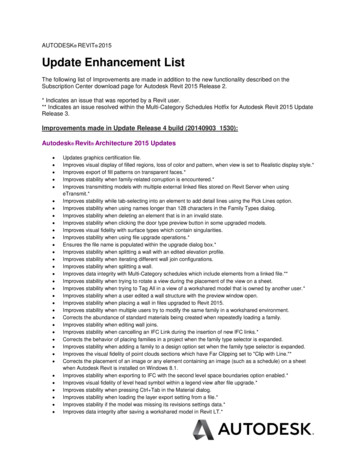
BD21-1L Autodesk Revit Building Family Editor: From The Beginning5. Sketch 5th Linea. Model Line Type: Invisibleb. From the intersection of Ref plane Right and Front (make sure it is theintersection of them)c. Sketch away from start point, left and below Reference Plane: Front, a coupledegrees below6. Sketch 6th Linea. Pick invisible line and four (4) panel sketch lines Temporary Hide/Isolate Hide Objectb. Symbolic Line Type: Plan Swing (projection) Option: Arc From Center EndPointsc. Place center for Arc at intersection of ref planes Right and Front. First endpointof arc from intersection of ref planes Left and Front. Sketch last point up andtoward the panel sketch lines that are hidden, pick a point nearby.d. Reset Temporary Hide/Isolatee. Pick the Arc segment Drag bottom grip to the invisible line Drag upper gripto outside upper corner of panel sketchExercise 528
BD21-1L Autodesk Revit Building Family Editor: From The BeginningF. Dimensioning1. Add Angular Dimension: Swing Anglea. Between outer edge of panel and Reference Plane: Front2. Add Linear Dimension: Thicknessa. Between long sides of panel3. Add Linear Dimension: Width (for system parameter)a. Add width dimension between short sides of rectangle panel4. Add Angular Dimensiona. Between invisible line and outside edge of panel. Adju
INTRODUCTION A. Open Family template: File New Family Generic Model.rfa B. The Revit Family Editor User Interface , C. Things we do Repeatedly during this Lab 1. Family Types a. Click Family Types button on Design Bar This is where we gain access to the parameters of each family.