Transcription
INSTALLATIONGUIDETHERMOSTATIC SHOWER MIXER3 Outlets
Thermostatic Shower MixerIMPORTANT - PLEASE READPlease read these instructions carefully before starting installation andkeep for future reference.Check the product for missing parts or damage before startinginstallation.Any alterations made to this product and fittings may infringe waterregulations and will invalidate the guarantee.The installation must comply with all Local/National Water SupplyAuthority Regulations/Byelaws and Building and Plumbing (UK:BS6700)Regulations.This product should only be fitted by a qualified plumber, it mayinvalidate the guarantee if fitted by a non-qualified person.Specification2Minimum Pressure0.5 barMaximum Pressure5.0 barRecommended pressure1.0-3.0 bar balancedInletsG3/4” Hot and ColdOutlets2x G3/4” Mixed and 1x G1/2” MixedHot Supply Temperature55-65 ⁰ CCold Supply Temperature4-20 ⁰ C
Installation InstructionsGENERAL INSTALLATIONThis shower valve is a mixing device so the inlet pressures must bereasonably balanced.For ease of maintenance it is recommended that isolation valves arefitted to the inlet feeds.All supply pipes MUST be thoroughly flushed to remove any debris priorto making any connection to the valve. Failure to do so could result indamage or low flow from the mixer unit.The valve is supplied with a cover plate as protection during fitting, thisshould remain in place until second fixing.Note: When pressure is higher than 5 bar a pressure reducer is required tobe fitted before the valve.3
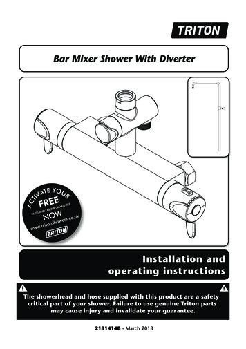
Thermostatic Shower MixerTypical installation showing depth of the valve from finished wall surface72 mm MIN91mm MAXFinshed wall surfaceTiled or panelled face.Wall boardingTypical installation showing depth of valve from finished wall surface4
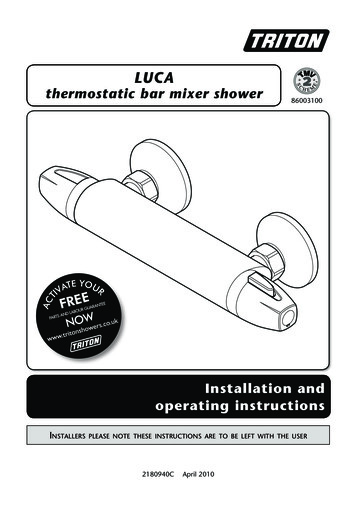
Installation InstructionsDimensions 1st fix partDimensions1stfirstfix partDimensionsfix - valve 35828272 min.8282Dimensions as FittedDimensions as Fitted91 asFitted72 min.72 min.min.91 73max.91 max.91 max.73 min.91 max.91 max.72 min.91 max.91 max.72 min.72 min.G3/4" HotInletG3/4" HotInletG3/4" HotG3/4" HotInletInletG3/4" ColdInlet139G3/4" ColdInlet139139139G3/4" ColdInletG3/4" ColdInlet5
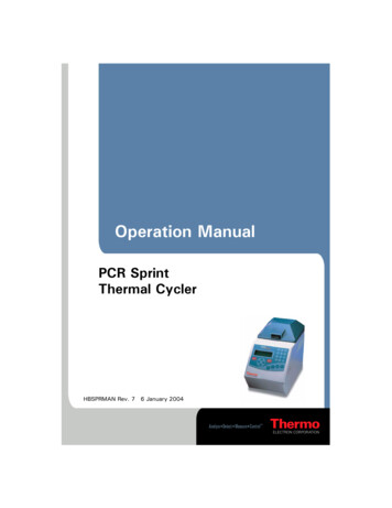
Thermostatic Shower Mixer2 Way Outlets1 Way Outlet3 WayOutletG3/4" MixedOutletG3/4"MixedOutletG1/2" MixedOutlet280Fascia PlateHandle Pack1302 Way OutletsG3/4" Handle Pack - according to choice2806
Installation InstructionsINSTALLATION STEPS1Select the position for the showervalve and offer the shower valve to thewall.Make sure the valve is set back tothe appropriate depth from the finished wallsurface,allowingDETAILE for boarding and tiling. ForstudwallsabattenSCALE 1 : 2 or suitable fixing plate canbe used.Ensure the valve is vertical with a level andmark the 4 fixings. Prepare the supply andoutlet pipes as required.DETAIL EFixthe valveSCALE1 :in2place and connect the pipework.Note: It is recommended that isolation valvesare fitted to the inlet feeds.2Board the wall, we recommend asuitable waterproof board is used andseal the edges of the Easi-Box.7
Thermostatic Shower Mixer3Finish the wall by tiling or panelingup to the Easi-Box, keep the finalfinished wall surface between themin and max guides marked on theEasi-Box.DETAIL FSCALE 1 : 24Remove the protective cover.DETAIL FSCALE 1 : 28
AIL IInstallation Instructions5Trim away any excess from the lip of theEasi-Box using a sharp blade, ensuringthat none of the lip protrudes beyond thefinished wall surface.Ensure the stop ring on the thermostatic valve isorientated as indicated in the diagram.DETAIL HSCALE 1 : 2DETAIL HSCALE 1 : 26Attach the escutcheon pieces byscrewing onto the threads on thevalve body.9
Thermostatic Shower Mixer7Apply a little silicone grease to theO rings of the fascia plate and anarrow bead of silicone sealant tothe back and slide into place .8Fit the control knobs ensuring thestop pin of the temperature handleis located against the top of thestop ring.10
Installation Instructions9RRe-calibrationTpApaThe valve is factory set under balancedpressure with specific inlet temperatures.As site conditions may differ, thetemperature may require re-setting according to siteconditions.RttRemove the temperature handle and turn on thevalve and allow the output temperature to stabilise.TtTurn the spindle until a constant temperature of38⁰C is achieved.RaEnsure the stop ring is fitted correctly as indicated.Replace the handle so the stop pin sits against theIL N stop ring.1:2M10MaintenanceOcOver a period of time limescaleand debris can affect theperformance of the valve.IcIt is recommended that regular cleaning iscarried out to maintain performance.FTRRfRrAFilter CleaningTurn off the water supply. Remove the handlesand face plate. Remove the filter covers (A) andremove the filters and non-return valves thenvisible.TTRRRwARun these under hot water and wipe to removeany build of debris.LL1 : 2 Thermostat CleaningTurn off the water supply. Remove the handlesand face plate. Remove the thermostatic valve.Run the thermostatic valve under hot water andwipe to remove any build of debris.11Ma
Thermostatic Shower Mixer12
seal the edges of the Easi-Box. E 1 DETAIL E SCALE 1 : 2 E DETAIL E SCALE 1 : 2 1. Select the position for the shower valve and offer the shower valve to the wall. Make sure the valve is set back to the appropriate depth from the finished wall surface, allowing for boarding and tiling. For stud walls a batten or suitable fixing plate can be used.