Transcription
MarkimicrowaveMixer Basics PrimerA Tutorial for RF & Microwave Mixersby: Ferenc Marki & Christopher Marki, Ph.D. 2010 Marki Microwave, Inc. 215 Vineyard Court Morgan Hill, CA 95037P 408.778.4200 F 408.778.4300 info@markimicrowave.com
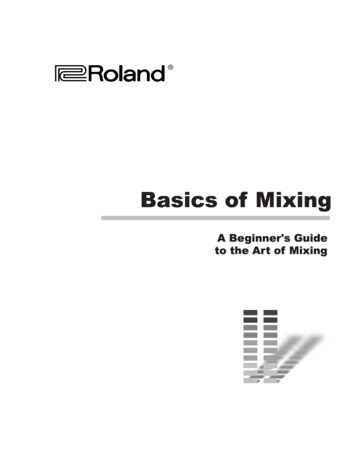
MSection 1DOWNCONVERSIONUPCONVERSIONfIF fLO - fRF fRF1 fLO - fIFfRF2 fLO fIFLOLOIFRFRF1IFDCRadio Frequency(fRF)RF2PowerPowericrowave mixers translate the frequency ofelectromagnetic signals. This functionality is vital for anenormous number of applications ranging from militaryradar and surveillance to radio astronomy to biologicalsensing. Despite their ubiquity, however, microwavefrequency mixers remain one of the most misunderstoodcomponents available in the RF/microwave engineer’stoolbox. This Mixer Basics Primer intends to shed lighton the “dark art” of microwave mixers to help ourcustomers better understand, select, and ultimately useMarki Microwave mixers.FrequencyRLIIntermediate Frequency(fIF)DCRadio Frequency(fRF)Local Oscillator(fLO)FrequencyRLIIntermediate Frequency(fIF)Local Oscillator(fLO)Figure 1: Definitions of downconversion and upconversion.What is a mixer?A frequency mixer is a 3-port electronic circuit. Twoof the ports are “input” ports and the other port is an“output” port1. The ideal mixer “mixes” the two inputsignals such that the output signal frequency is eitherthe sum (or difference) frequency of the inputs as shownin Fig. 1. In other words:fout fin1 ! fin2(1)The nomenclature for the 3 mixer ports are the LocalOscillator (LO) port, the Radio Frequency (RF) port, andthe Intermediate Frequency (IF) port. The LO port istypically driven with either a sinusoidal continuous wave(CW) signal or a square wave signal. The choice to applya CW or square wave signal depends on the applicationand the mixer. Conceptually, the LO signal acts as the“gate” of the mixer in the sense that the mixer can beconsidered “ON” when the LO is a large voltage and“OFF” when the LO is a small voltage. The LO port isusually used as an input port.The other 2 ports of the mixer, the RF and IF, can beinterchanged as either the second input or the output—the actual configuration depends on the application.When the desired output frequency is lower than thesecond input frequency, then the process is calleddownconversion and the RF is the input and the IF isthe output. The relationship between input and outputfrequencies is given by:fIF fLO - fRF (2)On the other hand, when the desired output frequencyis higher than the second input frequency, then theprocess is called upconversion and the IF is the input andthe RF is output. A frequency domain representation ofdownconversion and upconversion is illustrated in Fig.1. Take careful note of the upconversion case—the closeproximity of the sum and difference frequencies (fRF1and fRF2) in the frequency domain implies that both areavailable at the RF output port. This type of upconversionis known as double sideband upconversion. Singlesideband upconversion is also possible, in which caseeither the sum or the difference frequency is intentionallycanceled inside the mixer. Mixers that perform this moresophisticated functionality are called single sideband(SSB) upconverters (or single sideband modulators) andwill be addressed in a future article.As Fig. 1 depicts, IF/RF signals tend to be informationbearing signals (as denoted by the broadened spectrasurrounding the RF and IF center frequencies). Duringfrequency conversion, the information carried by theRF (IF) signal is frequency translated to the IF (RF)output. Therefore, mixers perform the critical functionof translating in the frequency domain.In principle, any nonlinear device can be used to makea mixer circuit. As it happens, only a few nonlineardevices make “good” mixers. The devices of choicefor modern mixer designers are Schottky diodes, GaAsFETs and CMOS transistors. The choice depends on theapplication. FET and CMOS mixers are typically usedin higher volume applications where cost is the maindriver and performance is less important. For the morechallenging, high performance applications, Schottkydiode mixers are used almost exclusively. All MarkiMicrowave mixers are designed using Schottky diodetechnology. For this reason, this Tutorial will focus on1Actually, all three ports of a mixer behave as both a load and a source. We will ignore this fact for the moment and save it for a later discussion. An excellent resource on this topiccan be found in [1]. 2010 Marki Microwave, Inc. 215 Vineyard Court Morgan Hill, CA 95037P 408.778.4200 F 408.778.4300 info@markimicrowave.comMarkimicrowave
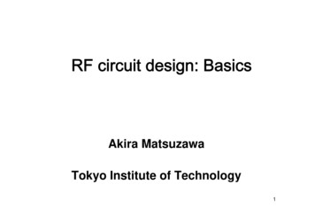
diode mixers with only tacit reference to transistor-typemixers.(a)0.25VRFVLO -10-20-30-40-50-60-70-700Section 20.610-60Figure 2: (a) Simple single ended mixer. I-V characteristics for (b)the ideal commutator and (c) a realistic Schottky diode.0.4Realistic DiodeFrequency Domain0(c)0.2(d)Ideal CommutatorFrequency Domain10TransitionRegionVoltage0.2(c)Relative Amplitude (dB)Current(b)0.20.150.0Actual Schottky DiodeCurrentIdeal CommutatorRealistic DiodeTime Domain0.25Relative Amplitude (dB)(a)Voltage(b)Ideal CommutatorTime Domain5101520253035400510152025303540Figure 3: Time and frequency domain comparing the output ofthe single ended mixer in Figure 2 with ideal and relatistic diodeswitching characteristics.Single Diode Mixer: Ideal Commutator vs.Realistic Diodecommutator, only odd harmonics of the LO are allowedto mix with the fundamental RF tone.There are many ways to build a mixer. The simplest mixerconsists of a single diode as shown in Fig. 2a. A largesignal LO and a small signal RF combine at the anode ofthe diode. For an “ideal” single diode mixer, it is assumedthat the LO is significantly stronger than the RF such thatonly the LO has the ability to affect the transconductanceof the diode. We also assume that the diode switchesinstantaneously as shown in Fig. 2b. Devices thatpossess such instantaneous transconductance switchingare called ideal commutators and yield the theoreticallyoptimal diode mixer performance.Unfortunately, the transfer function of the idealcommutator can never be achieved in the real world.Actual Schottky diodes necessarily possess some amountof “turn-on” transition as shown in Fig. 2c. Moreover, theRF will modulate the diode transconductance to someextent—even if the RF is very small. The combination ofrealistic diode I-V characteristics and transconductancemodulation by the RF signal causes additional mixingproducts (often referred to as “spurs”). Thus real diodesproduce all possible harmonic mixing components! Thetime domain signal and associated frequency spectrumgenerated by a realistic Schottky diode are depictedin Fig. 3b and Fig. 3d. Mathematically, the frequencycomponents generated by a single diode are given by:The “mixing” process takes place due to the switchingresponse of the diode I-V curve to the strong LO signal.As the diode is forced open and closed by the LO,the small signal RF is “chopped”. When we analyzethe Fourier components of the output signal from acommutating (or switching) mixer diode (Fig. 3a andFig. 3c), we find that the possible output products followthe relation:fIF nfLO mfRF m and n are ALL integersh(4)(3)Because we only want one desired output frequency(when n 1 and m 1), the existence of all other harmonicterms creates significant problems. Elimination of thesedistortion products is a key goal in mixer design.Thus, in the ideal case of a perfectly switchingThis simplified analysis illustrates several importantfIF nfLO ! fRF (n is ODD only) 2010 Marki Microwave, Inc. 215 Vineyard Court Morgan Hill, CA 95037P 408.778.4200 F 408.778.4300 info@markimicrowave.comMarkimicrowave
attributes of frequency mixers:1. “Mixing” is caused by the switching behavior of thediode.2. The majority of unwanted harmonics are causedby the nonlinear intermodulation of the RF and LOsignals in the transition region of the diode.3. The best mixers use diodes that closely approximatethe ideal commutator.4. The lower the RF power, the better the spuriousperformance (since the LO will control the diodetransconductance more effectively).Section 3Mixer BalanceHigh performance mixers are designed using four oreight diodes. The evolution of the mixer circuit fromthe single diode unbalanced type to the multi-diodebalanced type is described in this Section. Much of thisinformation is a summary of [2].Sophisticated mixer designs make use of circuit symmetryto create “balance”. In fact, virtually all commericallyavailable mixers make use of some kind of mixerbalancing. Mixer balancing offers several advantages:inherent isolation among all mixer ports (and henceband flexibility), cancellation of most intermodulation124-PortHybrid Junction34Port 1Port 2Port 3Port nput/2Figure 4: Schematic and I/O table for a 4-port hybrid junction.LORF4-PortHybrid JunctionIFFigure 5: Single balanced mixer with 4-port hybrid junction.products, common mode signal rejection, and improvedconversion efficiency.In mixers, extra circuitry is needed to route and separate(i.e multiplex) input and output signals from the diodes—such is the cost for using a two terminal device toperform a three-port functionality. In single diode mixersthis extra circuitry consists of a combination of passivecoupling, power division, and filtering. It is difficult tocreate wideband single diode mixers with independentRF, LO, and IF bands since the multiplexing circuitry isfrequency specific. Moreover, such circuitry causes extralosses that reduce mixer efficiency.To solve this problem, clever engineers realized thatwideband single-balanced mixers with low loss andindependent input and output frequency bands couldbe created using the classic four port hybrid junction.The hybrid junction (aka the “magic tee” or the 180ohybrid), depicted in Fig. 4, is a two input, two output,four port circuit that provides mutual isolation betweeninput ports and equal power division at the output ports.One immediately sees the applicability of the hybridjunction for mixers: the input LO and RF sources willbe isolated from one another, thus providing frequencyband independence and equal power division to theload. The input/output transfer characteristics are listedin Fig. 4. Notice that the output signals are differentiallyphased (i.e. 180o phase shifted) when a signal is input toport 2. Output signals are in phase for inputs into port 1.The hybrid junction provides a natural method by whichto create the single balanced mixer as shown in Fig. 5.Additionally, two diodes are used instead of one. Keyfeatures of the single balanced mixer include:1. Isolation (and hence frequency independence)between RF and LO ports.2. 50% reduction in the total number of intermodulationproducts.3. Common mode noise cancellation (good for noisyLO).4. Higher conversion efficiency than the single diodemixer.Further, two single balanced mixers can combine toform the double balanced mixer as shown in Fig. 6. Inthis case, hybrid junctions are placed on both the RFand LO differential ports and the IF is obtained at the 2010 Marki Microwave, Inc. 215 Vineyard Court Morgan Hill, CA 95037P 408.778.4200 F 408.778.4300 info@markimicrowave.comMarkimicrowave
in phase port of the hybrid junction—The reciprocity ofthe hybrid junction allows this type of interconnection.Detailed analysis reveals that for the double balancedmixer, only ODD n and ODD m harmonic spurs cansurvive at the IF port [1]. Therefore, mixer doublebalancing has the benefit of reducing nearly 75% of thespurious interferers possible at the IF port. Owing toconservation of energy, double balanced mixers tend tohave better conversion efficiency than single ended orsingle balanced mixers, since energy cannot spread intothe EVEN order harmonics.A more complex mixer circuit is created using two doublebalanced mixers driven in a push-pull configuration (Fig.7). This “doubly double balanced” mixer has receivedthe ill-conceived title of the “triple balanced” mixer.Some of the key features of the triple balanced mixer areoverlapping RF, LO and IF bands and higher spurioussuppression. Marki Microwave T3 mixers are a specialsubset of triple balanced mixers and provide the highestspurious suppression possible by closely emulating theideal commutator switching behavior. The details andanalysis of the T3 mixer are available in [3].LOIF4-PortHybrid Junction4-PortHybrid JunctionRFSection 4Mixer Performance MetricsWhat makes a “good” mixer? Well—lots of things. Wewill now address some of the criteria by which to judge,and ultimately choose, a mixer.A. Conversion LossThe most important mixer metric is conversion loss.Conversion loss is defined as the difference in powerbetween the input RF power level and the desiredoutput IF frequency power level. In other words:CL PRF - PIF(5)where PRF and PIF are in dBm and CL is in dB. For example,if the input RF is -10 dBm and the downconverted IFoutput signal -17 dBm, then the conversion loss is 7 dB.The theoretically optimum conversion loss for a passivediode mixer is 3.9 dB and can be calculated using equations derived by Henderson [4]. Typical values of conversion loss range between about 4.5 to 9 dB, dependingon the mixer—the additional losses are caused by factors such as transmission line losses, balun mismatch, diode series resistance and mixer (im)balance. In generaldouble balanced mixers have less conversion loss thantriple balanced mixers because of circuit losses. Anotherimportant trend is that wider bandwidth mixers tend tohave higher conversion loss in part due to the difficultyin maintaining circuit balance over the entire bandwidth.Figure 6: Double balanced mixer.LO idJunction RF 4-PortHybridJunction 4-PortHybridJunction Conversion loss is the benchmark mixer metric becauseit correlates closely with other metrics like isolation and1 dB compression. Experience shows that for a maturemixer design such as the Marki Microwave M1-0220, asingle conversion loss measurement will indicate thequality of the unit. If the conversion loss of a unit is withina narrow specification, all other performance metrics willalso meet specifications. The converse is not necessarilytrue however; it is possible to have good isolation andpoor conversion loss, for example. Because conversionloss is the benchmark measurement for all mixers,Marki Microwave tests the conversion loss of all mixersproduced in the facility.B. IsolationIFFigure 7: Doubly double balanced mixer (aka triple balancedmixer).Isolation is a measure of the amount of power thatleaks from one mixer port to another. As was described 2010 Marki Microwave, Inc. 215 Vineyard Court Morgan Hill, CA 95037P 408.778.4200 F 408.778.4300 info@markimicrowave.comMarkimicrowave
previously, port isolation is obtained through mixerbalance and the use of hybrid junctions. Unfortunately,there will always be some small amount of powerleakage between the RF, LO and IF ports. Isolation isthe difference in power between the input signal andthe leaked power to the other ports. In other words, ifwe place an input signal at the LO port and measure thepower available at the RF port at that LO frequency, theisolation in dB is given by:PISO (L - R) Pin(@LO) - Pout(@RF)LO frequency is very close to the RF output frequency(when the IF frequency is at or near DC). In this case, noamount of filtering can separate the arbitrarily close RFsignal and LO leakage. This can result in interferencebetween the RF and LO and a degradation in the RFoutput circuitry.L-I isolation is the leakage of the LO into the IF port.L-I isolation tends to be the worst of the three types ofmixer isolation with typical values ranging from 20-30dB. When there is poor L-I isolation, the biggest issueoccurs when the LO and IF frequencies are close suchthat the LO contaminates the IF circuitry, as when theLO leakage is strong enough to saturate the IF amplifier.Beyond this, poor L-I isolation can cause conversion lossflatness problems.(6)Note that isolation is approximately reciprocal: the port1 to port 2 isolation will track closely with the port 2 toport 1 isolation. Hence, a single measurement can beperformed to determine the isolation in both directions.Three types of isolation are commonly quoted inmicrowave mixers: L-R isolation, L-I isolation and R-Iisolation. The definitions of each type of isolation areillustrated in Fig. 8.The final mixer isolation metric is R-I isolation. Valuesof R-I isolation typically range between 25-35 dB. Mostsystems designers will not find R-I isolation to be a majorissue since the RF and IF powers tend to be orders ofmagnitude smaller than the LO power. Therefore, LOisolation problems are the primary concern of systemsengineers. R-I isolation, instead, is a major concern formixer designers because it serves as a diagnostic metricfor the overall conversion efficiency of the mixer circuit.When the R-I isolation is high, the mixer circuit is wellbalanced and thus the conversion loss tends to be low.In mixers with bad R-I isolation ( 20 dB), the conversionloss is higher and the conversion loss flatness ispoor.L-R isolation is the leakage of the LO into the RF port.Typical L-R isolation values range between about 25-35dB. L-R isolation is critical in frequency downconversionsbecause LO power can leak into the RF circuitry. If thereis poor L-R isolation, LO power can contaminate theRF line by either interfering with the RF amplifier orby leaking to other parallel mixing channels causingcross-channel interference. Poor L-R isolation can alsocause problems in frequency upconversions when theRLIRPIN @ LOPOUT @ IN @ LOISOL-IPOUT @ IFFrequencyPowerPOUTPIN @ RFISOR-IPOUT @ IFFrequencyFigure 8: Definitions of mixer isolation for L-R, L-I and R-I isolation. 2010 Marki Microwave, Inc. 215 Vineyard Court Morgan Hill, CA 95037P 408.778.4200 F 408.778.4300 info@markimicrowave.comMarkimicrowave
C. 1 dB CompressionUnder normal (linear) operation, the conversion lossof the mixer will be constant, regardless of input RFpower. If the input RF power increases by 1 dB, then theoutput IF power will also increase by 1 dB (the powerdifference is the conversion loss). However, as the RFpower becomes too large, this dB for dB relationshipwill not hold. The 1 dB compression point is a measureof the linearity of the mixer and is defined as the inputRF power required to increase the conversion loss by 1dB from ideal.Mixer compression is most easily represented graphicallyas shown in Fig. 9. For low input RF power, the slopeof the line is 1:1 as described above. However, as theRF power increases, the mixer deviates from this linearbehavior and the conversion loss starts to increase.When the input/output curve “sags” by 1 dB (i.e theconversion loss increases by 1 dB), the input RF 1 dBcompression has been reached.Conceptually, the 1 dB compression point occurs whenthe RF signal can no longer be considered “small signal”.Under linear operation, the LO power is so much strongerthan the RF power that the diode switching action istotally dominated by the LO as described in Section 2.However, in compression, the RF power competes withthe LO power such that the diode switching action isIF OutputPower (dBm)compromised. When the RF power is within about 3 dBof 1 dB compression, the mixer behaves unpredictably.Among other effects, operating the mixer in compressioncauses increased levels of intermodulation distortionand higher conversion loss. This behavior is explainedby the fact that the compressed mixer spreads energyin the frequency domain because the diodes arebeing partially turned-on by the RF signal. Slight mixerimbalances are therefore exacerbated and the mixerconversion efficiency is degraded.Mixer compression can be improved by using higherturn-on diodes. In this way, a larger RF power can beapplied to the mixer without challenging the turn-onvoltage of the diode. The trade-off, of course, is that alarger LO drive must also be applied to switch the diodeON and OFF. As a rule of thumb, the 1 dB compressionpoint will be anywhere from 4-7 dB below the minimumrecommended LO drive level of the mixer. For lowbarrier “L” diodes, 1 dB compression occurs for inputRF powers 0 dBm. For super-high barrier “S” diodes, 1dB compression occurs for input RF power 12 dBm.State-of-the-art mixers such as the T3 series can be drivenwith any LO power 15 dBm and the corresponding 1dB compression point will be 3 to 4 dB below that drive.For example, a T3 driven with 18 dBm will compressaround 15 dBm. That same T3 driven with 25 dBm willcompress around 22 dBm. To our knowledge, no othermixer ever created offers the ability to linearly increasethe 1 dB compression point simply by increasing the LOdrive level.D. VSWR1 dBIdeal1:1 SlopeMeasuredCurveRF InputPower (dBm)ConversionLossInput 1 dBCompression PointFigure 9: Graphical representation of 1 dB compression point.Mixer VSWR is a contentious topic. It is our opinion thatVSWR is a meaningless metric for microwave mixersbecause it does not help to predict mixer performancenor does it guarantee proper operation when the mixeris integrated within the surrounding RF system. The cruxof the argument comes down to the fact that the mixercannot be modeled as a static load. In actuality, a mixeris both a load and a source. It can be easily shown that allthree mixer ports act as sources for the intermodulationdistortion intrinsic to the diodes [1]. Even if the VSWRof the mixer is perfect (i.e. no reflections of thefundamental), there will inevitably be harmonics comingout of the input ports.A classic mixer spur problem involves the 2*LO x 1*RF 2010 Marki Microwave, Inc. 215 Vineyard Court Morgan Hill, CA 95037P 408.778.4200 F 408.778.4300 info@markimicrowave.comMarkimicrowave
“image” spur. It can be shown that all EVEN LO x ODDRF spurs generated within the mixer are available atthe RF port [1]. A problem arises when the RF port isreactively terminated with, for example, a preselectionbandpass filter. Acting as a source, the mixer producesthe 2L x 1R image spur which exits the RF port andenters the RF filter. Most commonly, the 2L x 1R productwill lie outside the passband of the filter and will hencebe reflected back into the mixer as shown in Fig. 10.Upon re-entry into the mixer, the 2L x 1R image productwill mix with the LO and downconvert to the exact samefrequency as the desired difference frequency. In otherwords,OUTPUT SPECTRUMImage Spur2LO x 1RFLOBPFRLIOutputIFRadio Frequency(fRF)Local Oscillator(fLO)RFFilterBandwidthImageSpurFigure 10: Schematic diagram (left) showing backreflected 2LOx 1RF spur from reactive bandpass filter (BPF). Output spectrum(right) showing desired IF and downconverted image spur overlapping in frequency.fout fspur - fLOreceiver. Hence, when choosing mixers for low powerapplications, conversion loss should be as low aspossible.fout 2 fLO - fRF - fLOfout fLO - fRFfout fIF(7)The overlap of the downconverted image spur and thedesired IF creates substantial interference. The extentof the interference depends on the relative phasedifference between the two signals. If the RF frequency isswept, the relative phase will cycle from 0 to 2 π resultingin significant conversion loss ripple. A common concernis that conversion loss ripple is caused by poor mixerVSWR. However, as we have illustrated in this example,issues associated with the mixer acting as a source ofRF and LO products frequently lead to more seriousproblems if precautions are not taken.Always remember that all Marki Microwave mixer specifications are defined assuming wideband 50 Ω systems.In our experience, mixer VSWR is a minor concern compared to the myriad problems that arise when the mixerports are reactively terminated, such as in the aboveexample. To solve these problems we recommend increasing attenuation or using non-reflective terminations such as absorptive WavefadeTM low pass filters or50 Ω terminated diplexers.E. Noise FigureAs long as the quality of the diode is closely monitored,the noise figure of the mixer can be approximated bythe conversion loss. Generally, the cumulative noisefigure will limit the minimum detectable signal in theF. Single-tone Intermodulation DistortionMuch has already been said about the harmonic mixingproducts generated by the nonlinear mixing of theRF and LO signal in the transition region of the diodeI-V curve as given by (3) and illustrated in Fig. 3. Mostcommonly, the only desirable mixing term is given bym 1 and n 1 in (3) and all other unwanted harmonicterms are called single-tone IMD. A major goal in mixerdesign is to limit the strength of the single-tone IMDterms.The key features of single-tone IMD in double and triplebalanced mixers are:1. Only ODD n by m terms exist at the IF port in doubleand triple balanced mixers.2. Cancellation through mixer balance improvesEVEN by EVEN, EVEN by ODD and ODD by EVENharmonic levels by about 30 dB.3. The lower the RF input power, the better the singletone spurious performance.4. With the exception of the T3 mixer, increasingthe LO drive does not always improve spuriousperformance.Marki Microwave provides typical mixer spur tables forits double balanced, triple balanced and T3 mixer lines.For additional information on single-tone IMD in doublebalanced mixers, we recommend Bert Henderson’sanalysis on the prediction of mixer IMD [4]. 2010 Marki Microwave, Inc. 215 Vineyard Court Morgan Hill, CA 95037P 408.778.4200 F 408.778.4300 info@markimicrowave.comMarkimicrowave
G. Multi-tone Intermodulation DistortionMulti-tone IMD implies that multiple tones enter themixer through the same port and intermodulate in themixer diodes. Multi-tone IMD is a form of commonmode mixing in which two or more tones enter theRF port and nonlinearly mix with each other and theLO to create distortion as shown in Fig. 11. From theperspective of a system designer, multi-tone IMD is aserious problem because it can generate interferencetones that fall within the IF bandwidth of the receiver.Hence, multi-tone IMD places a theoretical upper limiton the dynamic range of the receiver.that the TOI is an extrapolated point because the mixerwould compress before the lines crossed. Nevertheless,the impact of the third-order interference products canbe debilitating in many systems at RF power well belowthe 1 dB compression point. The higher the TOI, thebetter the mixer.ATTEN 10dBRL OdBmREF LVLOdBmThe efficiency of multi-tone IMD generation is dependenton the intrinsic nonlinear characteristics of the devices(i.e. diodes, FETs, etc.) and the balance of the mixer.The widely accepted figure of merit for mixer multi-toneperformance is the two tone third order input interceptpoint (TOI). Also refered to as “two-tone” IMD and bythe acronym IIP3, TOI is a mathematical construct usedin predicting the nonlinear behavior of a mixer as theinput RF power increases.The generation of two-toneATTEN 10dBdB/RL OdBmproducts is illustrated in Fig.1012.Two closely spacedsignals enter the RF port of the mixer and nonlinearlyintermodulate withthe LO. The possible harmonicsREF LVLOdBmavailable at the mixer IF port are given by the relationfout nfLO m1 fRF1 m 2 fRF2ATTEN 10dBRL OdBm10 dB/REF LVLOdBmCENTER 5.50000GHz RBW 30kHz VBW 300HzATTEN 10dBRL OdBmSPAN 10.00MHzSWP 2.80secCENTER 5.500 RBW 30kH10 dB/REF LVLOdBm(8)where n, m1 and m2 are all integers. As is shown in Fig.11, two-tone IMD is troublesome because the generatedinterference tonesInterferer1 2fRF1 - fRF2 - fLOCENTER 5.50000GHz RBW 30kHz VBW 300HzInterferer2 2fRF2 - fRF1 - fLO(9a)SPAN 10.00MHzSWP 2.80sec(9b)overlap in frequency with the desired downconvertedsignals. No amount of filtering can separate the twotone interference and thus the signal to noise ratio ofthe received signal is degraded.While fundamental mixing tones (i.e. m 1 and n 1)grow by a slope of 1 to 1 with input RF power, higherorder RF mixing terms grow by a slope of m:1. In thecase of (7), two-tone IMD grows by a slope of m1 m2 to 1. Hence, interference terms in (9a) and (9b) are calledthird-order IMD products and grow by a slope of 3:1 asshown in Fig. 13. Graphically, the input power at whichthe fundamental (1:1) line and the interference (3:1) lineintersect is the third order intercept point. It is notableCENTER 5.50000GHz RBW 30kHz VBW 300HzSPAN 10.00MHzSWP 2.80secFigure 11: (Top) Significant multi-tone IMD caused by three input RF signals. (Bottom) Improved IMD performance using a T3mixer due to commutating diode behavior.Typical values of TOI can vary dramatically dependingon the mixer type and technology. Conventional doublebalanced and triple balanced mixers tend to have TOIvalues a few dB above the recommended drive level. Forexample, a Marki Microwave M2-0220 triple balancedmixer with medium barrier (“M”) diodes requires at least 13 dBm of LO drive. The corresponding TOI at this drivelevel is 18 dBm. For state-of-the-art TOI performance,Marki Microwave recommends using the T3 mixer. The 2010 Marki Microwave, Inc. 215 Vineyard Court Morgan Hill, CA 95037P 408.778.4200 F 408.778.4300 info@markimicrowave.comMarkimicrowave
T3 mixer provides unprecendented bandwidth and IMDperformance compared to all other mixer lines (offeredby Marki or elsewhere) because the diodes are designedto behave much more closely to the ideal commutatordescribed in Section 2. The argument is simple: if theRF tones are not capable of switching the diode fromthe OFF to the ON state, as is the case in the idealcommutator, then no multi-tone interference is possible.This is vividly demonstrated in Fig. 11. The graph on thetop was measured using a standard doubl
toolbox. This Mixer Basics Primer intends to shed light on the "dark art" of microwave mixers to help our customers better understand, select, and ultimately use Marki Microwave mixers. Section 1 What is a mixer? A frequency mixer is a 3-port electronic circuit. Two of the ports are "input" ports and the other port is an "output .