Transcription
ISO26262 AND IEC61508FUNCTIONAL SAFETYOVERVIEWKAVYA PRABHA DIVAKARLASYSTEM ENGINEERAUTOMOTIVE MICROCONTROLLER AND PROCESSORSAMF-AUT-T2713 JUNE 2017NXP and the NXP logo are trademarks of NXP B.V. All other product or service names are the propertyof their respective owners. 2017 NXP B.V.PUBLIC
AGENDAFunctional Safety Introduction2. IEC 61508, ISO 26262 Introduction3. Safety Integrity Levels4. Hardware5. Software6. Tools7. Customer Documents8. What’s next1.PUBLIC1
01.Functional SafetyAn Introduction to Functional SafetyPUBLIC2
What is functional Safety? ISO 26262 Definition: Absenceof unacceptable risk due to hazards caused by mal-functional behavior ofelectrical and/or electronic systems and the interactions of these systems IEC 61508 Definition: Safetyis the freedom from unacceptable risk of physical injury or of damage to the healthof people, either directly, or indirectly as a result of damage to property or to theenvironment. FunctionalSafety is part of the overall safety that depends on a system or equipmentoperating correctly in response to its inputs.What is relevant to NXP is that for the first time these standards call out requirements for electronic componentsPUBLIC3
Functional Safety Basic Concepts All systems will have some inherent, quantifiable failure rate. It is not possible todevelop a system with zero failure rate. For each application, there is some tolerable failure rate which does not lead tounacceptable risk. Acceptable failure rates vary per application, based on the potential for direct orindirect physical injury in the event of system malfunction. The hazards and risks of applications can be analyzed and assigned categoriesbased on the level of acceptable risk. These categories are known as SafetyIntegrity Levels, or SILs.PUBLIC4
Terms & Definitions Fault Operational issue in a system which may lead to a failureFailure Result of a fault which leads to an inability to execute safety critical functionalityFault Tolerance Ability to continue safe operation after a faultFail Safe System: System where a fault which may lead to failures is detected and the system is put into a safe state such that faults may notpropagate to other systemsFail Functional/Operational System System where a fault which may lead to failures is detected and the system can continue operation without loss of safetyfunctionReliability Ability to execute operations in system without failure (generally independent of consideration for a safety function)Availability Amount of time in which a safety function is available divided by total system operation time. Systems with high reliabilityand fail functional systems tend to have higher availability than fail safe systemsSecurity Ability to detect, resist, or prevent tampering with product functionalityDependability Availability Reliability Safety Security MaintainabilityPUBLIC5
Safety Failures and their causesFailures in a functional safety system can be broadly classified into two categories:Systematic and Random failuresFailures Systematic Failures Resultfrom a failure in design or manufacturingSystematicRandom Often a result of failure to follow best practices Occurrence of systematic failures can be reduced through continual and rigorous processimprovement and robust analysis of any new technology Random Failures Resultfrom random defects or soft errors inherent to process or usage condition Rate of random faults cannot generally be reduced; focus must be on the detection and handlingof random faults to prevent application failureNote: Software failures are considered to be systematicPUBLIC6
Implementing Functional Safety is aboutHow products are developed: Addresses the aspect of Systematic Failures Resultfrom a failure in design or manufacturing Relevant to Hardware and Software Occurrence of failures can be reduced through continual and rigorous processimprovementProducts that detect and handle faults: Addresses the aspect of Random Failures Inclusionof mechanisms to detect and handle random defects inherent to process orusage condition Relevant to Hardware only Supported by FMEDA*, Dependency and Fault Tree Analysis and communicated as FIT* FMEDA – Failure Mode Effects and Diagnostic AnalysisFIT – Failure in TimePUBLIC7
Functional Safety is not SecurityReliabilityQualityPUBLIC8
Functional Safety StandardsStandardTargeted End Equipment ApplicationsIEC 61508Electrical, Electronic, Programmable Electronic SystemsISO 26262Road Vehicles (except Mopeds) up to 3500Kg*EN 50129Railway SignalingISO 22201Elevator / EscalatorIEC 61511Process Industry (Chemical, Oil Refining etc.)IEC 61800Adjustable speed AC motor driveIEC 62061Industry Machinery (electronics)ISO 13849Industry MachineryIEC 60730Automatic Controls for Household use* Weight restriction will be removed in 2nd editionPUBLIC9
02.IEC 61508, ISO 26262 IntroductionIntroduction to the standards and key conceptsPUBLIC10
IEC 61508 – Functional Safety of Electrical, Electronic, andProgrammable Electronic (E/E/PE) Systems Basic Safety Publication 1st edition in 1998, updated to 2nd edition in 2010. Performance based targets for both systematic andrandom failure management Covers safety management, system/HW design, SWdesign, production, and operation of safety criticalE/E/PE systemsPUBLIC11
Scope of IEC 61508 IEC 61508 has specific requirements for E/E/PE systems and SW In1st edition, there is no recognition of HW beyond system level. In 2nd edition, HW component requirements are introduced for “ASICs” IEC 61508 definition of ASIC is not 100% clear. It can be interpreted to cover a number ofproducts: CustomICs designed for a specific safety system Semi-custom ICs designed for a type of safety system FPGA, PLD, and CPLD devices A HW component compliant to IEC 61508 is called a “compliant item” For easy application to the largest market, new HW components should be developed asIEC 61508 compliant items.PUBLIC12
IEC 61508 Reading recommendation recommended; optionalpart 0, Technical Report: FunctionalSafety and IEC 61508part 1, General Requirementspart 2, Requirements for E/E/PESystemspart 3, Software Requirementspart 4, Definitions and Abbreviationspart 5, Examples of Methods for thedetermination of Safety Integrity Levelspart 6, Guidelines on the Application ofIEC 61508-2 and IEC 61508-3part 7, Overview of Techniques andMeasuresPUBLIC13
ISO 26262 – Functional Safety of Road Vehicles Vertical standard, performance based. First edition published in 2011. Follows similar structure to IEC 61508, but totally replacesinstead of augmenting. Separates system design from hardware component design.As a result, most components used require compliance. 2nd edition available in draftPUBLIC14
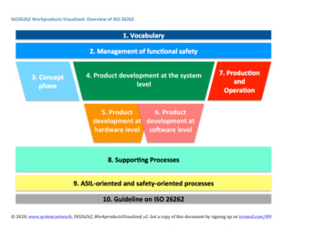
ISO 26262 Reading recommendation part 1, Vocabularypart 2, Management of functionalsafetypart 3, Concept phasepart 4, Product development: systemlevelpart 5, Product development: HW levelpart 6, Product development: SW levelpart 7, Production and operationpart 8, Supporting processespart 9, Safety analysespart 10, GuidelinePart 11, Semiconductor Guideline*Part 12, Adaptation for Motor cycles** New to 2nd edition recommended; optionalPUBLIC15
Scope of ISO 26262 ISO 26262 addresses Safety-relatedsystems including one or more E/E systems installed in series productionroad vehicles (except Mopeds) with a maximum gross weight up to 3500 Kg*. ISO 26262 does not address uniqueE/E systems in special purpose vehicles such as vehicles designed for driverswith disabilitiesFor Vehicles (and their components) released for production prior to the publication date ofISO 26262: Proven in use concept allows continued use of existing systems, sub-systems andcomponents only if no changes are made to the implementation* Weight restriction will be removed in 2nd editionPUBLIC16
Safety LifecycleIEC 61508ISO 26262PUBLIC17
ISO 26262 Key Differences from IEC 61508 ISO 26262 aligns with auto industry use cases and definition of acceptable risk IEC 61508 concept of safety function is replaced with ISO 26262 safety goals. Safetyfunction concept was based on the idea of defining a system under control and then“bolting-on” risk reduction measures Safety goal concept requires that risk reduction be part of the initial control system design Typical IEC 61508 systems are installed and then validated in place. ISO 26262 systemsmust be validated before release to market. ISO 26262 standard clearly defines work products for each requirement. This makesdetermination of compliance easier but limits flexibility of development system definition. ISO 26262 has hazard and risk analysis, failure rates and metrics adapted for Automotiveuse cases.PUBLIC18
03.Safety Integrity LevelsClassification of functional safety productsPUBLIC19
Determining ISO 26262 ASIL Level To determine the ASIL level of a system a Risk Assessment must be performed forall Hazards identified.Risk is comprised of three components: Severity, Exposure & ControllabilityS SeverityClassC ControllabilityDescriptionClassDescriptionS0No injuriesC0Controllable in generalS1Light and moderate injuriesC1Simply controllableS2Severe and life-threatening injuries (survival probable)C2Normally controllableS3Life-threatening injuries (survival uncertain), fatal injuriesC3Difficult to control or uncontrollableE ExposureClassDescriptionE0IncredibleE1Very low probabilityE2Low probabilityE3Medium probabilityE4High probabilityAccidentCausal Factor1HazardCausal FactornRisk S x (E * C)Safety Goal1Safety GoalnPUBLIC20
ASIL Determination TableRisk Severity x (Exposure * Controllability)ControllabilitySeverityS1Light and moderate injuriesS2Severe and life-threateninginjuries (survival probable)ExposureC1SimplyC2 NormalC3 DifficultE1 Very LowQMQMQME2 LowQMQMQME3 MediumQMQMASIL AE4 HighQMASIL AASIL BE1 Very LowQMQMQME2 LowQMQMASIL AE3 MediumQMASIL AASIL BASIL AASIL BASIL CE1 Very LowQMQMASIL AE2 LowQMASIL AASIL BE3 MediumASIL AASIL BASIL CE4 HighASIL BASIL CASIL DE4 HighS3Life-threatening injuries(survival uncertain), fatalinjuriesPUBLIC21
Automotive Application Safety levels (e.g.)SubsystemADAS – Vision/RadarAirbagsAlternatorBody Control ModuleBrake System (ABS, ESC, Boost)Collision Warning Cruise ControlDrowsiness MonitorE-Call / TelematicsFuel PumpEngine Oil PumpElectric MirrorsElectrochromatic MirrorsEngine ControlLightingNight VisionPower Door, Liftgate, Roof, TrunkRain Sense WipersSteering (EPS)Throttle ControlTire Pressure WarningTransmissionTransmission Oil PumpWindow LiftASIL Safety LevelB-DDC-DA-BA-D A-BA-DA-BA-BBBA-BA-BB-DA-BA-BA-BA-BD-D A-DA-BB-DB-CA-B Many applications that don’t have strict safetyrequirements today may have them in thefuture.For example, SAE is providing guidelines fordetermining ASILs. Applying these guidelineswill mean that auto apps that haven’t been“safety” to-date could be held subject toISO26262.Carmakers who require conformance will opena market window for safety-capable supplierslike NXP.PUBLIC22
Safety – ISO26262 DecompositionDecomposition is morerelevant at the system levelvs. component levelAchieve an ASIL level with QM products It is possible to achieve an ASIL level by developing a subsystem of multiple components which achieves the ASIL level as a whole.Decomposition redundantly assigns the same safety requirement to twoindependent and diverse elements.ASIL B ASIL A ASIL AASIL B ASIL B QM Enables the use of lower rated ASIL or QM products (from a systematic integritypoint of view). Key Point: Decomposition makes it possible to use components that achieve lowerASIL independently.Way to achieve Fault Metrics IO must be handled / checked by ASIL product Decision must be made / checked by ASIL product QM product must be TS-16949PUBLIC23
IEC 61508 Terminology for Safety Systems Low demand mode safety functions are required to operate at low frequencies,typically once or so per year. High demand mode safety functions are required to operate at high frequencies,typically many times per hour Continuous demand mode safety functions operate continuously. Hardware Fault Tolerance (HFT) is the number of faults that can occur withoutfailure of the safety function. HFT 0 requires redundancy. Safe Failure Fraction (SFF) is the ratio of safe and dangerous (but detected)failures in a system safety function to the total failure ratePUBLIC24
Determining IEC 61508 SILLikelihoodDefinitionRange (failures/year)CategoryDefinitionFrequentMany times in system lifetime 10 3CatastrophicMultiple loss of lifeProbableSeveral times in system lifetime10 3 to 10 4CriticalLoss of a single lifeOccasionalOnce in system lifetime10 4 to 10 5MarginalMajor injuries to one or more personsRemoteUnlikely in system lifetime10 5 to 10 6NegligibleMinor injuries at worstImprobableVery unlikely to occur10 6IncredibleCannot believe that it could occur 10 7to10 V Class I: Unacceptable in any circumstance Class II: Undesirable, tolerable only if risk reductionis impracticable or if the costs are grosslydisproportionate to the improvement gained Class III: Tolerable if the cost of risk reductionwould exceed the improvement Class IV: Acceptable as it stands, though it mayneed to be monitoredPUBLIC25
SIL Requirements Low demand functions have lessstringent requirements on PFDavg toachieve a specific SIL. High demand and continuousdemand functions have morestringent requirements on PFH toachieve a specific SIL. Process and machinery applicationsmix low and high demand functions. Transportation applications aretypically high demand.PUBLIC26
Determination of SIL based on HFT and SFF Type A products are simple products in which allfailure modes are known Type B products are complex products in whichall failure modes are not known (e.g.semiconductor). Hardware Fault Tolerance (HFT) is the numberof faults that can occur without failure of thesafety function. HFT 0 requires redundancy. Safe Failure Fraction (SFF) is defined as theratio of safe and dangerous (but detected)failures in a system safety function to the totalfailure rate SFF is calculated at element (component) orsystem level for a safety function. It should not beapplied for sub-elements.PUBLIC27
ISO 26262 vs IEC 61508 Safety Integrity Levels ISO 26262 was developed to meet automotiveindustry specific needs as replacement for IEC61508.IEC 61508 defines 4 safety integrity levels(SIL1,2,3,4)ISO26262 defines a Quality Managed level inaddition to 4 safety integrity levels (ASILA,B,C,D)ISO 26262ASIL LevelsIEC 61508SIL LevelsQuality Managed1A2B3C4DQMThere is no direct correlation betweenIEC61508 SIL and ISO 26262 ASIL levelsPUBLIC28
04.HardwareExpectations established on hardware development and productsPUBLIC29
ISO 26262 Failure RatesHardware Failure ModesFailure Rate λNon Safety RelatedSafety RelatedSafe FaultSafe Faultλ λSPF λRF λMPF λSDetectedMultiplePoint FaultPerceivedMultiplePoint FaultLatentMultiplePoint FaultResidual /SinglePoint FaultλSPF – Single Point FaultsλRF– Residual FaultsλMPFDP – Detected/Perceived Multi Point FaultsλMPFL – Latent Multi Point FaultsλMPF – λMPFDP λMPFL Multi Point Faults*λS– Safe Faults* multiple-point fault is an individual fault that, in combination with other independent faults, leads to a multiple-point failurePUBLIC30
ISO 26262 Fault MetricsMinimize single point and residual faults. Detectedand handled by system within system safety response time.MetricASIL BASIL CASIL DSingle point fault metricMinimize latent multi point faults. Detected and handled within hours through test algorithms.MetricASIL BASIL CASIL DLatent fault metricPUBLIC3131
IEC 61508 Failure RatesFailure Rate λ λS – Safe failure rate Noimpact on safety function λSD – Safe detected failure rate λSU – Safe undetected failure rate λD – Dangerous failure rate Impacton safety function λDD – Dangerous detected failure rate λDU – Dangerous undetected failure rateλ λS λD (λSD λSU) (λDD λDU)FIT Failures In Time 1 failure in 109 device hoursPUBLIC3232
IEC 61508 Safe Failure Fraction & SIL DeterminationSafe Failure Fraction (SFF) 1 –λDUλHigh Demand SystemHardware Fault Tolerance 0 (single channel)1 Fault may lead to loss of safety function.EX: 1oo1, 1oo1D, 2oo2 Hardware Fault Tolerance 1 (redundant)2 or more faults needed to loss of safety function.2oo3, 4oo5 Hardware Fault ToleranceSafe Failure Fraction(High Demand System)HFT 0HFT 10 60%-SIL160% 90%SIL1SIL290% 99%SIL2SIL3 99%SIL3SIL4PUBLIC33
05.SoftwareExpectations established on software development and productsPUBLIC34
Software component developmentSoftware failures are consideredto be systematicIEC 61508ISO 26262PUBLIC35
Coding guidelines and design principlesIEC 61508ISO 26262PUBLIC36
Software error detection and handlingIEC 61508ISO 26262PUBLIC37
06.ToolsExpectations established on software development toolsPUBLIC38
Tool Confidence Level Part 8: 11. Confidence in the use of software tools 11.4.5: Evaluation of a software tool by analysisISO 26262 DetermineTool Impact (TI)if a software tool can introduce or fail to detect errors in a safety-related TI1: No impact TI2: Impact Determine TD1: HIGH probability of detecting/preventing potential tool errors TD2: MEDIUM probability of detecting/preventing potential tool errors TD3: All other cases (LOW/unknown) Determine Tool Detection (TD) in usage of toolthe Tool Confidence Level (TCL)11.4.6: Qualification of a software tool TCL1:no qualification needed TCL2,TCL3:qualification according to tablesPUBLIC39
Requirements for Software Tools and Programming LanguagesIEC 61508PUBLIC40
07.Customer documentsSupporting documentation NXP provides to our customers to help in functional safety compliant developmentPUBLIC41
NXP SafeAssure ProductsTo support the customer to build a safety system, the following deliverablesare provided as standard for all ISO 26262 developed products. Public Information available via NXP Website Quality CertificatesSafety Manual* (HW and SW)Reference ManualData SheetConfidential Information available under NDA Safety PlanISO 26262 Safety Case (HW and SW)Permanent Failure Rate data (Die & Package) - IEC/TR 62380 or SN29500Transient Failure Rate data (Die) - JEDEC Standard JESD89Safety Analysis (FMEDA*, DFA) & ReportSW FMEA and Test ReportsPPAPConfirmation Measures Report (summary of all applicable confirmation measures)* includes IEC 61508 relevant dataPUBLIC42
08.What’s nextISO 26262 is going through a revision that will be incorporated into the next revision ISO 26262:2018PUBLIC43
ISO 26262:2018 Overall the 2018 ISO 26262 is an incremental improvement Very little new content towards fail operational / autonomousvehicles indicating not yet mature enough in industry tostandardizeMinor references to address interaction of Safety & SecurityNew content in current draft (ISO 26262:2016) Scope now for series production road vehicles, except mopeds. Specific content added for Trucks, Buses, Trailers, Semitrailersand motorcycles (although very minimal) Part 11 guideline added for Semiconductors Part 12 added for motorcycles (mapping of MSIL to ASIL) Interaction between safety and security organizations mentioned(no specifics) Method for dependent failure analysis provided in multipleexamples Guidance for fault tolerance Biggest impacts for NXP Part 2 changes for confirmation measures Part 8.13 changes for evaluation of hardware elements Part 11 guideline for SemiconductorsWhen do we implement 2018 content changes 25% already implemented 50% during BCaM7 (deploying in 2017) 25% in 2018PUBLIC44
NXP and the NXP logo are trademarks of NXP B.V. All other product or service names are the property of their respective owners. 2017 NXP B.V.
PUBLIC 3 What is functional Safety? ISO 26262 Definition: Absence of unacceptable risk due to hazards caused by mal-functional behavior of electrical and/or electronic systems and the interactions of these systems IEC 61508 Definition: Safety is the freedom from unacceptable risk of physical injury or of damage to the health of people, either directly, or indirectly as a result .