Transcription
Qualifying Dependent Failure Analysis within ISO26262: Applicability to SemiconductorsAlison Young, Alastair WalkerFunctional Safety ConsultantsLORIT CONSULTANCY, .walker@lorit-consultancy.comAbstractIn early 2018, the second edition of ISO 26262:2018[1] functional safety standard for road vehicles,was released.One of the main challenges in safety analysis is the decision on suitability of dependent failures. Manydiscussions ensue on the suitability and the potential impact of any common cause or dependent failures. ISO 26262 parts 9 and 11 give guidance of the categories of dependent failures initiators, but howto gauge acceptability is not so easily quantified.There is a lot of excellent literature on calculating failure rates for common causes, but this informationmay not easily support design teams in assessing the dependency of the 7 groups of dependent failure initiators listed in ISO 26262-9:2018.IEC 61508 uses a grading system based on a series of questions, however it relates any score gainedto the beta factors used in calculating failure rates. Ultimately it is desirable for dependent failuresanalysis to produce a quantitative result, but not one that feeds into failure rates, as many decisionsbased on failure rates involve software or system level considerations and are systematic rather thanrandom.One other significant factor in the dependent failures analysis is that many products being assessedagainst ISO 26262 were not originally designed to meet the standard, and are being adapted to comply. In this case an assessment of additional safety mechanisms and the quality of them is key.This paper proposes a quantitative approach to grade dependent failures analyses such that an acceptability criterion can be defined for different ASILs.KeywordsFunctional safety, dependent failures analysis (DFA), common cause failuresEuroSPI 2018 - 1.1
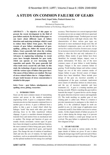
Session I: Session title will be inserted by editors1 IntroductionMany design teams in the automotive industry working to ISO 26262 implement the requirements ofparts 4, 5 and 6 of the standard to the letter of the law. The activities defined in part 9 such as DFAhowever are both trickier to define down to the limited amount of available information. The DFA likethe dependent failures initiator (DFI) identification in ISO 26262 is good, but how to actually definewhat is or is not acceptable is a trickier question.In ISO 26262 there are two defined goals for the DFA activities1. Identify single events, single causes & failure modes2. Identify safety measures to mitigate dependent failuresFor point a. above identifying the events is typically a straight forward activity but deciding that theimpact is or is not acceptable is more difficult.By defining a weighting system based on the type of dependence between the components permits agrading system of acceptability to be defined and hence whether the dependency is permissible in thegiven project.Equally for point b. a weighting system can be used for any safety measure to define the necessaryeffectiveness and quality of the mechanism.Techniques can be equally applicable to discrete or semiconductor components. Dependent failureanalysis on a single silicon die looks for interdependencies between hardware elements on the samedie, or between hardware and software elements. Typically, analysis focuses on hardware elementsperforming a safety function and their safety mechanisms.2 Dependent failure analysis2.1Dependent failure initiatorsDependent failure analysis typically begins with identification of pairs – usually a hardware elementand its safety mechanism. The scope of the analysis should be defined at the outset, and may includesafety mechanisms implemented in hardware, software, or both.Following the methodology recommended by Faller[2], each of the pairs in this list are then examinedto determine if:- A potential dependent failure would impact the safety function- No test exists for the potential dependent failure of the hardware element and safety mechanism- No safety measures exist to control or mitigate the effects of the dependent failure.If the answer for these three questions is positive then the pair should be included in dependent failureanalysis. The next step is to examine potential root causes of a dependent failure, these are termedDependent Failure Initiators (DFI) in ISO26262-9:2018.ISO26262-9: Annex C describes 7 groups of dependent failures initiators (DFI), these are representedin Figure 1 below. This annex also lists typical examples of DFI for each of the 7 categories, and mapsthe categories to the topics in ISO26262-9:2018 clause 7.4.4 and those described along with relatedmitigation measures in the Guideline on application of ISO26262 to semiconductors in ISO2626211:2018 clause 4.7.5.1.2 - EuroSPI 2018
Session I: Session title will be inserted by editorsFigure 1 ISO26262-9:2018 Dependent Failure InitiatorsWhen analysing dependent failures within a semiconductor device there will be some dependent failure initiators that can influence a large portion of the device, for example shared resources such ascommon clocks and shared power supplies. It is often possible to address these dependencies withinstandard safety analysis. Dependent failure analysis focuses on the dependent failure initiators thatcannot be addressed in standard safety analysis.One particular challenge when performing analysis on semiconductors is choosing pairs of components and initiators that have the greatest potential impact, and having confidence that the breadth ofthe analysis is sufficient. A weighting system that helps prioritise the key functions and initiators thatcan influence them is therefore very useful.2.2Common Cause Failure Analysis2.2.1 IEC61508 Strategy for Common Cause Failure AnalysisTo enable the calculation of beta factors for common cause analysis in IEC 61508[3] a series of 37questions are used to estimate the common cause frailties of the system in question. These questionsare split into the following categories: Separation Diversity/Redundancy Complexity/Design/Use/experience Judgment/analysis of data Procedures/usage Competence/Training/Safety culture Monitoring the surrounding conditions Test and environment.From the results of these 37 questions a weighted value results, this result determines the beta factorused in scaling the failure in time rates.2.2.2 Controller StrategyEuroSPI 2018 - 1.3
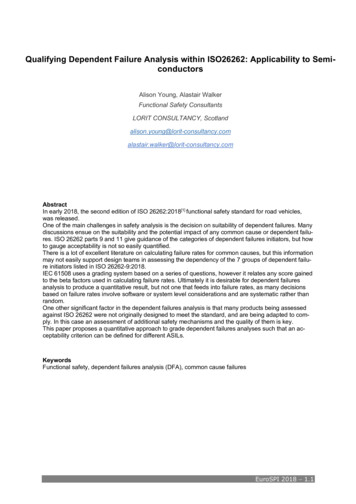
Session I: Session title will be inserted by editorsThere are many different controller architectures [4] available to support functional safety relevant projects – symmetric, asymmetric and multicore processers. The pros and cons of the different types inrelation to common cause failures is also well documented.Figure 2 Symmetrical and Asymmetrical Controller Strategies2.3Inherent good design against safety mechanism.In the cases where an existing product is being assessed for suitability to comply with ISO 26262 thearchitecture may not have been designed in accordance with ISO 26262. In these cases risk controlmeasures may need to be added to the architectureThe risk management standard ISO 14971[5] for medical devices recommends 3 techniques for reducing risk. The first is inherent good design, the second risk control measures and lastly the use of accompanying documents. The last option would not be applicable for the automotive industry, howeverif we use scaling factors for safety mechanisms these risk control mechanisms can be graded for thereduction they can make to the DFA grading score.3 Proposed Strategy3.1Dependent Failure Initiator GradingA scoring system for acceptance of DFI impacting a new design could be typically defined as below.The categories are those listed in ISO 26262-9:2018 Annex C, but this is not an exhaustive list, thereare others that will be applicable for any given projectDFI GroupShared ResourcesDFI TypeClockPower SupplyCommon Software1.4 - EuroSPI 2018DetailSame clock source for both channels nochecksTest only for stuck at faultsTest for stuck at, jitter, DC, driftFull independent clock monitoringIdentical Power SupplySame technology but different PSU implementationDifferent power supply technologyDifferent power supply technology, with independent monitoring, level, transient and oscillationIdentical software componentDifferent provider same functionalityScore1074110741107
Session I: Session title will be inserted by editorsSame silicon packageShared Information InputsSystem or HW -externalphysical signalsSoftware global variablesDFI GroupEnvironmentalInfluencesDFI TypeMechanical shockWater ingressEMCTransient upsetsSystematicCouplingSame algorithmsDifferent provider similar functionality differenthardwareDifferent SW implementationIntended function and safety measure in thesame silicon package – no monitoringIntended function and safety measure in thesame silicon package – single level of internalmonitoringIntended function and safety measure in thesame silicon package – single level of externalmonitoringIntended function and safety measure in thesame silicon package – multiple levels of external monitoringIdentical data handling of the signalsDiverse handling through the same interfaceDiverse handling through different interfaceDiverse handling through a different interfacewith independent monitoringHigh number of global variablesMinimal number of global variablesMinimal number of global variables EDC-ECCMinimal number of global variables EDC-ECC,full static analysis, control and data flowDetailDesigned to meet the mechanical requirementsDesigned and tested to meet all mechanicalrequirements (one sample)Designed and tested to meet all mechanicalrequirements (multiple samples)Designed and tested to exceed all mechanical requirements (multiple samples)Not designed to specified IP ratingDesigned to meet IP rating requirementsDesigned tested to meet IP rating requirements and expected servicing and service lifeDesigned tested to exceed IP rating requirements and expected servicing and service lifeDesigned to meet all emission and immunitylevels (not tested in all scenarios)Designed and tested to meet all emission andimmunity levels (one sample)Designed and tested to meet all emission andimmunity levels (multiple samples)Designed and tested to exceed all emissionand immunity levels (multiple samples)No testing of transient immunityDesign principles to minimise transient impactTransient testing of devices e.g. JEDEC 89Full confirmation of devices to ISO 26262 fortransient metrics. ECC for memoryIdenticalSame function different processorSame function different 1107411074EuroSPI 2018 - 1.5
Session I: Session title will be inserted by editorsConnection technologyComponents ofIdentical TypeIdentical hardwareIdentical software librariesCommunicationDFI GroupUnintendedImpactFailure of the physicallayer of the communication.SW Exchange of information.Failure of the applicationor protocol layer of thecommunications.DFI TypeHW CrosstalkThermal impactSW Timing and executione.g.Repetition of informationLoss of informationDelay of informationInsertion of informationMasquerade or incorrectaddressing of informationIncorrect sequence of informationCorruption of informationAsymmetric information sent tomultiple receiversInformation from a sender received by only a subset of receiversBlocking access to a communications channelSW Memory e.g.Corruption of contentInconsistent dataStack overflow or underflowRead or write access to memory1.6 - EuroSPI 2018Different function different implementationDesigned to meet the requirementsDesigned and tested to meet all requirements(one sample)Designed and tested to meet all requirements(multiple samples)Designed and tested to exceed all requirements (multiple samples)IdenticalSame function different software controlSimilar functional different software controlIndependent monitoring of resultsIdenticalSame function different hardware platformSimilar functional different hardware platformIndependent monitoring of resultsMinimal checks on data integrityTime-outs, message counters, CRC checksFull end to end ECC1107Full end to end ECC with external confirmation1DetailNo consideration connection impedanceBasic matching of impedancesFull evaluation of impedance and terminationFull evaluation of impedance, termination andphysical locationBasic design analysisDesign analysis and test per requirementsDesign and analysis of overstressed levels,thermal analysis (one sample)Design and analysis of overstressed levels,thermal analysis (multiple samples)Minimal checks on data s, message counters, CRC checks7Full end to end ECC4Full end to end ECC with external confirmation1Basic defensive design10Full static analysis7Full static analysis data & control flow4
Session I: Session title will be inserted by editorsallocated to another softwareelementFull static analysis data & control flow. ECC1Training of developmentand QA personnelBasic design trainingAll training by certified bodiesAll personnel at least 5 years functional safetyexperience trained by certified bodiesAll personnel at least 5 years functional safetyexperience trained by certified bodies. All holdfunctional safety qualifications and similar e.g.AutomotiveSPICEBasic or no trainingAll personnel trained on the specific projectAll personnel trained to certified qualificationsand on multiple projectsAll personnel trained to certified qualificationsand on multiple projects. Servicing inspectedby colleagues1074Training of service personnel3.2110741Additional Safety Mechanism GradingIf we take the example of a lack of inherent good design or a device developed prior to considerationof ISO 26262 requirements, then the addition of a safety mechanism can also be given a weightingfactor to determine quantitively the acceptability of the functionality combined with safety mechanism.The guidelines would follow those of section 3.1 above again comparing the safety mechanism to theintended functionality to determine the independence.4 Acceptable OutcomesThe acceptable outcomes from the grading system can be applied based on the ASIL of the safetygoal.e.g. for ASIL D the total score must be lower than 40 with the caveat that no single category score canexceed 4. ASIL C should be less than 80 and ASIL B should be lower than 120Again, the categories in section 3.1 are not exhaustive and if additional categories are added, then theacceptance limits can be scaled up accordingly5 ConclusionsISO 26262:2018 provides a good framework for design teams to develop compliant products and those that offer satisfactory levels of functional safety. However, the analysis of dependent failures andthat of common cause failures often leaves more questions that it provides answers. The lack ofguidance to design teams on what is an acceptable level for DFA is an issue that many organisationsfind difficult to answer.Much of the theory on common cause failures focuses on hardware failures, but considering the competence of service personnel is a far harder question to judge.In this paper we propose a solution based on the ideals of IEC 61508, but not aligning the outcomeswith beta factors, in this case giving criterion on how one can accept or reject a given level of dependent failure.6 Future workEuroSPI 2018 - 1.7
Session I: Session title will be inserted by editorsLorit Consultancy is working to enhance this approach to DFA and further document the strategy inorder to support customers in ISO 26262 DFA activities, in both semiconductor devices and discretecomponent design.1.8 - EuroSPI 2018
Session I: Session title will be inserted by editorsLiterature[1] – ISO DIS 26262:2018 Road vehicles – Functional safety[2] - Specification of a Software Common Cause Analysis Method”, Rainier Faller, pp 162 – 171, SAFECOMP2007. Springer-Verlag 2007.[3] – IEC 61508:2010 Functional safety of electrical/electronic/programmable electronic safety-related systems[4] – Controller Integrity in Automotive Failsafe System Architectures – Padma Sundaram and Joseph G.D’Ambrosio, Delphi Corporation. SAE Technical Paper Series 2006-010840.[5] – ISO 14971 Medical Devices- Application of risk management to Medical DevicesEuroSPI 2018 - 1.9
Session I: Session title will be inserted by editors7 Author CVsAlison YoungAlison has 15 years’ automotive industry experience, and for the last 6 years has beenresponsible for ensuring the functional safety of automotive microcontrollers. She hasbeen involved in the development of microcontrollers for a variety of automotive applications and has extensive experience of delivering the work products required by ISO26262, including requirements capture, safety plan, safety case, FMEDA and customerfacing safety documentation.Alastair WalkerAlastair Walker is an engineer with over 25 years’ development experience in medical,automotive and aviation industries. He is a TÜV Rheinland Functional Safety Engineer hehas been working as a functional safety consultant for 5 years and has extensiveknowledge of developing embedded systems in safety related industries, such automotivedrive train, in-wheel motors and battery management systems.1.10 - EuroSPI 2018
In early 2018, the second edition of ISO 26262:2018[1] functional safety standard for road vehicles, was released. One of the main challenges in safety analysis is the decision on suitability of dependent failures. Many discussions ensue on the suitability and the potential impact of any common cause or dependent failu-