Transcription
dbokSEBlueSolar Grid Inverter1500 / 2302000 / 2302800 / 2304000 / 2305000 / 230Manual
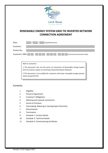
Before you startThis manual contains important information regarding installation and safe operation of this unit. Please read this manualcarefully before use.The BlueSolar grid-tied solar inverters are professional products that need to be installed by qualified personnel only. Pleaseread the safety instructions for more information.Inside the inverter very high voltages are present which are dangerous for life.If you encounter any problems during installation or operation of this unit, first check this manual before contacting your localdealer or a Victron energy representative. Instructions inside this manual will help you solve most installation and operationdifficulties.1. ContentBlueSolar 1500, 2000 and 2800 overviewFront ViewBottom ViewLCD DisplayShowing the inverters statusOperation LEDSolar panel inputRS2322Utility (AC) Connector
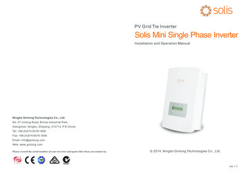
BlueSolar 4000 and 5000 overviewENFRDEESFront ViewBottom ViewOperation LEDITLCD DisplayShowing the inverters statusSEAppendixRS232Utility (AC) connectorOpening the packageAfter opening the package, please check the contents of the box. It should contain the following items:ItemNameQuantity123456BlueSolar inverterMounting frameMounting screwsSafety-lock screwsAC socket assemblyInstruction manual1142113
2. INSTALLATION2.1 Safety instructionsThe solar panels and cables should have Protection Class-II.Never connect the solar input of the inverter to a non-insulatedpower supply and simultaneously to the grid.If a non-insulated power supply is used to power the inverter forconfiguration purposes, DO NOT connect the inverter to the grid:this will cause serious damage to the inveter.When connected to a Victron MultiPlus or Quattro, please keep in mind that the Multi orQuattro cannot charge batteries at a higher rate than its nameplate charge current.A Multi 48/3000/35, for example can charge at max. 35A, which translates to a max. chargepower of 48 x 35 1680 WDo not disconnect the DC-cables when the inverter is connected to the utility mains!DC arcs will damage the connectors and could lead to serious burns and risk of fire.Qualified personnel must install the inverter.This inverter should be connected to a separate fuse in the breaker-box. No other householddevices should be connected to this.Do not open the inverter!High voltages inside the inverter are dangerous for life.Even after the unit is disconnected from the grid and photovoltaic panels, high voltages may stillexist inside the PV-inverter.Some parts and surfaces of the Inverter can become hot during operation. To reduce the risk ofinjury, do not touch the heat sink at the back of the PV-Inverter or nearby surfaces while Inverter isoperating.Do not install the inverter near explosive vapors or flammable items.(This unit is designed for outdoor usage IP65.Do not expose the inverter to direct sunlight.Direct sunlight increases the internal temperature which may reduce conversion efficiency.Do not expose the inverter to rain.Direct exposure to rain may, in course of time, increase humidity in the product, and ultimately resultin failure.4
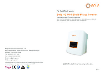
B.The inverter uses natural convection for cooling. Allow at least 20cm space above, below and on the sides of theinverter.C.Using the mounting frame as a template, drill 4 holes as illustrated in the following figures.D.Fix the mounting frame to the wall with the 4 screws.E.Hang the inverter on the mounting frame.F.Insert the safety-lock screws to the bottom leg to secure the inverter.DESelect a wall or solid vertical surface that can support the inverter.FRA.EN2.2 Mounting instructionsESITSEAppendix5
G. Check the mounting of the inverter securely by trying to raise it from the bottom.The inverter should remain firmly attached.When the mounting is done, the inverter can be connected.2.3 Connecting the inverter to the public gridA.Install a separate AC-line on a dedicated breaker from the breaker-box to the solar-inverter.No other appliances should be connected to this line!Open the breaker or fuse to disconnect power from the line.B.Connect a mains-cable to the AC-plug as described below:male insert withcoupling ring shellPressingscrew capInsert ac-wire through the pressing screw-cap and the shell. Connect wires according to polarities indicated onterminal block. L LINE (brown or black), N Neutral (blue) and G system ground (yellow-green).Fasten the gland plate with attached screws.Twist the gland so that the cable is firmly fixed.Insert Line wire to Pin L, Neutral wire to Pin N and Ground wire to Pin G.Pin GPin NPin L6AC wire
Recommended wire size for AC wireBueSolar 1500BueSolar 2000BueSolar 2800BueSolar 4000BueSolar 50001.502.502.504.004.00FR2Minimum wire size (mm )ENModelDEC.Connect the mains-cable to the inverter.D.Connect the mains-cable to the dedicated power outlet.ESDo not close the circuit breaker or fuse while working on the inverter.ITSE2.4 Connecting the inverter to the photovoltaic panelsA. The connectors from the photovoltaic panels should be MC4 (Multi-Contact 4mmAppendixWhen more than one PV-string is connected to the inverter(for the 2800, 4000 and 5000W) models, make sure thestrings are identical. The total open circuit voltage and shortcircuit current must be equal.Connecting these plugs to the solar-cables requires special tooling, and should only be done by qualified personnel.Improper connection can cause fire.Most solar panels have these connectors already attached to the cables.B. The voltage from the photovoltaic panels should never exceed the maximum input voltage of the inverter.Blue Solar 1500: The open circuit voltage of the solar array (Voc) should never exceed450V under any condition!Blue Solar 2000 and 2800: Voc should never exceed 500V under any condition!Blue Solar 4000 and 5000: Voc should never exceed 550V under any condition!The inverter will be permanently damaged if the Voc is too high.Notice that the Voc is at its highest when the solar-panels are at the lowest localtemperature that can be xpected, and do not carry current (inverter unplugged frompublic grid), with maximum sunlight (1000W/m2).7
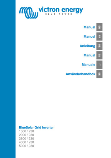
C. Verify if the polarity of the DC-plugs is correct. Incorrect polarity connection could permanently damage the unit.D. Connect the positive and negative terminals from the PV panel to positive ( ) terminals and negative (-) terminals on theinverter. The maximum current rating of DC terminals is 20A.Verify that the short-circuit-current of the solar array is below the maximum DC inputcurrent of the inverter.The inverter will not draw more current form the panels than I PV max (seespecification). If more current is available from the panels, the inverter will not consumethis extra current / power. The total system power will be lower then expected.2.5 System start-upWhen the PV panels are connected and their output voltage is greater than 100 VDC but the AC grid is not yet connected, themessage on the LCD display produces the following messages: “MODEL XkW”- “Waiting” - “Disconnect grid”. The displayrepeats “Disconnect grid” and the red LED “Fault” turns on.Close the AC breaker or fuse between PV-Inverter and grid.If the mains-voltage and frequency are within limits, a countdown will start (visible on the display).When the countdown has reached 0s, the inverter will connect to the grid and deliver energy.The LCD displays “Pac xxxx.xW”, which is the power fed into the grid. The green LED will be on indicating a normal condition.2.6 System DiagramInverter connected toseparate circuit breaker8
EN3. MODES OF OPERATIONThere are 5 different modes of operation.FRStandby modeIf the voltage from the photovoltaic panels is 100VDC the inverter has just enough power to start-up the internal controller, butthe voltage is too low to start energy conversion.ESNormal modeIn this mode the inverter works normally. Whenever the voltage from PV panel is sufficient (voltage 150VDC), the inverterconverts power into the grid. In normal mode the green LED is on.ITFault modeThe internal controller continuously monitor the system status. In case of unexpected conditions such as grid problems or aninternal failure, it will display the information on its LCD-display and light up the red “Fault” LED.SEShutdown modeDuring periods of little or no sunlight, the inverter automatically stops. The display and LED’s on the front panel do not work.AppendixStarting-up display sequence: Once the PV power is sufficient, the inverter displays information as follows:“User: xxxx” “Spec:xxxx” “Model:x.xkW” “SW Version :xx.xx” “Checking xxS” “Normal State” “Pac xxx.x W”.The LCD display backlight automatically turns off after 30 seconds to save power.LCD displayThe first line of LCDStateWait StateNormal StateAuto Test StateFault StatePermanent StateProgram StateThe second line of LCDCycle displayUser: xxxxSpec: xxxxModel:x.xkWSW Version:xx.xxEtotal: xxxkWhEtoday: xx.xkWhTtoday:xxhxxminPV:xxxV BUS:xxxVAC:xxxV xx.xHzDisplay contentWaitingChecking xxSReconnect in xxSStandbyPac xxxx.x WAuto testingSystem xx FaultInverter xx DamagedProgramingDisplay time /s111122222DEWaiting modeWhen the voltage from the photovoltaic panels is 100VDC, the inverter enters a “waiting-state” and attempts to connect to thegrid.RemarkInitial waitingSystem checkingSystem checkingPV voltage lowInverter output powerProtection auto testSystem faultInverter faultUpdate softwareRemarkThe user typeThe inverter spec typeThe inverter modelThe software versionThe energy totalThe energy todayOperation hours todayThe PV and Bus voltageThe Grid voltage and frequency9
4. TROUBLE SHOOTINGIn case of a malfunction/system failure, the red (Fault) LED on the front panel turns on and the LCD displays the cause of theproblem.Please refer to the following table for a list of all possible LCD-warnings.Warning:Explanation:Grid V FaultThe utility mains voltage is too high or too lowCheck the mains-voltage on the display.Wait for 5 minutes. If the grid voltage returns to normal the inverter will automatically restart.Action:If the voltage increases and becomes too high when the inverter is starting up, it possibly means thatthe mains-connection has too much resistance, or has bad connections.It is possible to monitor the mains-voltage with the data-logging software supplied with your inverter.A mains-voltage that increases with more then 10V when the inverter goes from 0W to full outputpower indicates a high impedant mains network.Warning:If the problem persists, call an electrician.Grid F FaultExplanation:The utility mains frequency is too high or too lowAction:Check the mains-frequency on the display.Wait for 5 minutes. If the grid frequency returns to normal the inverter will automatically restart.If the mains-frequency remains outside the limits of this inverter, call an electrician.Disconnected gridWarning:Explanation:Action:There is no mains-voltage present on the inverter.Check if the fuse or circuit -breaker for the solar-inverter in the circuit breaker-box is closed. If thecircuit breaker or fuse is closed call service.Warning:High PV VoltageExplanation:The voltage coming from the solar-panels is too high.Warning:Check the value on the LCD which refers to the PV-voltage, (PV:xxxV).If this value is close to or more then the value in the specification referred to as “Max input voltage”,open the circuit-breaker and then remove all cables from the PV-inverter immediately! Call service.Your PV-inverter will be damaged if no action is taken.High TemperatureExplanation:The temperature of the inverter is too high.Action:Warning:Check if the ambient temperature of the inverter is not too high. Check if the inverter is mountedaccording to the specification, and that there is sufficient room around the inverter for convection.Check if the black cooling bracket behind the inverter is clean and has no obstructions.If the problem persists, call service.Not ConsistentExplanation:Action:The 2 micro controllers in the inverter have contradicting data.Call service.Warning:Eeprom damagedExplanation:Action:The Eeprom memory in the inverter is damaged.Call service.Warning:Low IsolationAction:Explanation:Action:10During start-up of the inverter, the inverter measures the electrical isolation between the solar-panelsto protective earth / ground. If the isolation is insufficient, the inverter will not start up to prevent anunsafe situation.Open the circuit breaker, and then disconnect the DC-plugs from the inverter for 5 minutes. After 5minutes reconnect DC-plugs and close AC breaker.
The inverter has not been initiated for the first time in the factory.Call serviceWarning:GFCI DamagedExplanation:Action:The GFCI-protection unit is damaged.Call serviceWarning:Sensor DamagedExplanation:Action:The DC current sensor in the inverter is damaged.Call serviceSCI damagedExplanation:Action:The communication between the two micro controllers in the inverter has failed.Call h DC INJNormally the inverter injects AC-current into the public grid. When the warning “high DC INJ” is on,for some reason the injection of DC-current into the grid is higher then acceptable, and the invertershuts :ESWarning:Open the circuit breaker, and then disconnect the DC-plugs from the inverter for 5 minutes. After 5minutes reconnect DC-plugs and close AC breaker.If the problem persists, call service.Please InitiateDEAction:FRHigh ground IThe GFCI (Ground Fault Current Interrupter) is active due to a fault current from live parts to theearth. The inverter will shut down.ENWarning:Explanation:Open the circuit breaker, and then disconnect the DC-plugs from the inverter for 5 minutes. After 5minutes reconnect DC-plugs and close AC breaker.If the problem persists, call service.High Bus VoltageThe internal BUS-voltage is too high.Open the circuit breaker, and then disconnect the DC-plugs from the inverter for 5 minutes. After 5minutes reconnect only the DC-plugs (do not close the n:Warning:Explanation:Action:Is the warning “High Bus Voltage” visible on the display?Yes the voltage from the solar panels is too high, or there is an internal failure (Call service).No close the circuit-breaker and wait for the inverter to reconnect to the grid. If the “High BusVoltage”-warning comes back again after reconnecting to the grid, there is probably something wrongwith the grid. (Call an electrician).Relay DamagedThe internal relays used for connecting the inverter to the grid are damaged.Open the circuit breaker.Call serviceAuto test failedThe self-test of the inverter has failed. There is an internal failure.Warning:Open the circuit breaker, and then disconnect the DC-plugs from the inverter for 5 minutes. After 5minutes reconnect DC-plugs and close AC breaker.If the problem persists, call service.2.5V Ref FaultExplanation:Action:The internal voltage reference of the inverter is defect.Call service.Warning:There is nothing visible on the display.Explanation:Action:The display power is coming from the solar panels.Check if the DC-plugs are firmly connected to the inverter. If there is sufficient daylight and the LCDdoes not give any indication / value call service.11
5. SPECIFICATIONSBlueSolar Grid InverterGRID OUTPUT (AC)Nominal output powerMaximum output powerNominal output currentMaximum output currentMaximum fuse protectionHarmonic distortion of output currentNominal AC output voltagePower factorOperating AC voltage rangeNominal AC frequencyOperating AC frequency rangeInternal consumption at nightShort circuit proofSOLAR INPUT (DC)Maximum Input voltageInput Voltage MPPT rangeMaximum input currentMaximum input powerNumber of MPPT trackersNumber of stringsStart-up powerGround fault monitoringReverse polarity protectionEFFICIENCYMaximum efficiencyEuropean standard efficiencyGENERALTopologyCommunication portOperating temperature rangeNominal power temperature rangeStorage temperature rangeMaximum operating altitudeCooling methodRelative humidityENCLOSUREProtection degreeDC connectorsWeight (kg)Dimensions (hxwxd, mm))STANDARDSSafetyEMC, EmissionEMC, ImmunityEMC, Harmonics and FlickerAutomatic Grid .5A13A19A16A16A25A 3% at nominal power 5% at 50% power220V - 230V - 240V 0,99% at nominal power190-260V50Hz45.5-54.5Hz 160W4500W1111247W7W10WRCMU (residual current monitoring unit)Yes, with short circuit -20 C to 60 C (automatic power limit in case of internal over temperature)-20 C to 55 C-20 C to 70 C2000 m (5% derating at 4000 m)Natural convectionMax 95%14.8 kg376x415x125IP54MC4 (Multi Contact 4mm)14.8 kg14.8 kg20.7 kg376x415x125376x415x125368x475x195EN 50178EN 61000-6-3EN 61000-6-2EN 61000-3-2, EN 61000-3-3VDE 0126-1-120.7 kg368x475x195
Avant de commencerFRLes convertisseurs solaires BlueSolar raccordés au réseau sont des produits professionnels qui ne doivent être installés quepar du personnel qualifié. Veuillez lire les instructions de sécurité pour de plus amples informations.ENCe manuel contient des informations importantes relatives à l'installation et au fonctionnement en toute sécurité de cette unité.Veuillez lire ce manuel avec attention avant de commencer l'utilisation.Des tensions très élevées, présentant un danger mortel, se trouvent à l'intérieur du convertisseur.DESi vous rencontrez des problèmes quelconques pendant l'installation et le fonctionnement de cette unité, vérifiez d'abord cemanuel avant de contacter votre fournisseur local ou un représentant de Victron Energy. Les instructions contenues dans cemanuel vous aideront à résoudre la plupart des difficultés d'installation et de fonctionnement.ES1. ContenuVue d'ensemble BlueSolar 1500, 2000 et 2800ITSEAppendixVue de faceVue de dessousLED defonctionnementÉcran LCDMontre les états desconvertisseursEntrée panneausolaireConnecteur électrique (CA)RS2321
Vue d'ensemble BlueSolar 4000 et 5000Vue de faceVue de dessousÉcran LCDMontre les états desconvertisseursLED defonctionnementConnecteur électrique(CA)RS232Ouverture du colisAprès l'ouverture du colis, veuillez en vérifier le contenu. Vous devez y trouver les articles suivants :2ArticleNomQuantité123456Convertisseur BlueSolarCadre de montageVis de montageVis de verrou de sécuritéEnsemble de prise CAManuel d'instructions114211
2. INSTALLATIONEN2.1 Instructions de sécuritéFRLes câbles et panneaux solaires doivent disposer de la classe de protection 2DEESNe jamais connecter l'entrée solaire du convertisseur à unealimentation non isolée et simultanément au réseau.Si une alimentation non isolée est utilisée pour mettre en route leconvertisseur à des fins de configuration, NE JAMAIS connecter leconvertisseur au réseau : cela causerait des dommagesirréversibles au convertisseur.ITSEAppendixLorsqu'il est connecté à un Multi ou Quattro de Victron, n'oubliez pas que ce Multi ouQuattro ne peut pas charger des batteries à un taux supérieur à celui de son courant decharge indiqué sur sa plaque signalétique.Un Multi 48/3000/35 peut par exemple charger à un maximum de 35 A, ce qui équivaut à unepuissance de charge maximale de power of 48 x 35 1680 WNe pas déconnecter les câbles CC quand le convertisseur est connecté au réseau électrique !Des arcs CC endommageront les connecteurs et ils pourront entraîner de sérieuses brûlures ainsique des risques d'incendie.Seul du personnel qualifié doit installer le convertisseur.Ce convertisseur devra être raccordé à un fusible à part dans la boîte des disjoncteurs. Aucunautre appareil électroménager ne doit y être raccordé.Ne pas ouvrir le convertisseur !Les tensions élevées à l'intérieur du convertisseur peuvent être mortelles.Même après avoir déconnecté l'unité du réseau et des panneaux photovoltaïques, il peut persisterde tensions élevées dans le convertisseur PV.Certaines pièces et surfaces du Convertisseur peuvent se chauffer pendant le fonctionnement.Pour réduire les risques de blessures, ne touchez pas le radiateur se trouvant derrière leconvertisseur PV ou près des surfaces pendant le fonctionnement du convertisseur.3
N'installez pas le convertisseur près de vapeurs explosives ou d'éléments inflammables.(IP65.Cette unité est conçue pour une utilisation extérieureNe pas exposer le convertisseur à la lumière directe du soleil.L'ensoleillement direct augmente la température interne, ce qui peut réduire l'efficacité de laconversion.Ne pas exposer le convertisseur à la pluie.L'exposition à la pluie peut augmenter l'humidité à l'intérieur du produit au fil du temps, etfinalement provoquer une défaillance.4
EN2.2 Instructions de montageB.Le convertisseur utilise un système de refroidissement par convection naturelle. Laissez au moins 20 cm d'espace audessus, dessous et sur les côtés duconvertisseur.C.En utilisant le cadre de montage comme modèle, percez 4 trous comme il est indiqué sur les schémas suivants.D.Fixez le cadre de montage au mur avec 4 vis.E.Accrochez le convertisseur sur le cadre de montage.F.Insérez les vis de verrou de sécurité sur la partie inférieure pour sécuriser le convertisseur.DEChoisir un mur ou une surface verticale solide qui peut supporter le convertisseur.FRA.ESITSEAppendix5
G. Vérifiez que le convertisseur est solidement monté en essayant de l'élever depuis le bas.Le convertisseur devra être fermement fixé.Quand le montage est terminé, le convertisseur peut être connecté.2.3 Connecter le convertisseur au réseau électriqueC.Installez une ligne CA séparée sur un disjoncteur spécifique depuis la boîte du disjoncteur vers le convertisseursolaire.Ne pas raccorder d'autres appareils sur cette ligne!Ouvrez le disjoncteur ou le fusible pour déconnecter la puissance de la ligne.D.Raccordez un câble réseau à la prise CA, comme il est décrit ci-après :prise mâle aveccollier deserrage Culot à visdouilleCâbleCAInsérez le câble CA à travers le culot à vis de pression et la douille. Connectez les câbles conformément auxpolarités indiquées sur le bloc de jonction. L LIGNE (marron ou noir), N Neutre (bleu) et G système masse(jaune - vert).Fixez la plaque de presse étoupe avec des vis de fixation.Vissez la plaque de manière à ce que le câble soit fermement fixé.Insérez le câble de Ligne à la broche L, le câble Neutre à la broche N et le câble de masse à la broche G.BrocheGBrocheNBrocheL6
Taille de câble recommandée pour un câble CABueSolar 1500BueSolar 2000BueSolar 2800BueSolar 4000BueSolar 50001,502,502,504,004,00FR2Taille de câble minimale (mm )ENModèleDEConnectez le câble de réseau au convertisseur.D.Connectez le câble de réseau à la sortie de puissance spécifique.ESC.ITNe fermez pas le disjoncteur ou le fusible pendant le fonctionnement du convertisseur.SE2.4 Connecter le convertisseur aux panneaux photovoltaïquesA. Les connecteurs des panneaux photovoltaïques doivent être MC4 (Multi-Contact 4 mmAppendixSi plus d'une série PV est connectée aux modèles deconvertisseur (pour les 2800, 4000 et 5000 W), assurezvous qu'elles soient identiques. La tension totale du circuitouvert et le courant de court-circuit doivent être égaux.La connexion de ces prises aux câbles solaires doit être réalisée avec des outils spéciaux et par du personnel qualifié.Une connexion incorrecte peut provoquer des incendies.La plupart des panneaux solaires disposent de ces connecteurs déjà attachés aux câbles.B. La tension des panneaux photovoltaïques ne doit jamais dépasser la tension d'entrée maximale du convertisseur.Blue Solar 1500 : Sous aucun prétexte, la tension de circuit ouvert du dispositif solaire(Voc) ne doit dépasser 450 V !Blue Solar 2000 et 2800 : La Voc ne doit dépasser 500 V sous aucun prétexte !Blue Solar 4000 et 5000 : La Voc ne doit dépasser 550 V sous aucun prétexte !Le convertisseur sera endommagé de façon permanente si la Voc est trop élevée.Notez que la Voc est à son niveau le plus élevé quand les panneaux solaires sont à latempérature locale la plus basse qui peut être espérée, et qu'ils ne transportent aucuncourant (convertisseur débranché du réseau électrique), avec un ensoleillementmaximal (1000 W/m2).7
C. Vérifiez si la polarité des prises CC est correcte. Une connexion de polarité incorrecte peut endommager l'unité de façonpermanente.D. Connectez les bornes positive et négative du panneau PV aux bornes positives ( ) et aux bornes négatives (-) sur leconvertisseur. La puissance de courant nominal maximale des bornes CC est de 20 A.Vérifiez que le courant de court-circuit du dispositif solaire est en dessous du courantd'entrée CC maximal du convertisseur.Le convertisseur ne tirera pas plus de courant des panneaux que le maximum I PV (voirspécification). Si plus de courant est disponible depuis les panneaux, le convertisseurne consommera pas ce courant/puissance extra. La puissance totale du système serainférieure à celle attendue.2.5 Démarrage du systèmeQuand les panneaux PV sont connectés et leur tension de sortie est supérieure à 100 VCC, mais le réseau CA n'est pasencore connecté, le message de l'écran LCD affiche les messages suivants : “MODÈLE XkW”- “En attente” - “Réseaudéconnecté”. L'affichage répète "Déconnectez le réseau" et la LED rouge "Erreur" s'allume.Fermez le disjoncteur ou le fusible CA entre le convertisseur PC et le réseau.Si la tension et la fréquence du réseau se trouvent dans les limites, un compte à rebours démarrera (visible sur l'écran).Quand le compte à rebours a atteint 0 s, le convertisseur se connectera au réseau et il délivrera l'énergie.La LCD affiche “Pac xxxx.xW” qui correspond à l'énergie transmise dans le réseau. La LED verte sera allumée, indiquant desconditions normales.2.6 Schéma du systèmeConvertisseur connecté à undisjoncteur séparé8
EN3. MODES DE FONCTIONNEMENTIl y a 5 modes de fonctionnement différents.FRMode PauseESMode attenteQuand la tension des panneaux photovoltaïques est 100 VCC, le convertisseur passe en "état-attente" et il essaie de seconnecter au réseau.ITMode normalSous ce mode, le convertisseur fonctionne normalement. Si la tension du panneau PV est suffisante (tension 150 VCC), leconvertisseur convertie la puissance dans le réseau. En mode normal, la LED verte est allumée.SEMode ErreurLe contrôleur interne surveille continuellement l'état du système. En cas de conditions anormales, comme les problèmes deréseau ou de défaillance interne, il affichera l'information sur son écran LCD et la LED rouge "Erreur" s'allumera.AppendixMode arrêtPendant les périodes faiblement ou pas du tout ensoleillées, le convertisseur s'arrêtera automatiquement. L'écran et les LEDsur le devant du panneau ne marchent pas.Séquence d'affichage du démarrage : Une fois que la puissance PV est suffisante, le convertisseur affichera les informationssuivantes :“Utilisateur : xxxx” “Spéc:xxxx” “Modèle :x.xkW” “SW Version :xx.xx” “Vérification xxS” “État Normal” “Pac xxx.x W”.L'écran LCD de rétroéclairage s'éteindra automatiquement après 30 secondes pour économiser de l'énergie.Écran LCDLa première ligne du LCDÉtatÉtat attenteÉtat normalÉtat test automatiqueÉtat ErreurÉtat permanentÉtat programmeLa seconde ligne du LCDÉcran de cycleUser: xxxxSpéc : xxxxModèl:x.xkWSW Version:xx.xxEtotal : xxxkWhEtoday : xx.xkWhTtoday:xxhxxminPV :xxxV BUS :xxxVAC:xxxV xx.xHzContenu affichageAttenteVérification xxSReconnexion en xxSAttentePac xxxx.x WTest automatiqueErreur xx SystèmeConvertisseur xx EndommagéEn cours de programmationAffichage temps /s111122222DESi la tension des panneaux photovoltaïques est 100 VCC, le convertisseur dispose de la puissance suffisante pour démarrerle contrôleur interne, mais la tension est trop faible pour démarrer la conversion d'énergie.RemarqueAttente initialeVérification du systèmeVérification du systèmeTension PV réduitePuissance de sortie convertisseurTest automatique protectionErreur systèmeErreur convertisseurMise à jour logicielRemarqueType d'utilisateurLe type spéc. de convertisseurLe modèle du convertisseurLa version du logicielL'énergie totaleL'énergie d'aujourd'huiHeures de fonctionnement aujourd'huiLa tension PV et BusLa tension et fréquence de réseau9
4. RÉSOLUTION DE PROBLÊMESEn cas de défaut de fonctionnement/ défaillance du système, la LED rouge (Erreur) sur le panneau frontal s'allume et l'écranLCD affiche la cause du problème.Veuillez consulter le tableau suivant pour la liste de tous les avertissements possibles sur l'écran LCD.Attention :Grid V Fault (erreur de tension du réseau)Explication :La tension du réseau électrique est trop haute ou trop basse.Vérifiez la tension du réseau sur l'écran.Attendez 5 minutes. Si la tension du réseau redevient normale, le convertisseur redémarreraautomatiquement.Mesure :Si la tension augmente et devient trop élevée pendant le démarrage du convertisseur, cela peutvouloir dire que la connexion au réseau offre trop de résistance, ou que les raccordements sontmauvais.Il est possible de surveiller la tension du réseau avec un logiciel d'enregistrement de données fourniavec votre convertisseur. Une tension de réseau qui augmente de plus de 10 V quand leconvertisseur passe de 0 W à la pleine puissance de sortie, indique un réseau électrique ayant uneimpédance élevée.Attention :Explication :Mesure :Attention :Explication :Mesure :Attention :Explication :Grid F FaultLa fréquence du réseau électrique est trop haute ou trop basse.Vérifiez la fréquence du réseau sur l'écran.Attendez 5 minutes. Si la fréquence du réseau redevient normale, le convertisseur redémarreraautomatiquement.Si la fréquence du réseau ne se trouve toujours pas dans les limites de ce convertisseur, appelez unélectri
When the voltage from the photovoltaic panels is 100VDC, the inverter enters a "waiting-state" and attempts to connect to the grid. Normal mode In this mode the inverter works normally. Whenever the voltage from PV panel is sufficient (voltage 150VDC), the inverter converts power into the grid. In normal mode the green LED is on. Fault mode

![Welcome [s3-ap-southeast-2.amazonaws ]](/img/28/wmi5140-user-manual.jpg)