Transcription
Saleae User Guide 1.1.15Logic & Logic16 User’s GuideHello, and thanks for using Logic. We hope this guide will answer any questions you might have, but ifnot please do let us know at support@saleae.comWarning: Using Logic or Logic16 to test equipment powered by AC MAINs power can be hazardous toequipment. Battery‐powered, wall‐wart powered, and USB powered equipment is generally safe. Foranything else please make sure to read the section Safety and Equipment Protection.Happy Debugging!ContentsLogic & Logic16 User’s Guide . 1Installing the Software . 3Installation on Windows & Mac . 3Installation on Linux . 3Using the Hardware . 4Connecting the wire harness . 4Logic16 Wire harnesses . 4Test Clips . 4Connecting directly to IDE headers. 4Disconnect Logic from your circuit when the USB is unplugged . 4Safety and Equipment Protection . 4Using the Software. 6Quick Tips . 6Using the Trigger . 6Navigating the data display. 61Copyright 2012 Saleae LLC. All Rights Reserved.
Saleae User Guide 1.1.15Timing Measurements . 7Placing Timing Markers . 8Saving and Opening a Session . 8Exporting Data . 8Saving Screenshots. 10Selecting the Display Radix (i.e. Hex, Decimal, etc.) . 10Using Protocol Analyzers . 11Hiding, un‐hiding, and reordering channels . 12Resetting the trigger, channel names, channel ordering and channel visibility . 12Hiding the channel labels and/or trigger . 13Working with tabs . 13Switching between multiple Saleae logic analyzers . 15Changing the Logic16 channels . 16Crosstalk (and Logic16 input voltage selection) . 17Saleae Community Site . 19SDKs – Device SDK and Analyzer SDK. 19Forum . 19Beta software releases . 19Data Integrity . 20Maximum Sample Rate . 20Maximum sample rate, and long captures – Logic16 . 21Safety and Equipment Protection . 22Contacting Us . 232Copyright 2012 Saleae LLC. All Rights Reserved.
Saleae User Guide 1.1.15Installing the SoftwareInstallation on Windows & MacDownload the latest version from our site, here: http://www.saleae.com/downloads. Double click &install like any other application.Note: Windows XP Users: Please download the 32‐bit version of the software.Note: Vista & Windows 7 Users: Please download the either 32‐bit or 64‐bit installation depending onyour version of Windows. You can find out by right‐clicking Computer in the start menu, and choosingProperties.OS X Tiger Users: The application needs to be unzipped before it can be installed.Installation on Linux1. Download the latest version from our site, here: here: http://www.saleae.com/downloads.2. There is no installer, you can unzip the application anywhere you like, perhaps your homefolder, or your desktop. You can start using it on your desktop, and move it later if you like.3. Double click the Logic executable to start the program.4. If you like, make a link to the Logic application for your desktop or application menu or dock.5. Note that wherever you decide to put the logic application, it must all stay together in the samefolder structure, and it must have write permissions.6. When connecting to Logic, you may get a message from the application that it doesn’t havepermissions to connect to Logic. If this happens, run the install driver script in the application’sDriver folder.32‐bit vs. 64‐bit: Please choose the version appropriate for your Linux Distribution.64‐bit Users: Please note that as of 1.1.5, you won’t be able to load sessions saved with otherversions (platform distributions) of the Logic software. However, other Logic software distributionswill be able to load sessions that you save. Sorry for the trouble – we’ll get this fixed.3Copyright 2012 Saleae LLC. All Rights Reserved.
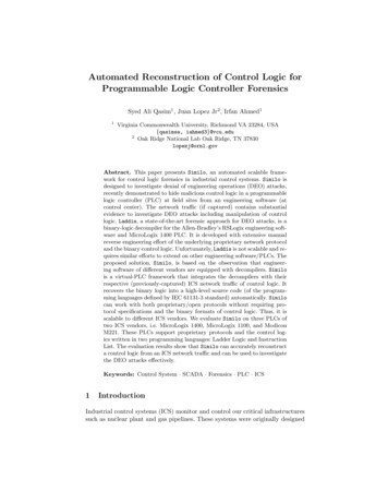
Saleae User Guide 1.1.15Using the HardwareConnecting the wire harnessTo determine the correct way of attaching the wire harness, look on the back of your device for theground symbol:Then find the gray wire on the wire harness. This is the ground wire. It will have a GROUND label nearits end:Logic16 Wire harnessesLogic16 uses two 9‐wire harnesses. On the bottom of the device, these are labeled A and B. A ischannels 0‐7, and B is channels 8‐15.Note that you don’t need to have both harnesses plugged in if you’re only using the first 8 channels.Test ClipsYou can connect your test leads (from the wire harness) to the provided test clips. They might requirequite a bit of force before they “click.”Connecting directly to IDE headersIn some situations, you will be able to plug the test leads directly into IDE headers on your PCB, whichcan be very convenient. For new PCB designs, we recommend including headers for things you mightneed to look at during firmware development. You only need to solder in the headers if you have anissue, and they can be removed in the final PCB revisions if needed. These will serve as nice test pointsfor an oscilloscope as well. Don’t forget to wire in some ground pins as well.Disconnect Logic from your circuit when the USB is unpluggedYou should disconnect Logic from your circuit when it is not connected to your computer. If Logic is notpowered by the USB, it can put a load on your circuit that can compromise signal integrity.Safety and Equipment ProtectionIn general, Logic and Logic16 may not be used with DUTs (devices under test) which are not electricallyisolated from MAINs (wall power). This is because the logic analyzer shares a common ground with yourcomputer, which typically is grounded with respect to MAINs earth ground. This creates a potential4Copyright 2012 Saleae LLC. All Rights Reserved.
Saleae User Guide 1.1.15short circuit path for any non‐isolated MAINs‐derived voltages, via the logic analyzer’s ground input(s).For more details, please refer to the section on Safety and Equipment Protection near the end of thisUser’s Guide.5Copyright 2012 Saleae LLC. All Rights Reserved.
Saleae User Guide 1.1.15Using the SoftwareQuick Tips Almost everything has tooltips that offer some explanation of what it does. Most functions have keyboard shortcuts, described in their menu item or their tool tip.Using the Trigger Tip: mouse‐over the trigger buttons for a description. The trigger looks for a single edge. To use the trigger, there must be one edge specified. You can also specify that other inputs must be in particular states (high or low) when the edgeoccurs. Pre‐trigger data will be collected for the region of time before the trigger is found (to the extentthe trigger is not immediately found). You can configure this amount under Options ‐ Preferences The time where the trigger is found is time zero in the display.Navigating the data display Click and drag the display to move it6Copyright 2012 Saleae LLC. All Rights Reserved.
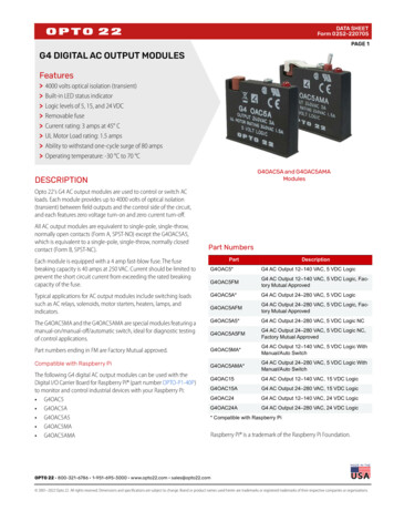
Saleae User Guide 1.1.15 Use the scroll wheel on your mouse to zoom in and outAlternatively, use the arrow keys to zoom and pan (The /‐ keys also zoom)To “jump to next,” move your mouse to, and click the button that will appear near at the ends ofthe graphs. You can use the keys N (next) and P (previous) as well. (this applies to the channelthat was last used by the mouse)Timing Measurements Tip: Move your mouse over each measurement label for a description. 7Width: The time between the selected two successive signal transitions.Period: The time elapsed between the selected three successive signal transitions.Frequency: The frequency computed by dividing one (1) by the time elapsed between theselected three successive signal transitions.Duty Cycle: The % of time the signal is high (1) during the selected three successive signaltransitions.Byte: The numerical representation of all 8 channels combined into one byte, at the specifiedlocation.T1: The absolute time specified by the location of the T1 timing marker.T2: The absolute time specified by the location of the T2 timing marker. T1 ‐ T2 : The time elapsed between the timing markers.To show or hide particular measurements, use the settings button.Copyright 2012 Saleae LLC. All Rights Reserved.
Saleae User Guide 1.1.15Placing Timing Markers Single‐click the T1 or T2 label. (or use 1 and 2 keys on your keyboard) Move your mouse to the desired location. Note that you can still pan and zoom. Single click to place the marker. Your mouse must not be moving when you place the marker. To move the marker after it has been placed, click it. To cancel placing a marker, right‐click or press the escape key.Saving and Opening a Session To save a session that includes data, press CTRL‐S (CMD‐S on a Mac) or select this function fromthe Options menu. To save a session that contains only settings, press CTRL‐SHIFT‐S (CMD‐SHIFT‐S on a Mac), orselect this function from the Options menu. To open a session of any type, drag it into the software, or press CTRL‐O (CMD‐O on a Mac), orselect this function from the Options menu.Exporting DataTo export data, select Options‐ Export Data (CTRL‐E).8Copyright 2012 Saleae LLC. All Rights Reserved.
Saleae User Guide 1.1.15 Channels to Export: Select which channels you would like to exportSamples to Export: Select the time period over which you would like to export sampleso Tip: If you are using timing markers, you can export just the data between them. Thisoption will only appear in the list if two timing markers have already been placed.Export Format – Binaryoo9You can select if you want data outputted for every sample, or only for samples that aredifferent than prior samples. Note that if you export only changes in the data, a 64‐bitsample number is written before each sample in the file.If you aren’t exporting all of the channels, you can choose to leave the bits in theiroriginal channel locations, or to have them shifted right to fill any unused positions.Copyright 2012 Saleae LLC. All Rights Reserved.
Saleae User Guide 1.1.15 o You can choose to export each sample as an 8, 16, 32, or 64‐bit word.Export Format – VCD o VCD stands for Value Change Dump, and is a common format for digital data.Export Format – CSVoooooChoose this format to export data as comma or tab delimited, human readable text.You can optionally include column headings for the dataYou can use sample number (i.e. 1, 2, 3, 4) or timestamps (i.e. .00123s ) to specify thetime a sample represents. This occupies the first column.You can combine all the channels into a single number, or you can export each bit in itsown column.You can export every sample, or only samples that have changed.Saving Screenshots You can take a screenshot of all or part of the application, and either save it to a file, or copy itto the clipboard. You can find this in the Options menu, or use the keyboard shortcuts.Selecting the Display Radix (i.e. Hex, Decimal, etc.) Use this Options menu item (or the keyboard shortcuts) to quickly toggle between the differentdisplay modes.10Copyright 2012 Saleae LLC. All Rights Reserved.
Saleae User Guide 1.1.15Using Protocol Analyzers To add a protocol analyzer, select one from the menu in the Analyzers panel. 11Protocol analyzers can share inputs with other analyzers. This can be useful in some cases, suchas SPI.After you add (or edit) an analyzer, it immediate runs against any data you have collected.To export data from an analyzer, press the small file icon next to it. (Center button).If you need to change the display format (radix) of a particular analyzer, you can do this from theAnalyzer settings menu.Copyright 2012 Saleae LLC. All Rights Reserved.
Saleae User Guide 1.1.15Hiding, un‐hiding, and reordering channelsYou can hide channels you aren’t using. (Note that this is different than turning off channels – which youcan do with Logic16 to increase sampling speed)Move your mouse over the channel label area of the screen. I drop down menu button will appear. Youcan Hide channels, Show (un‐hide) them, and Move (reorder) them.Resetting the trigger, channel names, channel ordering and channel visibilitySometimes you may want to start from a fresh slate, and you don’t want to do this one item at a time.Use the Reset option to do this.12Copyright 2012 Saleae LLC. All Rights Reserved.
Saleae User Guide 1.1.15Hiding the channel labels and/or triggerTo clear up additional screen space, you can optionally hide both the channel label and/or the trigger.Find this under the Options menu item.Working with tabsTabs let you save multiple captures, and switch between them.The Capture TabThe most important thing to know is that you can only capture new data from the Capture tab, which isthe small tab with the magnifying glass logo.13Copyright 2012 Saleae LLC. All Rights Reserved.
Saleae User Guide 1.1.15Adding new tabsAfter you collect data, the Capture Tab will change, adding a button to one side. Click this button tomove your new data into its own tab.Renaming a tabClick tab’s text to edit it. Note that a tab must be active before it can be edited.Press enter, or click outside the text area to stop editing.Reordering tabsYou can reorder tabs however you like, by dragging them.14Copyright 2012 Saleae LLC. All Rights Reserved.
Saleae User Guide 1.1.15Closing TabsYou can close tabs by using its menu. This can’t be undone, so be sure to save your session if you needto, before closing the tab.Copying settings between tabsOccasionally you may make changes on one tab you may wish to propagate to another tab. From thetab’s menu, choose Copy.For instance, if you set up some analyzers in one tab, and you wanted to run them against data in adifferent tab, you could copy them. Note that this will replace any analyzers that were already in thattab.Tabs, and saving your dataWhen you save your session, (Options‐ Save Session‐ settings & data) you are only saving the sessionassociated with the currently active tab. There isn’t a way (yet) to save all your tabs at the same time, orto save them all to a single file – a “session set”. We will be adding this capability in the future.Switching between multiple Saleae logic analyzersWhile there isn’t a way to collect from multiple Saleae logic analyzers at the same time, you can havemore than one connected to your computer, which can be helpful in some circumstances.If more than one logic analyzer is connected, the menu item Connected Devices item will appear in theOptions menu.15Copyright 2012 Saleae LLC. All Rights Reserved.
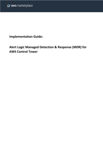
Saleae User Guide 1.1.15Changing the Logic16 channelsWith Logic16 you can select which channels to use – and if you need fewer channels you can sample athigher speeds. This setting is in the Options menu, under Logic16 channels. You can select from one ofthe standard options, or be more specific by choosing Select custom channels.16Copyright 2012 Saleae LLC. All Rights Reserved.
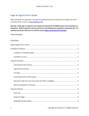
Saleae User Guide 1.1.15Crosstalk (and Logic16 input voltage selection)Logic16 has two voltage settings, one for 1.8V to 3.6V, and another for 3.6V to 5V.The lower voltage settings should work in most circumstances. The 5V setting is provided to reduce thelikelihood of channel to channel crosstalk when using 5V signals. Crosstalk is developed, at least in part,by Logic16’s long lead wires, fast rise/fall times, and is greatest when using 5V signals. Logic16’s frontend filters noise like this, but only up to a point. You should be able to have 8 different signalssimultaneously switch without seeing crosstalk on adjacent signals.17Copyright 2012 Saleae LLC. All Rights Reserved.
Saleae User Guide 1.1.15If you experience crosstalk, be sure both ground wires are connected to your circuit as this can make adramatic difference.Unconnected (floating) inputs are much more susceptible to crosstalk. You may want to turn off or hideunused signals. This applies to both Logic and Logic16.18Copyright 2012 Saleae LLC. All Rights Reserved.
Saleae User Guide 1.1.15Saleae Community SiteSDKs – Device SDK and Analyzer SDKWe have cross‐platform, c based SDKs for getting access to Logic or Logic16 at a low level, and formaking your own protocol analyzer plugins. You can get access to this SDK at our community site, atsaleae.com/community.ForumTo share ideas or issues, and to connect with other users, head over to the forum in the community site,at saleae.com/community.Beta software releasesWe occasionally have new software releases which we think are pretty good, but don’t want to riskdisrupting a large number of users if something in it needs fixing. Typically these releases turn out to bepretty stable and have additional features and fixes that the current release doesn’t have. If there areany beta releases, they’ll be on the community site.19Copyright 2012 Saleae LLC. All Rights Reserved.
Saleae User Guide 1.1.15Data IntegrityLogic and Logic16 may not be able to achieve a particular sample rate (see the next sections) but it willnever present data with samples missing. By design it stops and notifies you as soon as any data is lost.Maximum Sample RateGenerally speaking Logic is able to achieve sample rates of 24MHz when no other devices are on theUSB host, and your computer is responding sufficiently quickly. However if the USB is servicing otherdevices, or the computer is performing in a latent manner, a smaller sample rate, such as 16MHz or12MHz may be the fastest achievable. The reason for this is as follows:Logic uses USB 2.0, and uses the USB transfer type known as “Bulk”. While this transfer type has thelargest theoretical average bandwidth (significantly larger even than the 24 MB/s needed by Logic) italso has the lowest priority. This means it may be “bumped” for other USB traffic from other devices.The second issue is that Logic has very limited device‐side memory. Specifically it has x4 512 bytebuffers. These buffers must be emptied by the USB in such a way that they never all become full at thesame time. If this happens, the logic software will report that the sample rate could not be maintained.This means that even if on average (which would normally be the case) the USB can give Logic at least 24MB/s, it must not prioritize other devices on the USB for so much time that Logic’s small buffer wouldoverflow. For this reason Logic can’t guarantee that it will operate at its maximum 24MHz, as this iscontingent on a number of factors including computer performance, USB bandwidth availability andlatency, other drivers that may be using the USB, etc.To maximize the sample rate possible on your computer, try the following: 20Make sure that no other applications are consuming significant CPU time.Make sure you have enough free RAM so that the OS will not have swap ram to the hard drive.This will be too slow.Try connecting Logic directly to your computer instead of through a USB hub.Make sure other devices on the USB are minimally active. (i.e. not webcams, hard drives, etc.)Try disconnecting other peripherals from the USB, or switching Logic to a port serviced by adifferent host controller. You may even want to try a dedicated host controller, such as this onehttp://www.newegg.com/Product/Product.aspx?Item N82E16815166014Increase the process priority of the Logic software.o Windows: From the Windows Task Manager, select the Processes tab, and find the Logicprocess. Right click on this item and select Set Priority ‐ High.o Linux: From the command line, navigate to the folder where the Logic executable is.Type nice –n 3 ./Logic. Search for Linux nice on Google for more information.Copyright 2012 Saleae LLC. All Rights Reserved.
Saleae User Guide 1.1.15Maximum sample rate, and long captures – Logic16Logic16 has a significantly larger hardware‐side buffer than Logic, and therefore is much more immuneto latencies in the USB. It is also more likely than Logic to reliably operate at its maximum speed on agiven computer.If you need to capture for long periods of time, especially to catch “overnight” errors in the act, werecommend using Logic16.21Copyright 2012 Saleae LLC. All Rights Reserved.
Saleae User Guide 1.1.15Safety and Equipment ProtectionThe primary concern for safety and equipment protection is the ground return path. Logic’s (andLogic16’s) ground input is essentially shorted to the ground of your computer, and your computer’sground is likely connected to earth ground. Therefore Logic’s ground line has the potential to provide ahigh current ground return path to a device under test. This can result in the destruction of Logic, theUSB host, and in the worst case, the computer. Logic should not be used with DUTs (devices under test) which are not electrically isolatedfrom MAINS (i.e. wall power). There is one exception outlined below, but it comes withimportant caveats and must be fully understood. Please contact us if you have any concerns.o If you need to test a MAINs–connected DUT, one possible solution is to use a Laptop,running on battery power and not connected to anything else (such as a likely‐groundedLCD monitor). This will prevent Logic from providing a short circuit ground return path.HOWEVER – this setup introduces an additional and very serious safety concern. Thereason for the MAINs earth ground connection in the first place it to prevent a highvoltage from connecting to a chassis which could cause electric shock to a user. Agrounded chassis, if connected to a large voltage, will provide a short circuit, which thenblows a circuit breaker or fuse and removes the high voltage, protecting a user frompotential electrocution. If you use the workaround presented here, you must ensurethat it is impossible for any high voltage to be connected to any of Logic’s inputs, andespecially Logic’s ground lead. Low voltages (as measured relative to earth ground) –which would not present a risk of electric shock – are permissible.o Isolation transformers, such as those made by Tripp‐lite: These transformers provide alarge 1:1 transformer so that that the “hot” AC power lines are electrically isolated fromMAINS. However, and crucially, they DO NOT isolate the MAINs earth groundconnection, and so are not useful for providing a solution to this issue.DUTs which are battery powered, or USB powered (from the same computer as Logic) areacceptable.o When using USB powered DUTs, special care should be taken to avoid connecting USBsourced power to Logic's ground, as this provides a short‐circuit return path.DUTs powered by AC adapters which have only 2 prongs, and do not have an earth groundconnection (such as most "wall warts") usually provide MAINS isolated power and are generallyacceptable. They also are less likely to be able to source enough current to cause seriousdestruction. We highly recommending testing for good isolation.o If in any doubt as to if Logic’s ground ‐‐ and/or the ground of your DUT ‐‐ is isolatedfrom MAINs earth ground, use a Multimeter to measure the resistance to earth ground.At this time, there are no cost effective isolation products for 480Mbit USB (High Speed USB) that weare aware of. There are fiber optic based solutions that cost around 1000.22Copyright 2012 Saleae LLC. All Rights Reserved.
Saleae User Guide 1.1.15Contacting UsYou’re always welcome to contact us about anything. support@saleae.com is typically the best way toreach us, or online at http://www.saleae.com/contactWe’re more than happy to discuss any issue or questions you have via phone, too. The most reliabletime to reach us is in the afternoons and early evening (Pacific time). If you miss us, please do leave amessage and we’ll call you back. 510‐984‐246323Copyright 2012 Saleae LLC. All Rights Reserved.
3. Double click the Logic executable to start the program. 4. If you like, make a link to the Logic application for your desktop or application menu or dock. 5. Note that wherever you decide to put the logic application, it must all stay together in the same