Transcription
OPTI 222Mechanical Design in Optical EngineeringMohr's Circle for Plane StressAnalysis of Stress and Strain:As we learned in the previous two lectures, when a structural element is subjected toseveral types of loads acting simultaneously, say bending and torsion, principal stressesoccur. These stresses act on principal planes where the shear stresses are zero. Inaddition, many engineering problems, such as axial bars, beams in bending and circularmembers in torsion, are examples of a state of stress called plane stress (σz τzx τzy 0). Our procedure for determining principal stresses for a state of plane stress is asfollows:1. Determine the point on the body in which the principal stresses are to bedetermined.2. Treating the load cases independently and calculated the stresses for thepoint chosen. When applicable combine the stresses to determine the stateof stress at the point.3. Choose a set of x-y reference axes and draw a square element centered onthe axes.4. Identify the stresses σx, σy, and τxy τyx and list them with the properdirection.5. Calculate the principal stresses, the maximum shear stress and the principalplane if required.Principal Stresses (Shear Stress 0):σ1 σ2 σx σy2σx σy22 σx σ y 2 τ xy 2 2 σx σy 2 τ xy 2 Maximum Shear Stress:2τ max σx σy 2 τ xy 2 τ max σ1 σ 2982
OPTI 222Mechanical Design in Optical EngineeringPrincipal Planes (Planes on which Principal Stresses Act):2θ p tan 12τ xyσx σ yPlane of Maximum Shear Stress:2θ s tan 1 σx σ y2τ xyAverage Stress (Shear Stress is Maximum):σ avg σx σy2Important Observations:1. Principal stresses occur on mutually perpendicular planes.2. Shear stresses are zero on principal planes.3. Planes of maximum shear stress occur at 45 to the principal planes.4. The maximum shear stress is equal to one half the difference of the principalstresses.It should be noted that the equation for principal planes, 2θp, yields two angles between0 and 360 . Which one corresponds to σ1 and which to σ2? This can be determined bysubstituting one of the values into the stress transformation equation for normal stress.Normal Stress Transformationσn σx σy2 σx σy2cos 2θ τ xy sin 2θShear Stress Transformationτ nt (σ x σ y ) sin θ cosθ τ xy ( cos 2 θ sin 2 θ )99
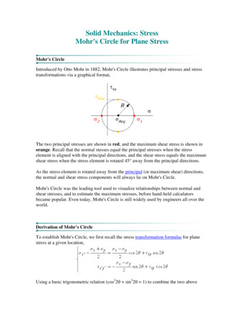
OPTI 222Mechanical Design in Optical EngineeringExample Problem:Determine:a) The principal planes.b) The principal stresses.c) The maximum shear stress and the corresponding normal stress.Mohr’s Circle for Plane Stress:The transformation equations for plane stress can be represented in a graphical formatknown as Mohr’s circle. This representation is useful in visualizing the relationshipsbetween normal and shear stresses acting on various inclined planes at a point in astressed body.Before we discuss the procedure for constructing Mohr’s circle there a several rules thatapply.Stress ComponentPlotNormal Stresses(Horizontal Axis) For Tension- For CompressionShear Stresses(Vertical Axis) For Clockwise Shear- For Counterclockwise Shear100
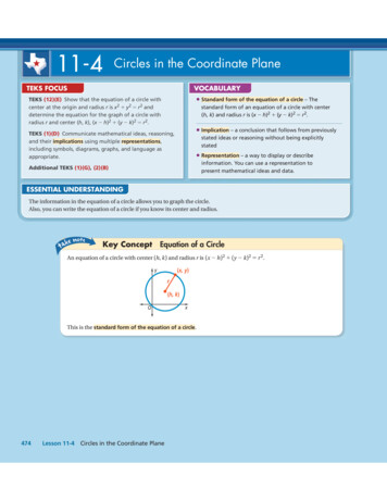
OPTI 222Mechanical Design in Optical EngineeringConstruct Mohr’s circle as follows:1. Determine the point on the body in which the principal stresses are to bedetermined.2. Treating the load cases independently and calculated the stresses for the pointchosen.3. Choose a set of x-y reference axes and draw a square element centered on theaxes.4. Identify the stresses σx, σy, and τxy τyx and list them with the proper sign.5. Draw a set of σ - τ coordinate axes with σ being positive to the right and τ beingpositive in the upward direction. Choose an appropriate scale for the each axis.6. Using the rules on the previous page, plot the stresses on the x face of theelement in this coordinate system (point V). Repeat the process for the y face(point H).7. Draw a line between the two point V and H. The point where this line crosses theσ axis establishes the center of the circle.8. Draw the complete circle.9. The line from the center of the circle to point V identifies the x axis or referenceaxis for angle measurements (i.e. θ 0).Note: The angle between the reference axis and the σ axis is equal to 2θp.Mohr’s Circle:101
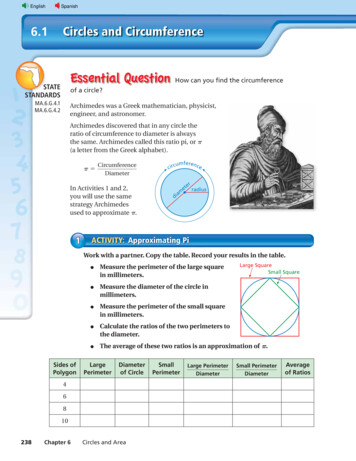
OPTI 222Mechanical Design in Optical EngineeringConsider the previous example.102
Construct Mohr's circle as follows: 1. Determine the point on the body in which the principal stresses are to be determined. 2. Treating the load cases independently and calculated the stresses for the point chosen. 3. Choose a set of x-y reference axes and draw a square element centered on the axes. 4. Identify the stresses σ x, σ y, and .