
Transcription
USER’S /DVRAD1620
INTRODUCTIONTHANK YOUWelcomeThank you for choosing First Alert for your security needs!For more than half a century, First Alert has made the home-safety and security products that makeyour job easier. Our products are built to the highest standard which has earned us a leadership rolein the home-safety and security product categories. We are committed to serving our customers,from the professionals who install our products, to the families and businesses who count on them.First Alert has been helping families and businesses stay safe for over 50 years. By having a FirstAlert Security System, you’re taking the first step in protecting your home or business from damageor theft. We’re watching, even when you’re not.This manual is written for the SmartBridge DVRAD0405/DVRAD0805/DVRAD0810/DVRAD1610/DVRAD1620 DVRs. It was accurate at the time it was completed. However, because of our ongoing effortto constantly improve our products, additional features and functions may have been added since thattime and on-screen displays may change. We encourage you to visit our website at www.firstalert.com orwww.brkelectronics.com to check for the latest manuals (English and Spanish), firmware updates, downloads,other security camera products and announcements. You’ll find this product line under Home Security Security Cameras Wired Cameras. 2013 BRK Brands, Inc. All rights reserved. Distributed by BRK Brands, Inc., Aurora, Illinois 60504. BRK Brands, Inc. is a subsidiary of JardenCorporation (NYSE: JAH). First Alert and SmartBridge are registered trademarks of the First Alert Trust. Due to continuing product development, the product inside the packaging may look slightly different than the one on the package. To obtain warranty service, contact the ConsumerAffairs Division at 1-800-323-9005, Monday through Friday, 7:30 a.m. - 5 p.m., Central Standard Time.Made in ChinaPage 2
INTRODUCTIONKEY PRODUCT FEATURESMain DescriptionFour, eight or sixteen channel H.264 digital video recorder with Internetremote surveillance, motion detection, PTZ and alarm control suitablefor applications such as high-end residential - new or remodel, lightcommercial, small business/retail, small warehouse or small groceryProduct Features Auto IP connection capability H.264 Compression & Virus free Linux O/S Record, playback, mobile phone live view, backup, control, & remote access 500 GB, 1 TB or 2TB SATA hard drive installed depending on model Supports smart phone live view User-friendly interface: DVR capable of providing 16 bit true color,semi-transparent GUI with notes for selected menu items. Advanced motion detection activated recording 24/7 Scheduled Recording Network monitoring through internet access Supports USB or external DVD backup Hi-speed backup/upgrade/record via USB2.0 PTZ camera control HDMI Video OutPage 3
INTRODUCTIONTABLE OF CONTENTSSection12DescriptionPage #IntroductionSafetyProduct Overview2-567What is in the Box7DVR Controls38-9Front Panel8Back Panel9Remote Control10Mouse and Virtual Keypad11Camera Power Connections12Connecting Devices12Initial Setup - System Operation13System Start Up13Power On/Off13Setup Wizard Setup Wizard4514System Setup 25System26-27Device28-29Basic Operation30View Layout30Video Adjust31PTZ (PAN TILT ZOOM) Camera32Clients33Snapshot34Record Setup35-37Playback38Clear Alarm39Shutdown39Page 4
INTRODUCTIONTABLE OF CONTENTSSectionDescriptionPage #Remote Access40Network Setup6840-42External Recording43External Playback44Settings45Advanced Setting46Pan Tilt Zoom47Setting Up Groups48Remote Configuration49Camera Settings50Appendix51Hard Drive Removal and Installation51Specifications52FAQ’s (Frequently Asked Questions)53Troubleshooting54Warranty55Page 5
SAFETYCAUTION STATEMENTSSafety Precautions Do not drop, puncture, or disassemblethe cameras or DVR.Do not tug on the power adapter. Use theplug to remove it from the wall.Do not expose the cameras or DVR to high temperatures. For your own safety, avoid using the DVR whenthere is a storm or lightning in your area.Use the cameras and DVR with care. Avoidpressing hard on the cameras or DVR body.Do not use power cable if it is damaged or crushed.Safety Precautions Instructions for Use Always purchase the correct size and grade ofbattery most suitable for the intended use. Replace all batteries of a set at the same time. Clean the battery contacts and also those ofthe device prior to battery installation. Ensure the batteries are installed correctlywith regard to polarity ( and -).Remove batteries from equipment that is notto be used for an extended period of time.Remove used batteries promptly.FCC ComplianceFCC Compliance Class B Digital DeviceThis equipment has been tested and found to comply with the limits for a Class B digital device, pursuant to Part 15 of the FCC rules. These limits aredesigned to provide reasonable protection against harmful interference in a residential installation. This equipment generates, uses and can radiate radiofrequency energy and, if not installed and used in accordance with the instructions, may cause harmful interference to radio communications.However, there is no guarantee that the interference will not occur in a particular installation. If this equipment does cause harmful interference to radio or television reception,which can be determined by turning the equipment off and on, the user is encouraged to try to correct the interference by one or more of the following measures: Reorient or relocate the receiving antenna.Increase the separation between the equipment and receiver.Connect the equipment into an outlet on a circuit different from that of the receiver.Consult the dealer or an experienced radio or TV technician for help.Notice: Only peripherals complying with FCC class B limits may be attached to this equipment. Operation with non-compliant peripherals orperipherals not recommended by First Alert / BRK Brands, Inc. is likely to result in interference to radio and TV reception. Changes or modificationsto the product, not expressly approved by First Alert / BRK Brands, Inc., could void the user’s authority to operate the equipment.Important: The information shown in the FCC Declaration of Conformity paragraph below is a requirement of the FCC and is intended to supply you with information regarding theFCC approval of this device. The phone number listed below is for FCC related questions only and not intended for questions regarding the connection or operation for this device.FCC Declaration of Conformity for devices with the FCC logo. Responsible Party: First Alert / BRK Brands, Inc., 3901 Liberty Street Rd., Aurora, IL. 605048122 Telephone: (630) 851 - 7330. Product / Model: DVRAD04, DVRAD08, and DVRAD16. We, First Alert / BRK Brands, Inc. declare under our sole responsibilitythat the device to which this declaration relates: Complies with Part 15 of the FCC Rules. Operation is subject to the following two conditions: (1) this device maynot cause harmful interference, and (2) this device must accept any interference received, including interference that may cause undesired operation.FCC Certification (if applicable)This device contains a radio transmitter. Accordingly, it has been certified as compliant with 47 CFR Part 15 of the FCCRules for intentional radiators. Products that contain a radio transmitter are labeled with an FCC ID.Fire and Electric Shock Hazard StatementThe lightning flash with arrowhead symbol, within an equilateral triangle,is intended to alert the user to the presence of un-insulated “dangerousvoltage” within the product’s enclosure that may be of sufficient magnitudeto constitute a risk of electric shock.CAUTIONRISK OF ELECTRIC SHOCKThe exclamation point within an equilateral triangle, is intended to alert theuser to the presence of important operating and maintenance (servicing)instructions in the literature accompanying the appliance.CAUTION: TO REDUCE THE RISK OF ELECTRIC SHOCK. UNPLUGALL POWER SOURCES, INCLUDING CAMERAS FROM THE DVRBEFORE REMOVING COVER. FAILURE TO DO SO CAN RESULT INDAMAGE TO THE DVR OR ITS COMPONENTS AS WELL AS INJURYOR DEATH.WARNING: TO PREVENT FIRE OR SHOCK HAZARD, DO NOTEXPOSE THIS DVR UNIT TO RAIN OR MOISTURECAUTION: TO PREVENT ELECTRIC SHOCK, MATCH WIDE BLADEOF THE PLUG TO THE WIDE SLOT AND FULLY INSERTDisposalCaution!When working with electrostatic sensitive devices such as hard disk or DVR unit, make sureyou use a static-free workstation. Any electrostatic energy coming in contact with the harddisk or DVR can damage it permanently.Page 6These symbols indicate that it is prohibitedto dispose of these batteries in thehousehold waste. Take spent batteries thatcan no longer be charged to the designatedcollection points in your community.
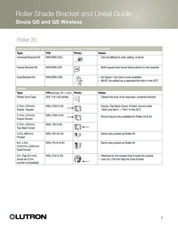
PRODUCT OVERVIEWPACKAGE CONTENTS,What s in the Box*H.264 4,8 or 16 channel Digital DVRwith 500 GB, 1 TB or 2TB Hard DriveDVRAD0405/DVRAD0805: 500 GBDVRAD0810/DVRAD1610: 1TBDVRAD1620: 2TBENGLISHDVR QUICK START GUIDEStep 4: Downloading the SmartBridge SoftwareStep 2: Connecting the Cameras / DVR1234Product Contents5Connect the BNC & power from camera with BNC power cable using the side labeled"Camera Side”Using other side of BNC power cable connect BNC to BNC video input on DVRConnect power cable to one of the multi power splitter endsPlug (red) connector on power splitter to 12V DC input on DVRPlug DVR power supply into wall outlet1234Insert install CD into CD Rom Drive Double click SmartBridge.exe or letCDRom run automatically.Install SmartBridge Software.On your computer desktop, Double click installed Smartbridge Software Icon.Select the Connect Tab. Enter Auto ID DVR Code (On DVR system, right click andselect “Net Status” to obtain Auto ID DVR Code). Password is default 123. SelectLogin to start viewing your Smartbridge security system remotely.WARNING1PowerMENU12341234BNC VIDEO & DC POWER CABLEIRRecESC(1 supplied with each camera)DVR2POWER SUPPLYDVR & CAMERASCAMERA(S)4(5 or 9-Way Power Splitter)315(Attach for each camera)REMOTE CONTROL &USB 2.0 MOUSERJ45 ETHERNET CABLESTICKERSPOWER SPLITTER FORDVR AND CAMERAS2THESE PREMISES ARE UNDER24 HOUR VIDEO SURVEILLANCEStep 3: Connecting your Mouse and Ethernet CableWARNINGTHESE PREMISES ARE UNDER24 HOUR VIDEO SURVEILLANCEPROTECTED BY(9 way supplied with 8 Camera systems;5 way supplied with 4 camera systems)12323Connect the USB mouse to the bottom USB slot on the backConnect the Ethernet cable to the back of the DVR labeled either NET or RJ45Connect the other end of the cable directly to your router, modem or high speedinternet connection input(Monitor Option)Connect a VGA cord (not included) from your monitor to the VGA Output port on the back of your DVR.(TV Option)Connect the end of the BNC-RCA (BNC SIDE ONLY) cable to the back of theDVR labeled “Video Output”Connect the BNC-RCA (RCA SIDE ONLY) cable to an open video (yellow RCA) input on your TV/Monitor(note the input name or number)Turn on your TV and select the appropriate input (noted above)3BACK of DVR211VGAPROTECTED BYBack of DVRiPhone, iPad, Android Compatible*2Go to firstalert.com and search for model # to find complete instruction manual ofyour First Alert DVR.1343Note: Please consult the networking section of your manual to configure the DVR forremote viewing.Step 1: Connect the DVR to your Monitor or TV11 2012 BRK Brands, Inc. All rights reserved. Distributed by BRK Brands, Inc., Aurora, Illinois60504. BRK Brands, Inc. is a subsidiary of Jarden Corporation (NYSE: JAH). First Alert is aregistered trademark of the First Alert Trust. Due to continuing product development, the productinside the packaging may look slightly different than the one on the package. To obtain warrantyservice, contact the Consumer Affairs Division at 1-800-323-9005, Monday through Friday, 7:30a.m. - 5 p.m., Central Standard Time.* iPhone and iPad are registered trademarks of Apple Inc. Android is a trademark of Google, Inc.www.firstalert.comQuick Install GuideInstallationSoftwareRJ45 Ethernet Cable9-way splitteror two splitters for 16channel60’ BNC Video &DC Power Cables(One for each camera. Varies with kits dependingon number of cameras included.)Power Supplyfor DVR3 WindowWarning DecalsRemote ControlPage 7USB 2.0 Mouse
PRODUCT OVERVIEWDVR CONTROLSFront Panel21278109114 Channel DVR18 Channel DVR2116 Channel DVR1Item123Function(1) IR remote receiverPower indicator lightRecord indicator lightButtons ptionDirect remote towards this position when using DVRA green light indicates power is onA green flashing light indicates recordingCamera Selection410 Press for camera selection of channels 10-16 (on 16 channel DVR only)5MenuEnter menu setup6ESCBrings system previous selection7LeftIn menu mode: moves to highlight next section8UpIn live mode: rotates between single , quad, eight or nine camera screen9DownIn live mode: rotates between single , quad, eight or nine camera screen10RightIn menu mode: moves to highlight previous section11OKPress to make selection12SleepOn 16 Channel DVR onlyPage 8
PRODUCT OVERVIEWDVR CONTROLSBack Panel4 Channel DVR101183128 Channel DVR1012111254763881312547681316 Channel DVR101112Item28315476813FunctionDescription1Alarm4 alarm inputs; 1 alarm output2VGA OutputFor connecting to VGA monitor3HDMI OutputFor connecting to HDMI monitor4USB/MouseUse Lower USB port for mouse connection; Use Upper USB port for USB flashdrive or backup5NETFor connecting RJ45 ethernet cable to PC or router6RS485For connecting PTZ cameras7Power SwitchPower On/Off8Power SupplyFor connection to power cord 12V DC9Audio InputFor connecting audio signal from audio capable cameras or self powered microphones (RCA jacks)10Video InputFor connecting video signal from cameras (BNC)11BNC OutputFor connecting to a BNC monitor12RCA Audio OutFor connecting to a speaker or amplifier13GroundGround ConnectionPage 9
PRODUCT OVERVIEWREMOTE CONTROLRemote Control1Remote Control OperationThe remote control is the secondary input device for navigating the system’s interface.In device operation, the MENU key has the same function as “left click” of the mouse.Item12FunctionDescriptionPowerClick power for about 3-5 seconds to shut down the DVR.29NumericPress to Select channel to view; use to input numerical information inButtonsappropriate screensNAVIGATION BUTTONS1178103Press to make selectionPress to cursor up; in PTZ mode, press to pan camera up3Press to move cursor down; in PTZ mode, press to pan camera down4Press to move cursor left; in PTZ mode, press to pan camera leftPress to move cursor right; in PTZ mode, press to pan camera right56PLAYBACK CONTROLSPlaybackPlayPauseSearch RecordingsPlay Recording (resumes after pause)Pause Playback in recording modeFramePlayback by frameFast ForwardPress to fast forwardFast BackwardPress to fast backwardPlay SlowlyPress to play video slowlyStopPress to stop playbackRecordPress to record video (allows to select any or all cameras)2. Ensure all batteries are installed correctlywith regard to polarity ( and -.)5Zoom –(For PTZ cameras only) Press to zoom out3. Remove batteries from Remote if it is not tobe used for an extended period of time.6Zoom (For PTZ cameras only) Press to zoom in7MenuQuick access menu8AllScroll through different view modes910 Press for camera selection of channels 10-1610ESCExits Page/Command411DEV(To use the remote formore than one DVR)Directions for Installing/Changing Batteries1. Open battery compartment on back ofRemote and insert (2) Alkaline AAA batteries(provided.)4. Remove used batteries promptly andreplace all batteries of a set at the sametime.5. Always purchase the correct size and gradeof battery most suitable for intended use.Allows setting the remote default IDAny button not identified is not used.Page 10
PRODUCT OVERVIEWMOUSE AND VIRTUAL KEYPADMouse ControlsMouse Operation with this DVRThe mouse is the primary input device for navigating system menus.NOTE: Unless otherwise noted, all system functions describedin this manual are achieved through mouse input.To use a mouse with the system:Connect a USB mouse to the USB MOUSE port on back panel of the system.NOTE: Only the USB 2.0 port on the back panel (Upper USB port)is designed for data backup to a USB flash drive. Do not connect aUSB flash drive to the USB MOUSE port. (Lower USB port)Use the mouse buttons to perform the following:1Left-Button: Click to select a menu option During live viewing in split-screen double-click on a channelto view the selected channel in full-screen Double-click the channel again to return to split-screen view Selecting letter or number on the virtual keypad2REAR of DVRConnect Mouse &USB DriveRight-Button: Click to open the Quick Access Menu Exits any window2 Exits any menu or re-opens previous menu33Scroll-Wheel:1 No functionVirtual KeypadVirtual KeypadTo enter text or numerical data, the system uses a virtual keypad. In fieldswhere letters or numbers can be entered, you can switch between variousformats – numbers, upper case (ABC) and lower case (abc). Note you canaccess all numbers when in the “Letters” virtual keypads. See below.NumbersLettersPage 11Mouse ButtonOperation
PRODUCT OVERVIEWCAMERA AND POWER CONNECTIONSInstalling CamerasInstalling Cable-Safe Mounting BracketDecide if the camera is to be wall or ceiling mounted and if cable will be fedthrough mounting surface hidden directly behind the bracket or fed throughthe side of the bracket so cable is exposed. Mark area where you will drill yourhole. The Cable-Safe Mounting Bracket has three Adjusting Points. 1) RotatesBracket 360 relative to mounting surface, 2) Adjusts bracket hinge 180 and 3)Rotates camera body 360 to level image.Ring21Screw3Step 1: Select the position for the camera and drill your hole for the cable. Feedcable through mounting surface. Mount bracket to surface.Step 2: Aim camera at target and using Adjusting Points 1 and 2 in tandemposition camera. Tighten Ring and Thumb Screw.Step 3: Rotate camera body using Adjusting Point 3 to the proper view anglemaking sure the Camera Shield is always on top and parallel to the ground sothe image is level in the Live View Screen. See “Camera Orientation” Info box.Tighten screw.Step 4: Attach proper length of cable and run from camera to DVR location.Note: Power cable ends are different. Be sure the correct power connector endmatches “To Camera” or “To DVR”. Tip - Connect cable at camera end beforerunning cable to verify orientation is correct. Also, see Information box on“Longer Cable Runs”.Step 5: Check camera orientation via the Live View screen. Adjust as required.Slot forexposedcableinstallationTo DVRTo CameraVerify Cable OrientationConnecting DevicesVGA to PC Monitor or TVBNC to Security Camera Monitor(Not included)Follow this diagram to make device connections. Note, some devices are notincluded with this kit. See “What’s in the Box” for included devices.Back PanelConnect Mouse &USB DriveThumb ScrewRCA Audio Out toPowered Speakers(Not included)RJ45 Ethernet toRouter and InternetPTZ & AlarmConnections(Cameras notincluded)Smartphonethrough MobileInternet Setup(Smartphone Notincluded)Power to DVRSplitter 4/8 camera1 PowerRCA Audio In from AudioCameras or PoweredMicrophone(Not included)Video to DVRChannels 1-8Splitter CablePower to CameraAV Cable: BNC/DC Power(1 per Camera)DC Converter - 12VPowerfrom 120VVideo to CameraUse First Alert Power Supply OnlyUse First Alert Cameras OnlyPage 12
INITIAL SETUPSYSTEM OPERATIONPowering your DVR and CamerasThe power supply included with the DVR is rated for 5 amps. Normally, this is enough to power both theDVR and supplied cameras. However, using aftermarket cameras or a larger number of cameras may surpass the capability of the power supply, causing the systerm to shut down. Most devices should be markedwith the Amperage rating, but some may be marked by wattage. In this case, Amp usage can be found bydividing Watts by Volts, or A W/V. The power supply should be upgraded if it surpasses 80% of its rating(i.e., 4 amps for a 5 amp power supply), to compensate for momentary spikes in current draw. Note: One Amp equals 1000 milliampsSystem Start UpPower On/OffTo power the system On/Off, connect the power cable to the DC 12V port on the rear panel. Press the toggleswitch to the on position in the back of the DVR. At startup, the system performs a basic system checkand runs an initial loading sequence. After a few moments, the system loads a live display view.User LoginPasswordATTENTION: By default, passwords are disabled on the system. Youdo not need to enter a password when accessing any system menus.However, for security purposes, it is highly recommended to enablepasswords on the system using the Password Menu. See “Password”section for details on setting up passwords. Right click andselect Login. No password is required when no password isset up. Right click again to show the quick access menuPower SwitchQuick Access MenuWhen using the mouse, use the Quick Access Menu toaccess several system options, including the SystemSetup Menu. Select one of the following options: System Setup: Opens the main system menu View Layout: Provides a choice of viewing channels on themonitor View 1: Allows viewing of 1 channel PIP: Allows viewing of 2 channels,Picture in Picture View 4: Allows viewing of 4 channels View 8: Allows viewing of channels 1through 8, with channel 1 in large view mode Split 9: Allows viewing ofchannels in a 3 x 3 channel grid Split 16: Allows viewing ofchannels in a 4 x 4 channel grid Video Adjust: Adjust video image settings by channel PTZ: Opens the PTZ control menu Clients: Network user status Snapshot: Allows you to take a photo of thechannel that the cursor is on, and save to HDD Photos: Review save Snapshots, and upload to USB drive Record Setup: Access to recording settingsfor each channel, begin manual recording Playback: Open the Search Menuand playback recorded video Clear Alarm: Cancel alarms Shutdown: Allows a choice of logging out,powering down or restarting the DVR systemMain Viewing ScreenUser Login MenuNOTE: Powering down stops the system. The power LED is still on. The only way to fully power downthe system is by turning the power off & on with the power switch on the back of the DVR.Page 13
INITIAL SETUPSETUP WIZARDSetup WizardQuick StartupAfter the initial system power up,the system will ask for a login. Thedefault user is “abc” and there is nopassword. Simply click login, afterwhich the Setup Wizard will start.Clicking on “Next” will bring you tothe next page. “Cancel” will exit theWizard. Device IDEnter a number between0 and 255 to identify theDVR when used withother DVRS LanguageChoose from thedropdown menu to setyour preferred language Date FormatChoose from thedropdown menu to setyour preferred dateformat Set DateSet the year, monthand day here Set TimeSet the hour,minute and secondhere Timezone SettingSet the timezoneaccording to PrimeMeridian time PPPoEClick “Set” to setup theDVR to comminucateover DSL or 3G wirelessnetworks. You will needthe account info from yourService Provider Automatic (DHCP)Click here to automaticallyassign an IP address tothe DVR once connectedto a network IPThe DVR’s IP address canbe manually set here NetMaskThe IP Subnet Maskcan be manually sethere GatewaySet the Gateway IPaddress here DNSSelect the DNSIP address for thenetwork here Device PortUsed to select an openport on a network routerfor the DVR to accessContinued on next pagePage 14
INITIAL SETUPSETUP WIZARD Resolution (Main)Choose between“None(Camera Default)”,“CIF(352x288)” or“D1(720x480)” resolutions kbps (Main)Choose transmission ratefor camera channelNOTE: A higher kbps willresult in larger video files Resolution (Minor)Choose between“None(Main SettingDefault)”, “QCIF(176 144)”or “CIF(352x288)”resolutions over network kbps (Minor)Choose transmissionrate for camerachannel over anetwork connection Fluency (Minor)Selects the frame rate that istransmitted over the network.A higher frame rate willincrease network data rate NumberID number of the particulardrive device TypeDisplays the drive devicetype, “HD” for Hard Drive,“U-Drive” for USB Drive CapacityDrive device’s storagetotal capacity UsedAmount of currentlystored data on drivedevice StatusShow status ofHard Drive FormatWill format a selecteddrive. NOTE: This willerase all data on thedriveFinishing the Wizard RefreshSelect to updatedisplay of connecteddisk drivesAfter the Drive Device the screen, the Wizard will ask if the Wizard should be launched the next time the DVR boots up. Afterclicking “Finish” the system will ask if you would like to run the “interactive demo.” Click “Ok” to run the demo.Page 15
SYSTEM SETUPGENERAL MENUSystem SetupGeneral MenuPath: System Setup GeneralAfter the system powers up, and the user is loggedin, the Right Click Menu can be accessed. To accessbasic System Settings, select the first option,“System Setup.”To open the System Setup Menu: Right-clickanywhere on-screen to open the Quick Access Menuand select System Setup (mouse only), or press theMenu and select System Setup on the remote controlor front panel of the system.NOTE: If passwords are enabled on the system, enterthe username and password when prompted. LanguageSelect your preferred languagefrom the dropdown menu NTSC/PALChange the video the standardbetween NTSC (NorthAmerica) and PAL (Europe andrest of world)NOTE: Changes take effectafter rebooting the DVR CameraSelect camera feed Display Device IDToggle device IDdisplay in upper rightcorner of monitor Display Wizard for StartupToggle to activate Quick SetupWizard when system boots up. WizardClick here to beginQuick Setup Wizardat any time Interactive DemoClick to begin demo whichhighlights system functionsand capabilities TransparencySelect sppearance ofonscreen menus VGA ResolutionSelect display resolutionPage 16
SYSTEM SETUPGENERAL MENUGeneral Menu (Continued)Path: System Setup General Date FormatSet the date format according toyour local preference Set DateEnter the current date here Auto Synchronize TimeAdjusts and sets system time tomatch network server time Enable DSTSet time to adjustfor Daylight Savings Set TimeEnter the current time here Timezone SettingSet your local time-zone here User GroupToggles User List between localusers and network users Automatic LogoutToggles wether or not user islogged out after a set time Wait [x] MinAdjusts time interval before useris logged out if Automatic Logoutis selected. Enter the desired waittime in minutes in the boxWhy Set a Date & Time? User ListOnce a user group is selected,from above, the users belongingto that group will be displayed.Using the Add, Edit and Deletebuttons, the list and users canbe changedIt’s important to set the proper date and time before continuing so that you can easily locate recorded events.Inaccurate dates and times on files may affect their admissibility as evidence in court. In addition, whenchanging current time settings, to avoid possible confusion with the time stamps on recorded and currentlyrecording files, stop all ongoing recording processes before altering the system time and restart recordingusing the new settings.Page 17
SYSTEM SETUPCHANNEL MENU View SettingThis tab adjusts certainchannel appearance options ChannelThe channelnumberaccordingto viewarrangement ChannelNameThe channelname can bechanged here,i.e., CH01 willbe displayed asFront HallChannel MenuPath: SystemSetup ChannelUse the ChannelMenu and itssubmenus to adjustChannel Displaysettings, includingresolution, menudisplay position,privacy masks, audiosettings CopyWill copy onechannel’s settingsto the rest of thechannels.NOTE: ChannelName will not becopied Default Arrange ViewsWill reset all This will open a 16-viewchannels toscreen where the differenttheir defaultchannels can be rearranged onsettingsthe display to your preferenceNOTE: The system will ask toreboot after saving changes. Privacy MaskThis tab allows the creation of masks to block certainareas from being recorded OSD Pos.Choose wherechannel statsare displayed Hide VideoCheck this ifyou do notwant thechannel to bedisplayed.NOTE:Recording andother functionswill still operatefor the channel DVR PortShows whichport the camerafor the channelis plugged intoon the bacl ofthe DVR Copy, Default, Arrange ViewOperate just as in the View Setting tabPage 18
SYSTEM SETUPCHANNEL MENUChannel Menu (Continued)Path: System Setup Channel Resolution (Main)Choose between“None(Camera Default)”,“CIF(352x288)” or“D1(720x480)” resolutions kbps (Main)Choose transmission ratefor camera channelNOTE: A higher kbps willresult in larger video files Resolution (Minor)Choose between“None(Main SettingDefault)”, “QCIF(176 144)”or “CIF(352x288)”resolutions over network kbps (Minor)Choose transmissionrate for camerachannel over anetwork connection Fluency (Minor)Selects the frame rate that istransmitted over the network.A higher frame rate willincrease network data rate AudioAudio channel number Audio CompressClose or Open audio compression Bind with AudioChoose which video channel theaudio will match up with Audio MonitoringClose or Open audio monitoring VolumeToggles volume level for audiochannelsPage 19
SYSTEM SETUPNETWORK MENUNetwork MenuPath: System Setup NetworkUsing the Network menu, settings for the DVR’sconnection to a network and the internet can bechanged and adjusted. IPThe DVR’s IP address canbe manually set here NetMaskThe IP Subnet Mask canbe manually set here GatewaySet the Gateway IPaddress here DNSSelect the DNS IP addressfor the network here MACThis is the MAC addressfor the DVR PPPoEClick Set to setup the DVR to comminucate overDSL or 3G wireless networks. You will need theaccount information from your Service
Responsible Party: First Alert / BRK Brands, Inc., 3901 Liberty Street Rd., Aurora, IL. 60504-8122 Telephone: (630) 851 - 7330. Product / Model: DVRAD04, DVRAD08, and DVRAD16. We, First Alert / BRK Brands, Inc. declare under our sole responsibility that the device to which this declaration relates: Complies with Part 15 of the FCC Rules.


![History of Electronics electricity [Read-Only]](/img/18/history-20of-20electronics-20-20electricity.jpg)
