Transcription
Department of Civil EngineeringMohr’s Circle of Stressby David NashDepartment of Civil EngineeringUniversity of BristolDavid.Nash@bristol.ac.ukMohr’s Circle of Stress.David Nash1
Principal planes and principal stressesWithin any material element (eg soil) there are three orthogonal planesknown as principal planes on which there are no shear stresses - the normalstresses on those planes are the principal stresses. Knowledge of theprincipal stresses completely defines the stresses on all other planes.P2σ2σσ2σ1σ2P1θσ1τθσ1Mohr's circle of stress is a diagram which shows how the normal and shearstresses within a material element (eg soil) vary with orientation.Mohr’s Circle of Stress.David Nash2
Consider an element subjected to a 2-D state of stress :Mohr’s Circle of Stress.David Nash3
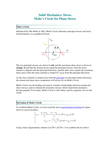
Mohr’s Circle of StressIn general we need to consider 3-D states of stress. The diagram belowshows three Mohr's circles for stresses acting on three sets of planes,each set containing one of the principal stress directions. In practice weoften limit consideration to planes containing the σ2 direction and plot onlythe biggest Mohr circle through σ1 and σ3.τσ3σ2σσ1By convention σ1 σ2 σ3Mohr’s Circle of Stress.David Nash4
Pole ConstructionThis is a simple graphical technique which can be used to find the state of stresson one plane of an element once you have constructed the Mohr's circle.Steps involved : Draw the element and Mohr's circle on the same sheet (see below)Identify a plane (say AC) on which you know the stresses and mark on Mohr'scircle (here point X at 1)Draw a line (ac) through X parallel to plane (AC) - where it cuts the circle that ispole PDraw a line (ab) through P parallel to plane (AB) on which you wish to knowstate of stress - where it cuts the circle that is stress state required (Y).BσyτYσ2τyAσ2Pθabθσ1acXσCσ1Mohr’s Circle of Stress.David Nash5
Geometry of CircleB1B2ααB3α2αACMohr’s Circle of Stress.David Nash6
Although location of pole P varies with relative orientation the point Y does not. Thetechnique can obviously be used to find the orientation of planes on which the state ofstress is known.YZXPMohr’s Circle of Stress.David Nash7
Note:Although in the examples given here the orientation of theelements is vertical/horizontal the pole method works verywell for any orientation of the soil element.In principle the calculation method may also be used for anyorientation but in practice most students find such problemsvery hard.Mohr’s Circle of Stress.David Nash8
Mohr’s Circle Example 1400100αWhat are stresses on planesinclined at α 45 and 60 ?Mohr’s Circle of Stress.David Nash9
Mohr’s Circle Example 1400What are stresses on planes inclined at α 45 and 60 ?ττ 130 σ 175Hτ 150 σ 250H100αP45 σ2 1002x45 σHσ1 400similarly for the 60 planeMohr’s Circle of Stress.David Nash10
Mohr’s Circle Example 2For the soil element shown, find:i)the magnitude of the principal stresses and theorientation of the major principal plane, andii) the stresses acting on the plane BB inclined at 20 .30050B50(-ve)10010050(-ve)B50300Mohr’s Circle of Stress.David Nash11
Mohr’s Circle Example 2What are magnitudes of σ1 and σ2, the orientation of plane 1-1,and the stresses on plane BB inclined at α 20 to the horizontal?First draw the Mohr’s circle through points H and V and find σ1 and σ2Next find the pole P by drawing from H or V.Next find the orientation of 1-1 plane by drawing from pole P.Next find the stresses on plane B-B.30050(-ve)B τ 104 σ 248σ150Bτ 50 σ 100PHτ 50 σ 30020 13 110010050(-ve)B150σ1σ2 88σ1 312100200300Vτ -50 σ 100300Mean stress (300 100)/2 200 kPaPlane BB is inclined at 20 to the horizontalRadius ((300-200)2 502) 111.8 kPaMohr’s Circle of Stress.David Nash12
Mohr’s Circle Example 3Worked solution to be given out after students attempt the problemMohr’s circle analysis step by stepa) using pole constructionb) by calculationA plane strain finite element analysis (2D-FEA) is made in order to predict the stress conditions atvarious critical locations of a proposed excavation. The results show the stresses at the end ofconstruction.You are required to draw the Mohr’s circle for an element at a critical location and to determine thestresses and orientations on critical planes.Mohr’s Circle of Stress.David Nash13
Finite element analysis of a road cuttingcutting to be excavated01623Y5X4Mohr’s Circle of Stress.David Nash14
Finite element meshMohr’s Circle of Stress.David Nash15
Example outputMohr’s Circle of Stress.David Nash16
Example outputMohr’s Circle of Stress.David Nash17
Incipient failure ?Examine stresses hereResults of 2D-FEA available (next slide)Mohr’s Circle of Stress.David Nash18
A plane strain finite element analysis is made in order to predict the stress conditions atvarious critical locations of a proposed excavation. The results show that the total normaland shear stresses (in kPa) at one such critical location, at the end of construction, will beas shown below. The pore pressure is 60 kPa.Carefully draw the Mohr's circle of effective stress to scale on graph paper for the soil atthis location, and determine (graphically or otherwise) :(i)the magnitudes of the effective principal stresses and orientations(relative to the horizontal) of the principal planes;(ii)the maximum stress ratio τ/σ' in this element of soil, and theorientations of the planes on which it is a maximum.902525170170u 60252590Mohr’s Circle of Stress.David Nash19
Mohr's Circle of Stress. David Nash Pole Construction Draw the element and Mohr's circle on the same sheet (see below) Identify a plane (say AC) on which you know the stresses and mark on Mohr's circle (here point X at 1) Draw a line (ac) through X parallel to plane (AC) - where it cuts the circle that is pole P
