![[Injection Moulding Calculations]](/img/6/124472923.jpg)
Transcription
[Injection Moulding Calculations]Table of ContentsDryer Residence Time Calculator . 2Barrel Residence Time Calculator . 3Hydraulic Speed Calculator . 4Projected Area Calculator . 6Clamp Tonnage and Cavity Pressure Calculator. 9Injection Speed and Fill Rate. 11Utilization Calculator . 12Thermal Expansion Calculator. 13THERMAL EXPANSION COEFFICIENTS . 16Cavity Dimension Calculator . 17It’s SADANANDA’sPage 1
[Injection Moulding Calculations]Dryer Residence Time CalculatorMany resins require drying prior to molding to remove either surface moistureor absorbed moisture from the pellets. In order to calculate residence time inthe dryer we must calculate the dryer weight capacity. A given dryer has aninternal volume, but will hold different weights of resin depending on thatresin's bulk density.First we must gather the knowns so as to calculate the unknowns:Knowns:Dryer hopper is 5.7 cu feet of capacity.We can weigh a sample or consult the resin supplier to determine the resin'sbulk density; in this example it will be 40 lbs/ft 3 .The molding cycle is 28.5 seconds and the shot size is 188.4 gr.We must first determine the molding press thruput rate or total pounds perhour processed.We convert 5.7 ft 3 dryer capacity topounds:We can now divide 228 lbs by 52.47 lbs/hrto get dryer residence time in hours:It is useful to reexamine the above calculation to review how we cancel units.Sometimes it is easy to forget the units, but this can result in incorrectconversions and incorrect answers if we do not perform all necessary steps tomake units come out right. If the units are wrong we will have a numericalanswer that is wrong for the intended calculation.It’s SADANANDA’sPage 2
[Injection Moulding Calculations]Barrel Residence Time CalculatorThe barrel residence time may be critical so as to avoid thermal degradation ofthe molding resin. Residence times can be too short and too long, but too longis the more common problem. In our example below we have a hot runnermold; thus, the hot runner system volume (internally heated passage ways) inthe mold is an extension of the barrel with regards to residence time atprocessing temperatures.First we must gather the knowns so as to calculate the unknowns:Knowns:Barrel rated capacity is 16.5 oz of GP styrene (1.06 gr/cc). Our resin ispolycarbonate with cold density or sp gr of 1.20 gr/cc. Molding cycle time is28.5 seconds and shot weight is 188.4 grams. Hot runner supplier tells us themelt channel's volume is 88 cm 3 .We convert the 88 cm 3 to styrenegrams as shown:We convert the 16.5 oz to grams asshown:The sum of these two calculations equals 561.1 grams (GP styrene); this is thevalue we will use for the barrel capacity (plus HR manifold).We perform the following calculation (note: sp gr is specific gravity):It’s SADANANDA’sPage 3
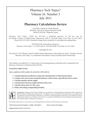
[Injection Moulding Calculations]We are using the rules for proportions tocalculate the barrel shot capacity (barrel only)with resin of different density - differentspecific gravity.Note: A 16.5 oz barrel of styrene holds 18.68oz of polycarbonate (18.68 oz 529.58grams):Hydraulic Speed CalculatorCalculation of cylinder extend & retract time (unscrewing core coupled withrack & pinion system in mold). This is a common scenario to accomplish theunscrewing action on cores for a closure mold. If the bore size is 2 inches; rodsize 1 inch and the stroke is 20 inches and our available core circuit oil volumeis 12 gal/min:It’s SADANANDA’sPage 4
[Injection Moulding Calculations]We divide the distance by the speed to get the time required. Hints todetermine what should be on top vs bottom of fraction:1. These units will cancel to get seconds on top as they should be.2. If we think about the numbers and realize that we are going 20 inches andwe can only go 14.7 inches per second - it must take longer than 1 sec to getthere!It’s SADANANDA’sPage 5
[Injection Moulding Calculations]Projected Area CalculatorOnly face shown at bottom of page is considered projected area for purposes ofcalculating clamp tonnage (area in X-Y plane or axis).Formed by a mechanical slide (shown on earlier pages). This technically does addsmall amount to equivalent projected area.It’s SADANANDA’sPage 6
[Injection Moulding Calculations]It’s SADANANDA’sPage 7
[Injection Moulding Calculations]It’s SADANANDA’sPage 8
[Injection Moulding Calculations]Clamp Tonnage and Cavity Pressure CalculatorThe principle of pressure amplification also acts on the mold cavities. If we arerunning the screw and injection unit at 750 psi hydraulic we would get 750 x14.52 or 10,890 psi leaving the nozzle and entering the mold. This force perIt’s SADANANDA’sPage 9
[Injection Moulding Calculations]area (pounds per square inch) acts on the projected area of the cavities to yieldsome amount of force in pounds trying to separate the mold halves. The clamptonnage works to keep the mold closed. The projected area is only the 2D areaof molded part surfaces in the X and Y directions only - do not count sidewallarea in the Z direction (part depth . . . in this example the Z axis/direction is inline with the screw).Note: This pressure amplification does ignore pressure drop which could be asmuch as 50%. The actual pressure varies at each location along the flow length- constantly being reduced by pressure drop in system. More sophisticatedmold filling analysis software is needed to accurately quantify the averagepressure in mold. If our equation shows ample tonnage working against fullcavity pressure, we know we are conservative which insures success.Not shown above is one additional system of pressure amplification in theclamp mechanism which generates the 300 tons of clamp force. As mentioned,300 tons is 600,000 pounds. If the typical system hydraulic pressure is 2000psi, we can calculate the clamp cylinder diameter to be 19.54 inches as shownat left. Note: This would apply to a hydraulic clamp system; toggle systems usea smaller cylinder plus other forms of mechanical advantage in the form oflever arms & linkages.It’s SADANANDA’sPage 10
[Injection Moulding Calculations]Injection Speed and Fill RateWe can calculate the injection speed using the formula below (machine pumpis given at 55 GPM):We calculate the volumetric injection rate (not injection speed) as follows:It’s SADANANDA’sPage 11
[Injection Moulding Calculations]If our part is polypropylene with a melt density of 0.70 gr/cm 3 (0.90 colddensity) and weighs 22.26 grams (same 4 cavity part described on previouspage); we can calculate the fastest possible fill time:Utilization CalculatorOverall utilization comes from calculating the following efficiencies; thenmultiply all components together for net affect:cycle eff std cycle actual cyclecavity eff actual running cavitation full cavitationmachine eff actual run time machine scheduledscrap eff 1 minus the molding scrap rateIt is important to understand that the overall efficiency is a product of all fourof the above, for example:It’s SADANANDA’sPage 12
[Injection Moulding Calculations]There are some plants which like to use 90-95% as an efficiency or utilizationvalue for pricing and scheduling the molding departments capacity. This maybe too aggressive and can result in molding output deficiencies relative to planas well as financial losses. As shown above, it is very easy to fall short of 90%overall efficiency. To accomplish 90%, the following scenario is needed:The 89% used in our pricing model from previous pages came from thisutilization table:Another way to demonstrate these numbers is the following calculation:When viewed as the equation above, it can be seen just how good we must beto accomplish 88.53% utilization.Thermal Expansion CalculatorThe following formula is used to calculate thermal expansion:Where the symbols mean the following:It’s SADANANDA’sPage 13
[Injection Moulding Calculations]Example: The leader pins on a mold are 18.75 inches apart. The "A" half is heatedfrom 70 F room temperature to 185 F and to 165 F on the ejector half; if themoldbase is steel, use 6.6 x 10 -6 or 6.6 X 0.000001 as the coefficient of thermalexpansion or use table if specific steel is known.The expansion between leader pins centers is calculated as follows:The bushing holes in "A" half will expand even more at 0.01423 inches since they arein hotter plates (185 instead of 165 F). This 0.0025 inch differential in leader pin tobushing spacing is about the maximum that can be tolerated unless the bushingholes are worn.Note also that the shut height of this mold is 11.751 inches. This will grow to be11.759 inches (0.008 inches increase).It’s SADANANDA’sPage 14
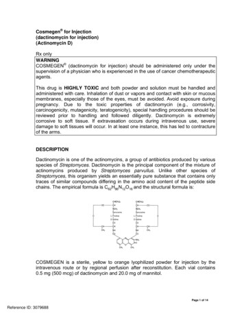
[Injection Moulding Calculations]This increase may be enough to throwoff the mold protection setup if setvery close; thus, requiring the clamplockup position to be readjusted aftertemperature equilibrium isestablished. Note that the mold islocated in press by the locating ringwhich is 3.99 inches for this mold.This is the center of the mold. Thermalexpansion will occur about this centerline. This is why the optimum locationfor taper locks (or straight locks) is atthe centers of the four sides (3, 6, 9 &12 o'clock positions). These locationslocations are unaffected by thermalexpansion about the mold's centerline.fig 1.It’s SADANANDA’sPage 15
[Injection Moulding Calculations]THERMAL EXPANSION COEFFICIENTSIt’s SADANANDA’sTYPE 200 F 400 F 800 F1020 6.5 6.7 7.14140 6.8 7.1 6150 6.8 7.1 7.4W1 5.8 6.1 7.3W2 7.4 8.0S1 6.9 7.5S5 6.4 7.0S6 6.4 7.0S7 6.8 7.0 7.4O1 5.8 5.9 7.1O2 6.2 7.0 7.7A2 5.8 5.9 7.2A6 6.4 6.9 7.5D2 5.6 5.7 6.6D3 6.3 6.5 7.2D4 6.2 6.9H10 6.1 6.8H11 6.2 6.9 7.1H13 5.8 6.4 6.8H14 6.1 H19 6.1 6.1 6.7H21 6.9 7.0 7.2H22 6.1 6.4T1 5.3 6.2T5 6.2 T15 5.5 6.1M1 5.9 6.3M2 5.2 6.2M3 6.45.6 7.0 5.4 Page 16
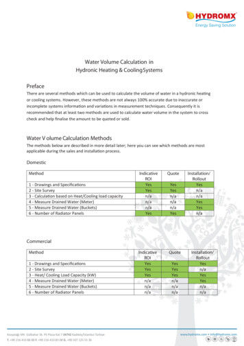
[Injection Moulding Calculations]M4 6.4M7 6.4M10 6.1L2 7.4 8.0L6 6.3 7.0P2 7.0 7.6P20 6.5 7.1SS 303,4 9.6 9.9 SS 316 8.8 9.0 SS 414 5.8 6.1 SS 420 5.7 6.0 SS 440 5.7 Ti alphaalloy Ti alphabeta 4.65.0Ti beta alloy 5.2Ampco 18, 21, 229.0Ampco 940 9.7FREE MACH Cu9.8BeCu (2%) 5.37.05.15.4 9.7 BeCu (0.5%) 9.8 6061 Aluminum13.1 INCONEL 6.4 4.85.25.6Cavity Dimension CalculatorThe tall round part below is made from polypropylene with a specified nominalshrink rate of 0.018 inches/inch (1.8%). This shrink rate is for shrinkage in theflow direction; the shrinkage in the transverse flow direction is only about 0.012inches per inch (transverse is 90 to flow direction). If we want to calculate thecavity dimension required to accomplish the 3.7500 part length, we would calculateas follows:It’s SADANANDA’sPage 17
[Injection Moulding Calculations]The previous line is a common incorrect method to size cavities.As you can see, if we use the wrong method of calculation, our answer can be off by0.0012 inches!If this part were made frompolyetherimide or other resin moldedat very hot mold temperatures wemight also need to calculate thethermal expansion. If mold temp was300 F, then steel thermal expansionwould add 0.0055 inches of partlength as follows:In this example the steel was H 13;thus, we used 6.4 x 10 -6 for thermalexpansion.We can calculate the cavity diameterat the 0.375 ID location in a similarmanner as length above, but weshould use a different shrink valuesince the shrinkage will be a functionof the transverse flow directionshrinkage. Our calculation wouldyield 0.3795 inches.fig 1.CALCULATING ACTUAL SHRINKAGEIt’s SADANANDA’sPage 18
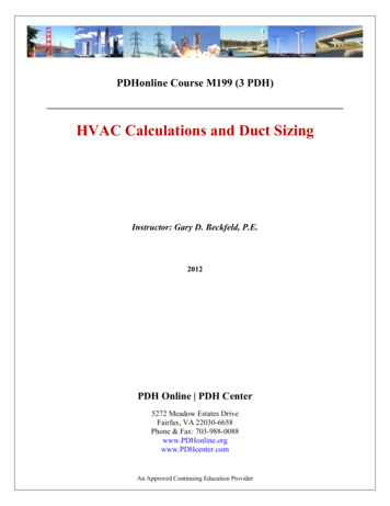
[Injection Moulding Calculations]cavity dimension:in.part dimension:in.shrinkage:in.Launch Unit ConverterView Conversion FactorsIf the part tolerances were very tight and critical; the preferred method ofestablishing the shrinkage would be to build a one to four cavity unit tool orprototype tool to accurately establish the actual shrink rates. This would beespecially important if multiple high cavitation molds were going to be built so as toavoid costly rework on later molds.Cavity dimensions determined from previous page are noted in parenthesis; we alsomust calculate cavity ID at bottom based on 0.25 degree angle used. Shrinkcalculations are as follows:It’s SADANANDA’sPage 19
[Injection Moulding Calculations]As can be seen there is more diametric shrink at end of fill than start of fill;this is due to pressure drop -- less packing means more shrink. Bothdiameters have less shrink rate than length shrink rate, since diametricshrink is a function of transverse flow direction shrinkage.Thank You Very Much, Sada It’s SADANANDA’sPage 20
Hydraulic Speed Calculator Calculation of cylinder extend & retract time (unscrewing core coupled with rack & pinion system in mold). This is a common scenario to accomplish the unscrewing action on cores for a closure mold. If the bore size is 2 inches; rod size 1 inch and the stroke is 20 inches and our available core circuit oil volume