Transcription
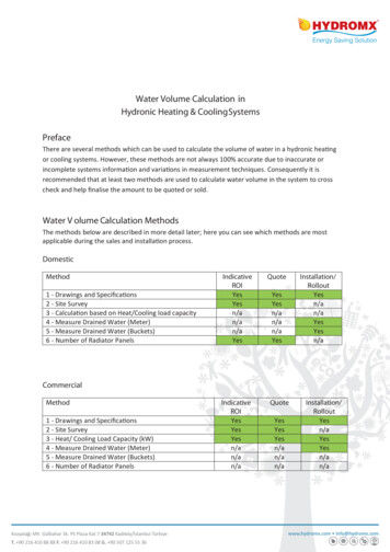
Water Volume Calculation inHydronic Heating & Cooling SystemsPrefaceThere are several methods which can be used to calculate the volume of water in a hydronic heatingor cooling systems. However, these methods are not always 100% accurate due to inaccurate orincomplete systems information and variations in measurement techniques. Consequently it isrecommended that at least two methods are used to calculate water volume in the system to crosscheck and help finalise the amount to be quoted or sold.Water V olume Calculation MethodsThe methods below are described in more detail later; here you can see which methods are mostapplicable during the sales and installation process.DomesticMethod1 - Drawings and Specifications2 - Site Survey3 - Calculation based on Heat/Cooling load capacity4 - Measure Drained Water (Meter)5 - Measure Drained Water (Buckets)6 - Number of Radiator mmercialMethod1 - Drawings and Specifications2 - Site Survey3 - Heat/ Cooling Load Capacity (kW)4 - Measure Drained Water (Meter)5 - Measure Drained Water (Buckets)6 - Number of Radiator PanelsKozyatağı Mh. Gülbahar Sk. PS Plaza Kat:7 34742 Kadıköy/İstanbul TürkiyeT. 90 216 410 88 88 F. 90 216 410 83 08 G. 90 507 125 55 dromx.com info@hydromx.com
As can be seen some methods are only applicable at the time of installation. These methods will addtime to the installation works, but will give the Installer a good indication that the correct amount ofwater has been drained, or indicate that there is more water in the system and it has not been fullydrained. When water has been left in the system it can be further drained or alternatively a higherconcentration of Hydromx can be installed to compensate and ensure the final solution is theoptimum 50% (see DR0005 Instructions for Use).1. Drawings and SpecificationsWater volume calculations can be made by taking sizing information from the building mechanicalproject materials lists and project drawings, (see Appendix A for pipe work volume calculation).Commercial buildings should have a mechanical project report and this report should include;Boiler/Chiller type and size, pipe type, length and diameters, main pump size and flow rates, fancoils, radiators, drainage points, air valves, pressure vessels etc. This information will enable acalculation of water volume in the system to be made.Also, many buildings have AutoCAD or similar computer drawings. In these cases, pipe work watervolume can be calculated with the help of these programs as well.Accuracy rate 90%.NOTE: Engineering variations may have altered the system and may not have been recorded onoriginal drawings or kept in up to date manuals. Where drawings are re-issued following variations,care should be taken to ensure information is taken from the latest issued drawings.2. Site SurveyWhere drawings are not available a walk through survey can be done to provide the information tocalculate volumes, (see Appendix A for pipe work volume calculation). Clearly this only applies forbuildings of a size than can be surveyed without excessive expense.The details of boilers, chillers, expansion vessel, pipe work and heat exchangers, etc. can becollected. Details of water volume sizing can be acquired from manuals, online specifications and byphone/email from manufacturers and distributors.Accuracy rate 90%.Kozyatağı Mh. Gülbahar Sk. PS Plaza Kat:7 34742 Kadıköy/İstanbul TürkiyeT. 90 216 410 88 88 F. 90 216 410 83 08 G. 90 507 125 55 36www.hydromx.com info@hydromx.com
3. Heat/Cooling load capacityThis method calculates water volume in heating and cooling systems based on heat load capacity.This is ONLY valid for Commercial installations, as Domestic boilers can be significantly oversized forthe property. With this method the thermal capacity (kW) of the boiler/chiller should be known.Heating systems formulakW x 0.014 m3m3 less %20 Estimated Water Volume in the systemBy applying the kW x 0.014 m3 formula the maximum water volume of the boiler is calculated;then subtract 20% (typical heat engineering boiler sizing tolerance margin) to give the estimatedwater volume in the system.In making this calculation it is very important to know the accurate kW heat capacity of the activeboilers. For example there may be a primary boiler is the main feeder and a secondary/backupboiler. The calculation must use the kW of the heating needed for the building, and exclude backupand capacity tolerances.NOTE: 20% is a typical boiler capacity tolerance margin, but this may vary. This exact boiler capacitytolerance may be available in the original Heat Engineering calculations.EXAMPLESExample1The system has one 1400 kW boiler.1400 kW x 0.014 19.6 m319.6 m3 - %20 15.68 m3 estimated water volume in thesystem.Example 2The system has two boilers which are working together, (both are 1400 kW). In this situation thetotal kW (the working load)of the boilers must be used in the formula(1400 kW 1400 kW) * 0.014 39.2 m 339.2 m3 - %20 31.36 m 3 estimated watervolume in the system.NOTE: If there is more than one boiler in the system and it is uncertain whether the other boilers areback ups or not, a different method should be used to calculate the water volume.Kozyatağı Mh. Gülbahar Sk. PS Plaza Kat:7 34742 Kadıköy/İstanbul TürkiyeT. 90 216 410 88 88 F. 90 216 410 83 08 G. 90 507 125 55 36www.hydromx.com info@hydromx.com
Chiller systems formulakW x 0.014 x 1.32 m 3m3 - %20 Water Volume in the systemTo use this formula it is essential to know which is the Primary chiller and which chiller is thesecondary/back up. The maximum working load of PRIMARY feeders ONLY should be calculated. Aswith the Heating Systems Formula this formula also includes a tolerance factor of 20%.EXAMPLESExample 1The system has one 488 kW chiller.488 kW x 0.014 x 1.32 9 m39m3 - %20 7.2 m 3 estimated water volume in the system.NOTE: If there is more than one chiller the maximum working load should be calculated as belowand one other method should be used for verification.Example 2The system has three chillers of 500 kW, 300 kW and 300 kW respectively, which are workingtogether as a main feeder.(500 kW 300 kW 300 kW) x 0.014 x 1.32 20.328 m320.3 m3 - %20 16.24 m3estimated water volume in the systemIf the kW of the Boiler/ Chiller is unknownIf the main pump/pumps flow rate and the ΔT of the chiller/boiler (for example, chillers usually have3 C ΔT (input 10 C, output 7 C) are known the estimated kW of the system can be calculated usingthe formula:kW (m/h) * T/0.86Secondary pumps are only for back up and should not be included in the calculation if they are notworking together as main pumps.Kozyatağı Mh. Gülbahar Sk. PS Plaza Kat:7 34742 Kadıköy/İstanbul TürkiyeT. 90 216 410 88 88 F. 90 216 410 83 08 G. 90 507 125 55 36www.hydromx.com info@hydromx.com
EXAMPLEThe main pump of the system has 120 lt/h flow rate and if there is 3 C ΔT.120 lt/h x 3 C / 0.86 418 KWWater volume calculation based on heat load capacity generally gives the minimum amount ofwater. The accuracy of this method depends on the accuracy and completeness of the informationprovided by customer’s technical team. It is strongly recommended that another method is alsoused to calculate the volume of water in the system.Accuracy rate 80 - 90%. depending on the accuracy of the engineering calculations on the originalconstruction drawings and the accurate tracking of any engineering variations.4. Measure drained water (meter)Providing there is a single connection point through which the whole system can be drained this isthe easiest way to measure water volume in the system.Whilst draining the system the water temperature should be the same as normal tap water. If thewater is hotter it will be less dense and this may affect the accuracy of the measurement.Kozyatağı Mh. Gülbahar Sk. PS Plaza Kat:7 34742 Kadıköy/İstanbul TürkiyeT. 90 216 410 88 88 F. 90 216 410 83 08 G. 90 507 125 55 36www.hydromx.com info@hydromx.com
In larger systems this method can increase draining time and therefore several draining points maybe required with a meter connected at each point.Care should be taken to avoid the formation of bubbles while draining the system as this may giveinaccurate results as the water meter will count bubbles as water.Accuracy rate for smaller systems 90%.Accuracy rate for large systems 70-80% as this assumes that the residual water left in larger systemsis a greater proportion than smaller ones.5. Measure drained water (bucket)This method is the preferable method for small domestic type properties where drained water canbe collected in a measuring bucket and the total water volume is summed from the number ofbuckets and measured amounts.Accuracy rate 90% assumes 10% residual water is left in system.6. Number of radiator panels x average number of litres per panelThis method is suitable as a method for indicative quotes for domestic scale properties and can bevaried with experience of house types. Although this method does not always accurately allow foropen vented header tanks, over sized expansion vessels, or low water capacity radiators/emitters, itis a good initial assessment.EXAMPLEThis example assumes a typical 3/4 bedroom detached house would have installed 15mm copperpipes and steel radiators. For each radiator panel a figure of 7 litres per panel is used, which gives anaverage water volume for the entire system.Therefore in a house with 6 single panel radiators and 5 double radiators (10 panels) the estimatedvolume of water in the system is 112 litres.e.g. ( 6 single panels 10 panels in double radiators) x 7 litres 112 litresAccuracy rate for domestic type systems 85%.Kozyatağı Mh. Gülbahar Sk. PS Plaza Kat:7 34742 Kadıköy/İstanbul TürkiyeT. 90 216 410 88 88 F. 90 216 410 83 08 G. 90 507 125 55 36www.hydromx.com info@hydromx.com
Appendix A - Pipe Volume CalculationsThe following formulas and worked example show how to calculate the volume of pipe work, oncean assessment of the length of pipe work and sizes has been made from a walk through survey orfrom drawings.Pipe capacity calculation formulaV π x R1 x R1 x L x 1000Where:V volume in Litresπ 3.14159R1 internal radius of pipe in metersL length in meters1000 number of litres in 1m3 DN diameter nominalEXAMPLESExample 1Calculation of 10 meters of 1" (DN 25) pipe.Using the figures in Table 1 R1 is calculated as:R1 Inner diameter/1000/226.9/1000/2 0.014V π x R1 x R1 x L x 10003.14 x 0.014 x 0.014 x 10 x 1000 6.15 litresKozyatağı Mh. Gülbahar Sk. PS Plaza Kat:7 34742 Kadıköy/İstanbul TürkiyeT. 90 216 410 88 88 F. 90 216 410 83 08 G. 90 507 125 55 36www.hydromx.com info@hydromx.com
Example 2Calculation of 3 meters of 1/2” (DN 15) pipe.Using the figures in Table 1 R1 is calculated as:R1 Inner diameter/1000/215.7/1000/2 0.008V π x R1 x R1 x L x 10003.14 x 0.008 x 0.008 x 3 x 1000 0.6 litresTable of nominal diameter and pipe PE THICKNESS (mm)INNERDIAMETER(mm)1/2ʺDN 1521.32.815.73/4ʺDN 2026.92.921.11ʺDN 2533.73.426.911/4ʺDN 3242.43.635.211/2ʺDN 4048.33.740.9DN 5060.33.952.5DN 6573.05.2062.63ʺDN 8088.95.577.94ʺDN 100114.36102.35ʺDN 125141.06.6127.86ʺDN 150168.37.1154.18ʺDN 200219.18.18202.7412ʺDN 3003239.5304.016ʺDN 4004069.5387.018ʺDN 4504709.5451.02ʺ21/2ʺTable 1Kozyatağı Mh. Gülbahar Sk. PS Plaza Kat:7 34742 Kadıköy/İstanbul TürkiyeT. 90 216 410 88 88 F. 90 216 410 83 08 G. 90 507 125 55 36www.hydromx.com info@hydromx.com
Chiller systems formula kW x 0.014 x 31.32 m3 m - %20 Water Volume in the system To use this formula it is essentia lto know which is the Primary chiller and