Transcription
ADVANCEDOperating and Installation ManualOPERATIONANGLE of ATTACKAOA Sport and ProPart #REPAIRS & rCALIBRATIONUS Patent 6,271,769 B1Serial #:Advanced Flight Systems, Inc.www.Angle-of-Attack.comAOA MANUAL REV417605COPYRIGHT 2000-2004Jan. 1, 2004 i
Intentionally Blankii Jan. 1, 2004
Warranty and Registration CardLIMITED WARRANTY AGREEMENTAdvanced Flight Systems, Inc. warrants its AOA instrument andsystem components to be free from defects in materials andworkmanship for a period of one year commencing on the dateof the first flight of the instrument. Advanced Flight Systems,Inc. (AFS) will repair or replace the instrument or systemcomponents under the terms of this Warranty provided the itemis returned to AFS prepaid.1. This Warranty shall not apply to any unit or component thathas been repaired or altered by any person other than AFS,or that has been subjected to misuse, abuse, accident,incorrect wiring, or improper or unprofessional installationby any person. THIS WARRANTY DOES NOT COVERANY REIMBURSEMENT FOR ANYONE'S TIME FORINSTALLATION, REMOVAL, ASSEMBLY OR REPAIR.AFS reserves the right to determine the reason or cause forwarranty repair.2. This Warranty does not extend to any aircraft, or any otherdevice to which the AFS AOA system may be connected,attached, or used with in any way.3. THE REMEDIES AVAILABLE TO THE PURCHASERARE LIMITED TO REPAIR, REPLACEMENT, ORREFUND OF THE PURCHASE PRICE OF THEPRODUCT, AT THE SOLE DISCRETION OF AFS.CONSEQUENTIAL DAMAGES, SUCH AS DAMAGE TOTHE AIRCRAFT, ARE NOT COVERED, AND AREEXCLUDED. DAMAGES FOR PHYSICAL INJURY TOPERSON OR PROPERTY ARE NOT COVERED, ANDARE EXCLUDED.Jan. 1, 2004 iii
4. AFS is not liable for expenses incurred by the customer orinstaller due to AFS updates, modifications, improvements,upgrades, changes, notices or alterations to the product.5. The pilot must understand the operation of this productbefore flying the aircraft. Do not allow anyone to operatethe aircraft that does not understand the operation of theAOA system. Keep the operating manual in the aircraft atall times.6. No one is authorized to assume any other or additionalliability for AFS in connection with the sale of AFSproducts.7. IF YOU DO NOT AGREE TO ACCEPT THE TERMS OFTHIS WARRANTY, YOU MAY RETURN THEPRODUCT FOR A FULL REFUND. IF YOU DO NOTAGREE TO ACCEPT THE TERMS OF THISWARRANTY, DO NOT INSTALL THE PRODUCT.8. This warranty is made only to the original purchaser and isnot transferable. THIS WARRANTY IS IN LIEU OF ALLOTHER WARRANTIES OR OBLIGATIONS, EXPRESSOR IMPLIED, ORAL OR WRITTEN. AFS EXPRESSLYDISCLAIMS ALL IMPLIED WARRANTIES OFMERCHANTABILITY OR FITNESS FOR APARTICULAR PURPOSE. THE PURCHASER AGREESTHAT IN NO EVENT SHALL AFS BE LIABLE FORSPECIAL, INCIDENTAL OR CONSEQUENTIALDAMAGES, INCLUDING DAMAGES TO THE ENGINEOR AIRCRAFT, LOST PROFITS, LOSS OF USE, OROTHER ECONOMIC LOSS. EXCEPT AS EXPRESSLYPROVIDED HEREIN, AFS DISCLAIMS ALL OTHERLIABILITY TO THE PURCHASER OR ANY OTHERPERSON IN CONNECTION WITH THE USE ORPERFORMANCE OF AFS's PRODUCTS, INCLUDINGBUT NOT LIMITED TO STRICT PRODUCTSLIABILITY IN TORT.iv Jan. 1, 2004
Registration CardTo receive important notification of Service Bulletins,AOA Manual updates and service difficulty reports,please fill out the following and mail to:Advanced Flight Systems Inc.16285 SW 85th Ave, Suite #401Tigard OR 97224 USAOwner's Name:Address:City:State: Postal Code ZIP:Country:Home telephone:Business Telephone:E-mail:Aircraft Model and N#:P/N of CPU: Serial Number of CPU:Installer:Jan. 1, 2004 v
Intentionally Blankvi Jan. 1, 2004
Table of ContentsI. OPERATOR AND INSTALLER REQUIREMENTS 1FREE TECHNICAL CONSULTATION6II. HOW IT WORKS 7THEORY OF OPERATIONAOA DISPLAYSMODES OF OPERATIONAIRCRAFT DATA BASE CONFIGURATIONS7101113III. WHAT TO DO FIRST 20INVENTORY OF PARTS20IV. CAUTIONS 22V. PANEL OR GLARE SHIELD INSTALLATIONS 24PANEL MOUNTSSPORT GLARE SHIELD MOUNTSPRO GLARE SHIELD TRIM KIT242526VI. AOA CPU TRAY INSTALLATION 28VII. WING PRESSURE PORTS INSTALLATION 30VIII. PITOT STATIC TEE INSTALLATION 36IX. FLAP AND GEAR SWITCH INSTALLATION 38X. WIRING INSTALLATION 40XI. POST INSTALLATION TEST 46XII. CALIBRATING PROCEDURES 48XIII. SPORT CALIBRATION 50XIV. PRO CALIBRATION 58Jan. 1, 2004 vii
XV. ADVANCED APPLICATIONS 66GEAR WARNINGADJUSTING PRESSURE AMPLIFIER GAINSPORT GAIN ADJUSTMENTSPRO GAIN ADJUSTMENTSSLUING ANGLE ADVISORY AND PERFORMANCE DATAOPEN COLLECTOR WIRING OPTIONSBACKUP POWER WIRING OPTIONS66676869707272XVI. WARRANTY REPAIRS AND CLEANING 74MAINTENANCE SERVICECLEANING THE SPORT DISPLAYCLEANING THE PRO DISPLAY747475APPENDIX 78A. AOA REVIEW 78B. ELECTRICAL CONNECTIONS 94SPORT PIN OUTPRO PIN OUTPICTORIAL SCHEMATIC SPORTPICTORIAL SCHEMATIC PRO94959697C. PANEL CUTOUT 98PANEL CUTOUT SPORTPANEL CUTOUT PRO9899D. SPECIFICATIONS 100E. ERROR MESSAGES 102F. CHECKLISTS 104G. INVENTORY 106viii Jan. 1, 2004
H. TROUBLE SHOOTING 108I. PORT LOCATIONS/FLAP SWITCH CLOSURES 110J. REVISIONS 114Jan. 1, 2004 ix
Intentionally Blankx Jan. 1, 2004
OPERATOR AND INSTALLER REQUIREMENTSI. Operator and Installer RequirementsOPERATIONThe AOA Instrument will never be used as a primaryinstrument and must be placarded as such. Installation ofthe AOA on experimental aircraft is considered a minoralteration and as such does not require anything other thana logbook entry. Installation on production or certifiedaircraft requires FAA approval (Form 337) which may bedifficult or impossible to receive. This experimentalinstrument is not FAA certified or approved. Improperinstallation or usage on aircraft may cause death or injury.Prior to flying AOA instrumentation, the pilot must obtainflight instruction from a qualified instructor. Anemphasis item in AOA training is that wingscontaminated with insects, dust, frost or ice stall at higherairspeeds and reach their critical AOA at lower angles.This is especially true of highly laminar airfoils that aregenerally more sensitive to light contaminants andenvironmental conditions than non-critical and turbulentboundary flow airfoils. Another emphasis item is thattractor powered aircraft will reach critical AOAs poweroff at a lower AOA and higher IAS than power on due topropeller effects.Calibration of the instrument is critical for properoperation. A zero "g" and a descending power on slowflight maneuver must be flown in smooth air during theone time calibration process in both the cruise and landingflaps configuration. In addition, the pilots performing thecalibration must determine for those in-between flapsettings whether the cruise flaps or the landing flapsdatabase should be used to compute AOA. This requiresmaking the proper flap switch adjustments to insure theJan. 1, 2004 1
OPERATOR AND INSTALLER REQUIREMENTShigh angle warning provides the desired margin prior toreaching the critical AOA. Guidance for aircraft flapswitch setup, port locations and other frequently askedquestions may be obtained by referring to Appendix I orvia the internet at www.angle-of-attack.com frequentlyasked questions.Some AOAs may be shipped with aircraft calibration datapre-installed. If you choose to use this data, you mustverify the validity of the data or calibrate the AOA tomeet your specifications. Checklists are included oravailable from our web site.You assume all liability for the appropriate application,construction, calibration, maintenance and installation.Application, construction, calibration or installation errorsmay cause death or injury. Please read the instructions!For example, details such as the void above the lowerpressure tap are important for proper operation. Do notfill the void with sealant or epoxies.The instructions that follow, are of an advisory nature,may not apply to the particular installation, and maycontain errors. Advanced Flight Systems Inc. makes nowarranty, other than that in the Warranty Agreement, withregard to this material, including, but not limited to, theimplied warranties of merchantability and fitness for aparticular purpose. Advanced Flight Systems Inc. shallnot be liable for errors contained herein or for incidentalor consequential damages in connection with thefurnishing, performance, or use of this material.This document contains proprietary information that isprotected by copyright , patent and a patent pending.2 Jan. 1, 2004
OPERATOR AND INSTALLER REQUIREMENTSOPERATIONAll rights are reserved. No part of this document may bereproduced, or translated to another language withoutwritten consent of Advanced Flight Systems Inc. Theinformation contained herein is subject to change withoutnotice.All operators using this AOA must read the manual in itsentirety. Each installation is different and the installerand owner are solely responsible to insure that the usageis appropriate and safe.You must include in your preflight checklist:Wing Pressure Ports. CHECKEDPitot/Static Ports. CHECKEDAir/Water Separator . DRAINEDYou must add to your Aircraft Operating Handbook thepilot operating instructions for verifying that the AOAsystem is working properly. You must include in yourbefore take off checklist the Angle-of-Attack Push to Testcheck that is detailed within the Pilot OperatingHandbook and faithfully execute the check prior to eachflight:Angle of Attack . TEST/CHECKEDAt each annual condition inspection, the results of theAOA Instrument inspection, verification and test must berecorded on an annual condition inspection checklist.When using the AOA Instrument, cross checking to theairspeed indicator for reasonableness checks are requiredJan. 1, 2004 3
OPERATOR AND INSTALLER REQUIREMENTSand your airspeed indicator always takes priority in theevent of disputes. The AOA Display must be placardwith “NOT TO BE USED AS A PRIMARYINSTRUMENT.”An up to date AOA Operator’s and, Installation Manualmust be available to the pilot at all times. The entiremanual is downloadable free from our web site atwww.angle-of-attack.com and also available in print for asmall fee upon request. Please keep your AOA manualup to date with new inserts as required.The pressure ports must be placarded withand the area around the ports must never be powerwashed. Care must be taken not to plug the ports withwax or polishing compounds.The AOA drain must be placarded with:Any errors during tests, inspections or checks shall benoted in the aircraft log book, the pitot/static tubes cappedto prevent pitot/static errors and the instrumentdisconnected and placarded as inoperative in accordancewith MEL's and FAR's.4 Jan. 1, 2004
OPERATOR AND INSTALLER REQUIREMENTSOPERATIONThe AOA Instrument or its parts are not to be resoldwithout prior approval of Advanced Flight Systems Inc.Stall warning devices and AOA devices are different indesign. This AOA instrument does not meet the FAATSO requirements for stall warning devices.A failure of the Pitot/Static pneumatic system such astaking off with a covered pitot tube will cause the AOA togive false and unreliable information.This system, like other electrical systems, requires aminimum voltage, fuse protection and an air-conditionedenvironment to function properly. The electrical andtemperature specifications are listed in Appendix D. Aseparate circuit breaker that can be pulled to disable theAOA in flight is mandatory and must be in reach of thepilot in command.Should any of the above be impractical or impossible toimplement, the AOA Instrument must be returned in anew condition for a refund within 60 days.Jan. 1, 2004 5
OPERATOR AND INSTALLER REQUIREMENTSFree Technical ConsultationIf you need technical advise E-mail AFS@angle-ofattack.com. It is advisable to have this manual on handfor reference.Your AOA Instrument has a part number affixed to theAOA CPU and the same number should be entered on thefirst page of your owner's handbook and the warrantyregistration card. This number will be helpful todetermine how your instrument was configured. Thisnumber should also be available prior to calling.Please fill out the warranty registration card and keepyour address updated to insure you receive ServiceBulletins and Service Difficulty Reports. The latestService Bulletins and Service Difficulty Reports arealways available on our web site at www.angle-of-attack.com.6 Jan. 1, 2004
HOW IT WORKSII. How it WorksOPERATIONYou have acquired a powerful instrument that isexperimental by nature and will require initial calibrationand/or verification by you for your aircraft.Please review Appendix A and take the quiz coming backto this point in the manual when finished. If you are aNavy or Marine carrier pilot, the material in Appendix Amay look familiar. Review of Appendix A completedTheory of OperationThe AOA Instrument is based upon sound aerodynamicprinciple. The term "angle of attack” is the anglebetween the relative wind and the chord of the airfoil.The new term you may not be familiar with is "anglefrom zero lift” which is the angle measured from thereference angle when aligned with the relative windcreates no lift. Angle of attack and angle from zero liftare identical to each other for symmetrical airfoils. Fornon-symmetrical airfoils, the difference between angle ofattack and angle from zero lift is a fixed constant. Whenthe term angle of attack or AOA is used for nonsymmetrical airfoils, the term angle from zero lift shouldbe substituted in order to be technically correct. YourAOA Instrument technically measures angles from zerolift. When the PRO display indicates 0 units AOA, theaircraft properly calibrated is creating no lift.The Angle of Attack Instrument (AOA Instrument)utilizes pressures from two pressure ports located on youraircraft’s upper and lower airfoil or probe, and pressuresJan. 1, 2004 7
HOW IT WORKSfrom your aircraft’s pitot and static ports. The result ofdividing the airfoil or probe differential pressure Pw bythe pitot static differential pressure Pp is a coefficient ofpressure (CP). There is a unique variation of CP withangle of attack. This variation is very linear over most ofthe airfoil's AOA.The process of calibrating the full range AOA Instrumentto a specific airfoil requires as few as two coefficients ofpressure that are permanently recorded into the angle ofattack instrument’s memory. The CPs include a zero liftCP and an angle advisory CP. These two CPs are thenused to define the slope and intercept of the straight-linerelationship between the coefficient of pressure and theangle from zero lift. This is easily accomplished in oneshort flight. Once the system is calibrated with these twoCPs, all other coefficients of pressure can be equated to aspecific angle from zero lift.The coefficient of pressure at zero lift (0L) is determinedby performing an in flight 0 "g" maneuver. Thecoefficient of pressure at angle advisory (AA) is8 Jan. 1, 2004
HOW IT WORKSOPERATIONdetermined by flying at the AOA or airspeed at 1 "g"where it is desirable to have the high AOA warningsactivate (“angle angle push”) usually at 1.15 times thestalling speed.The upper and lower airfoil pressure ports may be simplysmall holes in the upper and lower surfaces of the wingconnected to tubes routed to the AOA CPU eliminatingthe requirement for a probe altogether or may be from analpha probe. The pressure ports for the pitot and staticpressures may be from the pitot/static tube or individualpitot and static ports. Pick the pitot/static pressures byteeing into the pitot static systems just behind the airspeedindicator.The angle of attack is displayed on an AOA instrument.When the AOA reaches high angles of attack, the AOAInstrument issues electrical, verbal and visual warnings.FAR 23.207 requires stall warnings to begin at a speedexceeding the stalling speed by a margin of not less than 5knots but not more than the greater of 10 knots or 15% ofthe stalling speed. Since the AOA Instrument is not anairspeed indicator, the term “stall warning” as defined bythe FAA and FAR’s does not apply to this AOAInstrument. We shall use the term "angle advisory”.During the calibration process, AOA is used to determinewhere the angle advisory will activate.The AOA Instrument will provide AOA information tothe aircraft pilot and warnings when the AOA is at highangles and when the airfoil is operating at the optimumAOA for an approach and operating at some otherperformance related AOA such as the maximumendurance or best glide angle. It should be noted that ice,Jan. 1, 2004 9
HOW IT WORKSfrost, dust and insects adhering to the wing will increasethe stalling speed and decrease the critical AOA.AOA DisplaysThe AOA Sport Instrument’s display is athree color light emitting diode (LED) eightladder display which shall be located on theinstrument panel or the glare shield.The AOA Pro Instrument’s display is a fourcolor liquid crystal display that shall belocated on the instrument panel or the glareshield.10 Jan. 1, 2004
HOW IT WORKSModes of OperationOPERATIONThere are three modes of operation:1. the Flight mode when the AOA Instrument isindicating AOA information and warnings and thedisplay is moving up and down as AOA is increasingand decreasing;2. the Test mode when the AOA Instrument is goingthrough its self test;3. and the Calibration mode as indicated on the Sportdisplay by pattern of flashing LEDs or on the Prowhen a 0 or 1 is followed by alpha characters.When in the calibration mode, there are five (5) pages tochoose from for the Sport and seven (7) for the Pro asfollows:1. The Hangar Calibration (HC) page is used to establishvoltage offsets for the wing and the pitot/staticdifferential pressure transducers at zero differentialpressure. Each pressure sensor is unique.2. The Zero "g" or Zero Lift page (0L) is used toestablish the coefficient of pressure at an AOA wherethe aircraft is creating no lift.3. The Angle Advisory page (AA) is used to establishthe coefficient of pressure at an AOA where highangle warnings should activate.4.(Pro Only) The Approach page (AP) is used toestablish the coefficient of pressure at an AOA wherethe aircraft is at an optimum approach AOA.Jan. 1, 2004 11
HOW IT WORKS5. (Pro Only) The Performance page (PF) is used toestablish the coefficient of pressure at an AOA wherethe aircraft is at some optimum performance AOAtypically the best L/D AOA or maximum enduranceAOA.6. (Pro Standard and Sport Optional) The landing gearwarning page (LE) is used to establish the minimumairspeed where, if the gear is not down, a “LandingGear” warning is enunciated.7. The Save page (SA) is used to write all the data savedabove in RAM to permanent memory (EEPROM).12 Jan. 1, 2004
HOW IT WORKSAircraft Data Base ConfigurationsOPERATIONThe AOA Instrument senses when the aircraft is in one oftwo configurations using a simple micro switch connectedto the flap movement mechanism:1. The cruise or clean configuration when the flaps areup.2. The landing configuration when the flaps are not inthe up position or in the down position for landingsetting.For in-between flap configuration settings, the flap switchis configured so that the AOA CPU uses the mostconservative database for computing AOA.Jan. 1, 2004 13
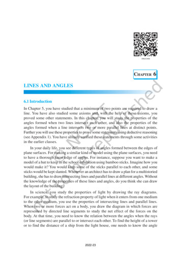
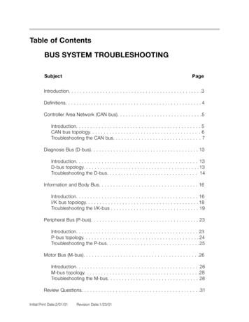
HOW IT WORKSAOA Sport and Pro CPU(Computer or Brain Box))The angle of attack central processing unit is enclosed in analuminum tray. Although both the Sport and Pro are housed inidentically shaped trays, there are major differences in theelectronics. The 25 pin Dsub is for wiring the CPU to the display,the power supply, the push to test (PTT), dimmer and flap positionswitch. The four barbs will be connected to 1/8” OD color-codedpressure tubing.The PCB (printed circuit board) is populated with a microprocessor,an EEPROM memory chip, a chip used for the audio play back ofwarning and error messages and a fuse. There is no battery in theCPU since the EEPROM memory chip does not require a battery toremember data.14 Jan. 1, 2004
OPERATIONHOW IT WORKSJan. 1, 2004 15
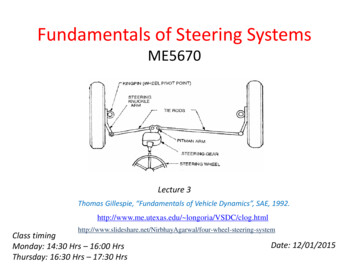
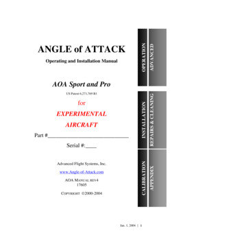
HOW IT WORKSAOA Sport LED DisplayThe display is a custom three color LED ladder. Eight LEDsegments are individually controlled by the microprocessor. Amomentary push button switch controls the brightness. These bulbshave a typical life of about 100,000 hours. The display is alsoavailable in a glare shield mount.The two bottom LEDs are green, the three above are yellow and thetop three LEDs are red.The bezel is black Delrin and was precision milled.16 Jan. 1, 2004
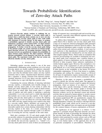
OPERATIONHOW IT WORKSAOA Pro LCD DisplayThe angle of attack liquid crystal display is a custom four colordisplay and back lit with 100,000 hour white LEDs. The power forthe back light comes from the AOA CPU PCB. Fifty-two light barsegments are individually controlled by the microprocessor (directdrive) providing the maximum contrast possible. Due to polarizing,the display reads best when viewed straight on and from above.The back of the LCD includes the surface mounted electronics.Inside the display is a light board to further increase the contrast.The bezel is black anodized and was precision milled from solidaluminum.Jan. 1, 2004 17
HOW IT WORKSSwitches and Push ButtonsFor aircraft equipped with flaps, slats, and/or retractable gear,microswitches sense whether the aircraft is in the landing or thecruise configuration.A red push to test (PTT) button and a black instrument dimmerbutton is supplied. When both buttons are pushed and released at thesame time, you enter the calibration mode.18 Jan. 1, 2004
OPERATIONHOW IT WORKSIntentionally BlankJan. 1, 2004 19
WHAT TO DO FIRSTIII. What to Do FirstTake a look at the layout of this manual by quicklythumbing through each page. Note that the appendixcontains lots of valuable information.It is recommended that the steps be completed in order. Asmall box has been inserted in front of each orderedinstruction for you to check as you complete eachinstruction.Inventory of PartsNow is a good time to inventory the shipment. Refer toAppendix G for the list of materials shipped.20 Jan. 1, 2004
WHAT TO DO FIRST Inventory complete (either "A" or "B" or "AB" kit) The wiring harness was inspected but not electricallytested prior to shipment. Referring to appendix B,ring out the wiring harness now! This will confirmthat the connections are good and correct and maysave you lots of grief later should there be a problem. For some aircraft like the RV4, 6, 7, 8, and 10 theports must be located in the wing at the properlocation. For the Lancair Legacy the wing parts arepreinstalled. In the above cases, the port location iscritical and the CPU was shipped pre calibrated. Seeappendix I for the exact port locations. Withproperly located ports and a pre calibrated CPU, youneed only verify that the AOA indications are correct(see the "Verification" yellow checklist).Jan. 1, 2004 OPERATIONThe AOA CPU (angle of attack central processing unit)was thoroughly electrically checked for proper operationusing a test box. The AOA LED or LCD display was alsotested prior to shipment. If you encounter any qualitycontrol problems, please return the part for repair orreplacement.21
CAUTIONSIV. Cautions Calibration of the AOA Instrument requires a zero Gmaneuver in the cruise and landing configuration.Remove any loose items from the aircraft cabin orbaggage compartment and check the enginecompartment and remove any loose bolts etc. that arenot properly secured and may move during thismaneuver. Calibration of the AOA Instrument requires adescending slow flight maneuver in the cruise andlanding configuration. On humid days and at lowpower settings carburetors and even throttle bodieswill ice up causing engine stoppage. Use carburetorheat and clear the engine frequently as required inyour pilots' aircraft operating manual. The AOA Instrument flap, gear, PTT, and dimmerDsub pins and switches shall not have a power supplyconnected to them. Simply switching these pins to aground will provide the signal that is required.Voltages applied to these pins may damage the AOACPU. The accuracy, fidelity and reliability of the AOAInstrument are dependent upon several factors. Thelocation of the pressure ports relative to the wing,accuracy of the pitot static system, and the quality ofthe job done in calibrating the AOA Instrument are ofmost significance. The AOA Instrument shall never be used as a primaryinstrument during any flight maneuver. It may be22 Jan. 1, 2004
CAUTIONS The critical AOA verbal warning will occur at a lowerAOA and higher airspeeds when the airfoil iscontaminated. Power off flight in tractor drivenaircraft may result in a lower critical AOA and ahigher stalling IAS than with power on due topropeller effects. If the AOA CPU is removed for repair or service,prior to flight cap the red and clear tubes to insure thatthe pitot/static system continues to work properly. The AOA requires pitot/static system inputs tooperate. The installation of a separate pitot/staticsystem would provide more redundancy and isrecommended. The gear warning system does not arm and cannotissue warnings until the IAS exceeds the landing gearwarning speed (usually after takeoff). Setting thelanding gear warning speed too high could result inthe system never arming during a slow flight aroundthe pattern. Setting the landing gear warning speedtoo low could eliminate warnings altogether. OPERATIONused as a backup to primary instruments such as theairspeed indicator.The pressure tubes must not be crimped. Theminimum bend radius is 3/4". Be careful whenremoving and reinstalling adjacent equipment thatcould crimp the tubes.Jan. 1, 2004 23
PANEL OR GLARE SHIELD INSTALLATIONSV. Panel or Glare Shield Installations A. See Appendix C. The AOA display will normallybe mounted on the instrument panel or on the glareshield. Note that there are two styles of Sportinstrument bezels panel and glare shield. A trim kitis available for the Pro if it is mounted other thanon a panel. A metal template is available for allpanel mounted displays to insure clean andaccurate panel cutouts. B. The AOA Sport display bezel is milled from Delrinand care is required to prevent stripping thethreads. The proper method to torque the mountingscrews is to bottom them out then rotate one-eighthadditional turn.Panel mounts C. Locate the template on the front of the instrumentpanel and positioning it straight up and down.Securely attach the template to the panel usingpackers tape or drill a small hole through the centerof the bezel and bolt into place on the instrumentpanel.Using a 1/8" drill bit and the top and bottomtemplate guide holes, spot face the panel justenough to leave centering marks. Remove thetemplate. D. Using a 1/16 drill bit and using the centeringmarks, drill through the panel. Using a #32 drill bit(1/8" bit is OK), open up the holes to accept a 4-4024 Jan. 1, 2004
PANEL OR GLARE SHIELD INSTALLATIONSscrew. Reinstall the template on the instrumentpanel using the instrument mounting holes, 4-40screws and nuts. E. Using a 1/8" drill bit and the template as a guide,drill the inner four holes forming the edge radiusfor the panel cut out. Remove the template. Forthe Pro only, enlarge the four inner holes using a3/16" drill bit. The Sport has 1/16 corner radiusand the Pro has 3/32" radius corners.INSTALLAATION F. Hog out the area between the four holes using adremel, file or both. Careful though not to squarethe corners.For the Sport the arrow or triangle molded into theside of the gray electrical connector is closest to thebottom of the display and abeam the green LEDs.For the Pro the connector is located at the top ofthe display.Sport Glare Shield mounts C. Note the holes in the side of the bezel. These holesare designed for glare shield mounting. Use thesemounting holes in a variety of ways as follows: D. Tap the holes with a 4-40 tap. Drill matching holesthrough your glare shield. Use 4-40 screws (notsupplied) to secure the bezel to the glare shield.Jan. 1, 2004 25
PANEL OR GLARE SHIELD INSTALLATIONSPro Glare Shield Trim Kit A. Call about an optional trim kit for a glare shieldmounting. The trim kits includes a cover for theback of the display and a trim and tang for the frontof the display.26 Jan. 1, 2004
PANEL OR GLARE SHIELD INSTALLATIONSINSTALLAATIONIntentionally BlankJan. 1, 2004 27
AOA CPU TRAY INSTALLATIONVI. AOA CPU Tray Installation A. Remove AOA CPU tray cover by unscrewing thefour machine screws on the top. Note that there isa 1-amp fast blow fuse (brown cylindrical)installed on this board. Make sure it is installed.This fuse protects the AOA CPU. The aircraftcircuit breaker (not provided) protects the wiring tothe AOA CPU. B. Note thepotentiometerlocated on theAOA CPU PCBwith the verysmall brass screwon top. This littlepot will adjust thevolume of theaudio output. Ifthe AOA CPU islocated whereaccess to the topis afforded, youmay want to drilla 1/4" diameterhole centered overthe screw locateddirectly above the rheostat so that volume changescan be made without opening the tray. To increasevolume, turn the screw up to eight (8) turns ormore clockwise.28 Jan. 1, 2004
AOA CPU TRAY INSTALLATION C. The tray has been sized to fit forward of the pilotsand passengers or instrument panel.Jan. 1, 2004 INSTALLAATION D. The AOA CPU tra
You must add to your Aircraft Operating Handbook the pilot operating instructions for verifying that the AOA system is working properly. You must include in your before take off checklist the Angle-of-Attack Push to Test check that is detailed within the Pilot Operating Handbook and faithfully execute the check prior to each flight: At each annual condition inspection, the results of the AOA .