Transcription
Fundamentals of Steering SystemsME5670Lecture 3Thomas Gillespie, “Fundamentals of Vehicle Dynamics”, SAE, 1992.http://www.me.utexas.edu/ irbhayAgarwal/four-wheel-steering-systemClass timingMonday: 14:30 Hrs – 16:00 HrsThursday: 16:30 Hrs – 17:30 HrsDate: 12/01/2015
Steering System To control the angular motion of the wheels and thus the direction of vehicle motion To provide the direction stability of the vehicle There are different types of steering systems Front wheel steering system Rare wheel steering system Four wheel steering system Four wheel steering system is arranged so that the front wheels roll without anylateral slip In this system, the front wheels are supported on front axle so that they can swingto the left or right for steering. Such movement is produced by gearing and linkage between the steering wheeland steering knuckle There are two types of steer modes: rear steer mode for slow speeds and crab modefor high speeds. To control the direction stability of the vehicle using steering system, theforce/moment analysis is important
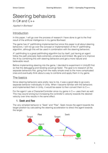
Ackerman Steering Mechanism At any angle of steering, the center point of all the circular path traced by all thewheels will coincide at a common point. It is difficult to achieve with simple linkages. However, it is applicable for low speed.
Turning Radius Turning circle of a car is the diameter of the circle described by the outside wheelswhen turning on full lock. A typical turning radius of a car is 35.5 feet.
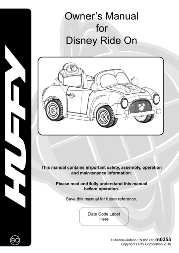
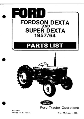
Steering Axle Inclination, Caster, and Camber Angles The angle between the vertical line and center of the king pinor steering axle, when viewed from the front of the wheel isknown as steering axle inclination or king pin inclination(0-5 degrees for trucks and 10-15 degrees on passenger cars). Caster: The angle between the vertical line and kingpin centerline in the plane of the wheel (when viewed from the side) iscalled caster angle. Camber: The angle between the centerline of the wheel and the vertical linewhen viewed from the frontPositive Camber: Upper portion is tilted outward.Negative Camber: Upper portion is tilted inward
Toe-In and Toe-Out Toe-in: The front wheels are usually turned in slightly in front so that the distancebetween front ends is slightly less than the back ends when viewed from the top.The difference between these distances is called toe-in The difference in angle between the two front wheels and the car frame duringturns. The toe-out is secured by providing the proper relationship between the steeringknuckle arms, tie rods and pitman arm.
Vehicle Dynamics and Steering Under steer: When the slip angle of front wheels is greater than the slip angle of rear wheels Over steer: When the slip angle of front wheels is lesser than the slip angle of rear wheels Neutral steer or counter steering: When the slip angle of front wheels is equal to the slipangle of rear wheels
Steering Gear Boxes
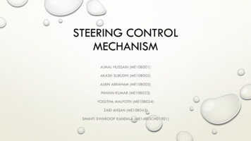
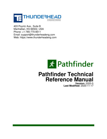
Typical Steering SystemsTruck steering systemRack-and pinion linkage:Differential steerSteering gearboxTrapezoidal tie-rodarrangementRight turnLeft turn
Ideal Steering Geometry Tie rod end connect with the relay linkage end at the ideal centre. Relay linkage is connected to the pivot of the wheel If the linkage joint is either inboard or outboard of this point, the steering geometryerror will cause a steer action as the wheels moves into jounce or rebound
Steering Geometry ErrorError due to toe changeError due to understeerSuch phenomena leads to understeer/oversteer condition.
Tire Force/Moment ConventionSAE Tire AxisThree forces and three moments atthe tire-surface interface w.r.t. ODifferent angles are selected to minimize the front type wear rather than handling.
Lateral or Cornering Force on Wheels/Tires A slip angle, 𝛼, defines the difference between the wheelplane and the direction of motion, which may arise due toinduced motion or because of an applied side force, 𝐹𝑠 . A cornering force, 𝐹𝑦𝑎 , is induced in the lateral directionbetween the tire and ground, and it is found to be appliedalong an axis off the wheel axis. This force can be treatedas the frictional force The couple 𝑇𝑎 acting on the wheel tends to turn itso its plane coincides with the direction ofmotion. Steering and suspension systems must constrainthe wheel if it is to stay, say, in the plane OA.
More on Tire Cornering Forces“ side slip is due to thelateral elasticity of thetire.” The slip angle, 𝛼, is shown here as the angle between thedirection of heading and direction of travel of the wheel (OA). The lateral force, 𝐹𝑦𝑎 , (camber angle of the wheel is zero)is generated at a tire-surface interface, and may not becollinear with the applied force at the wheel centre. Thedistance between these two applied forces is called thepneumatic trail. The self-aligning torque is given by the product of thecornering force and the pneumatic trail The induced self-aligning torque helps a steered wheelreturn to its original position after a turn.
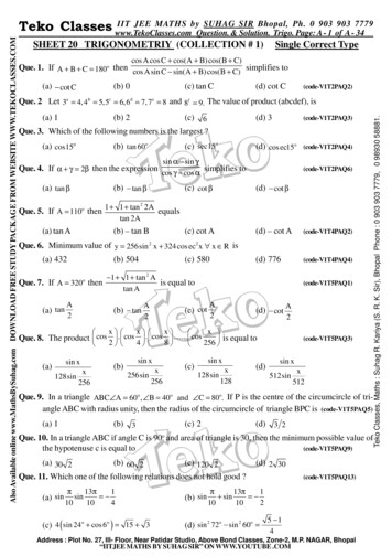
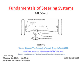
Cornering Force Data for Pneumatic Tires“linear region”Maximum cornering forces: passenger car tires: 18 degrees racing car tires: 6 degrees(Wong)Variables that impact cornering force: Normal load Inflation pressure Lateral load transfer SizeIn general, tractive (or braking) effort will reduce the cornering force that can be generatedat a given slip angle. This can be important in acceleration or braking in a turn, or inmaintaining stability subject to disturbances.
Cornering Stiffness and Coefficients The cornering stiffness will depend on tire properties such as:– tire size and type (e.g., radial, bias-ply, etc.),– number of plies,– cord angles,– wheel width, and– tread. Dependence on load is taken into accountthrough the cornering coefficient,where 𝐹𝑧 is the vertical load.
Example of Yaw InstabilityYaw instability can occur when front and rear wheels do not lock up at the same time.– Rear tires lock and ability to resist lateral force decreases.– A perturbation about the yaw center of the front axle will be developed– Yaw motion progresses with increased acceleration, with a decrease as it completes180 degree turn.Lock-up of front tires causes loss ofdirectional control, but not directionalinstability. This is because a selfcorrecting inertial moment about theyaw center of the rear axle is inducedwhenever lateral movement of the fronttires occurs.
Vehicle Dynamics and Steering Under steer: When the slip angle of front wheels is greater than the slip angle of rear wheels Over steer: When the slip angle of front wheels is lesser than the slip angle of rear wheels Neutral steer or counter steering: When the slip angle