Transcription
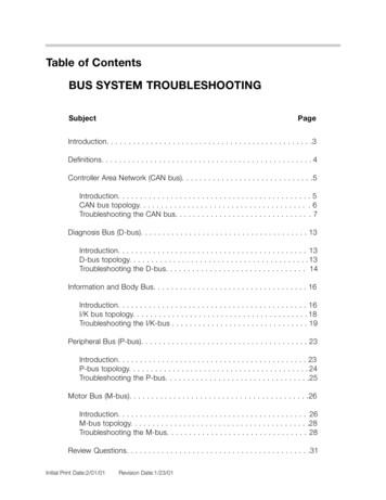
Table of ContentsBUS SYSTEM TROUBLESHOOTINGSubjectPageIntroduction. . . . . . . . . . . . . . . . . . . . . . . . . . . . . . . . . . . . . . . . . . . . . . .3Definitions. . . . . . . . . . . . . . . . . . . . . . . . . . . . . . . . . . . . . . . . . . . . . . . . 4Controller Area Network (CAN bus). . . . . . . . . . . . . . . . . . . . . . . . . . . . . .5Introduction. . . . . . . . . . . . . . . . . . . . . . . . . . . . . . . . . . . . . . . . . . . . 5CAN bus topology. . . . . . . . . . . . . . . . . . . . . . . . . . . . . . . . . . . . . . . 6Troubleshooting the CAN bus. . . . . . . . . . . . . . . . . . . . . . . . . . . . . . . 7Diagnosis Bus (D-bus). . . . . . . . . . . . . . . . . . . . . . . . . . . . . . . . . . . . . . 13Introduction. . . . . . . . . . . . . . . . . . . . . . . . . . . . . . . . . . . . . . . . . . . 13D-bus topology. . . . . . . . . . . . . . . . . . . . . . . . . . . . . . . . . . . . . . . . . 13Troubleshooting the D-bus. . . . . . . . . . . . . . . . . . . . . . . . . . . . . . . . 14Information and Body Bus. . . . . . . . . . . . . . . . . . . . . . . . . . . . . . . . . . . 16Introduction. . . . . . . . . . . . . . . . . . . . . . . . . . . . . . . . . . . . . . . . . . . 16I/K bus topology. . . . . . . . . . . . . . . . . . . . . . . . . . . . . . . . . . . . . . . . 18Troubleshooting the I/K-bus . . . . . . . . . . . . . . . . . . . . . . . . . . . . . . . 19Peripheral Bus (P-bus). . . . . . . . . . . . . . . . . . . . . . . . . . . . . . . . . . . . . . 23Introduction. . . . . . . . . . . . . . . . . . . . . . . . . . . . . . . . . . . . . . . . . . . 23P-bus topology. . . . . . . . . . . . . . . . . . . . . . . . . . . . . . . . . . . . . . . . . 24Troubleshooting the P-bus. . . . . . . . . . . . . . . . . . . . . . . . . . . . . . . . .25Motor Bus (M-bus). . . . . . . . . . . . . . . . . . . . . . . . . . . . . . . . . . . . . . . . .26Introduction. . . . . . . . . . . . . . . . . . . . . . . . . . . . . . . . . . . . . . . . . . . 26M-bus topology. . . . . . . . . . . . . . . . . . . . . . . . . . . . . . . . . . . . . . . . .28Troubleshooting the M-bus. . . . . . . . . . . . . . . . . . . . . . . . . . . . . . . . 28Review Questions. . . . . . . . . . . . . . . . . . . . . . . . . . . . . . . . . . . . . . . . . .31Initial Print Date:2/01/01Revision Date:1/23/01
BUS SYSTEM TROUBLESHOOTINGModel: All Models Using Bus SystemsProduction Date: From Model Year 1991Objectives:After completing this module you should be able to: Review the advantages of using bus systems in a vehicle. Review the various bus systems used in most BMW vehicles. Understand the operating principle of a serial bus. Review methods of troubleshooting bus lines using the diagnosis program. Recognize how to distinguish a correctly operating bus line on an oscilloscope.2Bus System Troubleshooting
IntroductionUp until the introduction of the E31, all information (e.g. RPM, temperature, vehicle speed,etc.) received and transmitted from a control unit were delivered by a dedicated wire. Asthe electronic systems used in the vehicle increased, so did the necessary wiring.Wiring each device separately became a headache for production and finding space in thebody to hold all of this wiring was becoming difficult, not to mention the effect on reliabilityand ever more complicated troubleshooting.It soon became clear that a solution must be found, that solution was the bus system.The benefits of the bus system are: Greater reliability by reducing the number of wiring, connectors and components. Reduction in wire harness size by decreasing the number of interfaces between controlunits to one or two wires. Multiple utilization of sensors by transmitting information from one control unit to thenext. Flexibility in system configuration and future applications. Reduction in costs for components, assembly and troubleshooting.Today s vehicles have several bus systems that are divided according to groups of controlunits which share common functionality and information. Currently the bus systems in useare: CAN-busD-busI-busK-busP-busM-busIn the very near future the the complexity and number of control units in the vehicle willchange, as will the structure and construction of the bus systems. However, the principleof operation will remain similar. Efficient troubleshooting of the new bus systems will rely ona thorough understanding and knowledge of the systems currently in use.3Bus System Troubleshooting
DefinitionsBus LineA bus line is a group signal line that transmits serial data in both directions. It may consistof one wire or two. All control units are connected in parallel in current bus systems, thismeans that the information sent can be heard by all of the connected units.Bus SubscriberAny control module connected to a bus line. e.g. DME, IKE, GM, etc.GatewayA Gateway module provides a link between different bus lines to provide a means of sending information from a subscriber of one bus line to the subscriber of another. The Gatewaymodule recognizes from the receiver address whether a message is to be routed throughthe gateway or not. e.g. IKE, KOMBI.Master controllerA Master Controller of a bus system provides the operating voltage and wake up signals tothe subscriber modules. This task may also be performed by several Standby Masterswithin a bus system. e.g. GM, LCM.Serial DataSerial means one event at a time. In data transmission, the technique of time division isused to separate bits of data sent. The messages sent over a bus are configured serially.Each message consists of:1.2.3.4.5.6.Transmitter addressLength of dataReceiver addressCommand or InformationDetailed description of message (data)Summary of transmitted information (check sum)All of the connected control units will receive the information but only the unit in the addresswill accept and react to the data.Note: This message format is not used for the CAN Bus.TopologyIn the context of communication networks, Topology describes the configuration orarrangement of a network.4Bus System Troubleshooting
Controller Area Network (CAN Bus)IntroductionThe CAN bus is a serial communications bus in which all connected control units can sendas well as receive information. Data over the CAN operates at a rate of up to 500 K/bps(kilobits per second).The CAN protocol was originally developed by Intel and Bosch in 1988 for use in the automotive industry to provide a standardized, reliable and cost-effective communications busfor a cars electronics to combat the increasing size of wiring harnesses.TMThe CAN bus was originally introduced on BMW automobiles in the 1993 740i/iL as a datalink between the DME and AGS control units.Data transmitted from any subscriber on a CAN bus does not contain addresses of thetransmitting or receiving control unit. Instead, the content of the message (RPM, TD,Temp,etc) is labeled by an identifier code that is unique throughout the CAN. All of the subscribers receive the message and each one checks the message to see if it is relevant tothat particular control unit.If the message is relevant then it will be processed, if not, it will be ignored. The identifiercode also determines the priority of the message. In a case where two control unitsattempt to send a message over a free bus line, the message with the higher priority will betransmitted first. The protocol of the CAN ensures that no message is lost, but stored bythe sender and then re-transmitted later when it is possible.5Bus System Troubleshooting
CAN Bus TopologyThe CAN bus consists of two twisted copper wires. Each wire contains an opposing signal with the exact same information (CAN-High, CAN-Low). The opposing signals transmitted through the twisted wire serve to suppress any electrical interference. Early CANbus wiring included a grounded shield around the two wires, later vehicles discarded theshield in favor of the unshielded twisted pair wiring.Due to the linear structure of the network, the CAN bus is available for other modules in theevent of a disconnected or failed control unit. This is referred to as a Tree structure witheach control unit occupying a branch.Example of Tree structure95-97 E38 750iLTrunkBranchesAs previously mentioned, the CAN bus initially was used as a high speed communicationlink between the DME and AGS control units.With the introduction of the E38 750iL (95 M.Y.), the CAN bus was expanded to include theEML and DSC control modules. The 750iL made exclusive use of the star coupler to linkthe individual CAN bus ends to a common connector.The 1998 model year introduced new users of the CAN bus. The instrument cluster andthe steering angle sensor were linked to expand the signal sharing capabilities of the vehicle.The 1999 750iL was the last vehicle to use the shielded cable, after which the entire CANbus went to twisted pair wiring.Always refer to the ETM to determine the exact wiring configuration for a specific model.6Bus System Troubleshooting
INSTRUMENTCLUSTER80GS 2060MS 43.04012011UNLEADED GASOLINE ONLY20803100120 m/h5030 20 15712MPHmiles1 234BRAKEABS5CAN BUSSPLICE CONNECTIONSFOR TWISTED PAIR CANOn most current models the CAN bus providesdata exchange between the followingmodules: DMEEML (750iL)AGS/EGSASC/DSCIKE/KOMBILEWLEWMK 60On models that use twisted pair, the wire color of the CAN bus is uniform throughout thevehicle with: CAN-Low GE/BR and CAN-High GE/SW or GE/RT. Shielded wiring is easilyidentified by the black sheath surrounding the CAN bus.Troubleshooting the CAN BusThe failure of communication on the CAN bus can be caused by several sources: Failure of the CAN bus cables.Failure of one of the control units attached to the CAN.Failure of the voltage supply or ground to individual modules.Interference in the CAN bus cables.Failure of a CAN bus resistor.Failure of the CAN bus cablesThe following faults can occur to the CAN bus wiring: CAN-H/L interruptedCAN-H/L shorted to battery voltageCAN-H/L shorted to groundCAN-H shorted to CAN-LDefective plug connections (damaged, corroded, or improperly crimped)7Bus System Troubleshooting
The voltage of the CAN bus is divided betweenthe two data lines: CAN-High and CAN-Lowfor an average of 2.5V per line. The voltagemeasurement is taken from each data line toground. CAN does not utilize a MasterController, each module on the CAN providesoperating voltage.The fact that 2.5V are present does not meanthat the CAN bus is fault free, it just means thatthe voltage level is available to support communication.PrintChangeEndServicesHelpBMW Test system MultimeterFreeze image2.35 V2.65 mperatureCurrent2ACurrent50ACurrent1000AMFK 1MFK 2oSystem voltageRotation speedCCurrent probe MinimumMaximum- -Diode easurementEffective valueautomaticMultimeterStimulate 10 ementsTerminal resistors: are used in the CAN bus circuit to establish the correct impedance toensure fault free communication. A 120 Ohm resistor is installed in two control units of theCAN between CAN-H and CAN-L. Because the CAN is a parallel circuit, the effective resistance of the complete circuit is 60 Ohms. On some vehicles there is a jumper wire that connects the two parallel branches together, others have an internal connection at the instrument cluster.The resistance is measured by connecting the appropriate adapter to any of the moduleson the CAN and measuring the resistance between CAN-L and CAN-H. The resistanceshould be 60 Ohms. The CAN bus is very stable and can continue to communicate if theresistance on the CAN bus is not completely correct; however, sporadic communicationfaults will occur.The terminal resistors are located in theASC/DSC control unit and either the instrumentcluster or in the DME.Early 750iL vehicles that used the star connectorhave a separate external resistor which connectCAN-H and CAN-L together.Modules which do not have the terminal resistorcan be checked by disconnecting the moduleand checking the resistance directly between thepins for CAN-H and CAN-L. The value at thesecontrol units should be between 10kOhms and50kOhms.124000038Bus System Troubleshooting
If there are CAN communication faults that use the term Timeout this refers to a modulenot being able to communicate with another on the bus. Each module on the CAN bus willattempt communication several times. If unsuccessful, the module will store a Timeout or CAN bus fault and determine that there is a problem with either the bus line or the module that it is trying to communicate with.These types of faults may indicate a problem with the bus wiring, interference, missing dataor failure of the communication module of an individual control unit.Checking the CAN lines is carried out just like any other wiring. Perform continuity testsbetween the connections of different modules (all modules disconnected) without forgettingto make sure that the two CAN lines have not shorted to ground or to each other. It isrecommended to use the Wire Test in Preset Measurements which is moresensitive than just a resistance check.If Voltage level and the wire test are O.K, then looking at the communication signal may beuseful.The following are some examples of scope patterns that may be observed when checkingthe CAN bus.PrintChangeEndServicesHelpBMW Test system Oscilloscope displayCursor 1A [V]MemoryFreeze ImageCursor 2B [V] VChannel B5.0 4.04.0 3.03.0 2.02.05.0 1.01.04.00.03.0 -1.00Triggerl2.0 -2.0 ev1.0 -3.0e0.0 -4.0 asurmentsZoomAmplitudeChannel ACAN-L (low)Flat line should average 2.5volts with signal line beingpulled low for communication.AmplitudeChannel BTime valueCAN-H (high)StimulateFlat line should average 2.5volts with signal line beingpulled high for communication.Example of correctly operating CAN busCorrect communication on the CAN bus occurs in sporadic bursts with short periods ofsteady voltage.9Bus System Troubleshooting
Examples of Defective CAN bus signalsPrintChangeEndServicesHelpBMW Test system Oscilloscope displayCursor 1A [V]MemoryPrintChangeEndServicesHelpBMW Test system Oscilloscope displayFreeze ImageCursor 2Cursor 1A [V]B [V] VMemoryFreeze ImageCursor 2B [V] VChannel B 4.03.02.0 3.01.0 2.00.05.0 1.00-1.04.0-2.03.0 -1.0Triggerl2.0 -2.0 ev1.0 -3.0e0.0 -4.0 udeChannel AAmplitudeChannel BChangeEndCursor 3.0Presetmeasurments-1.0MultimeterHelpTriggerl-8 -2.0 ev-12 -3.0e-16 -4.0 l-2.0ServicesMemory3.0-4.0ms4.02.0-3.0BMW Test system Oscilloscope displayA [V]16Time valueRapid Constant fixed duty cycle for10 seconds.This example represents the output signalproduced by an AGS module that is isolated from the bus. This pattern times outafter 10 seconds and remains a flat line at2.5 volts until the key is cycled and theevent is repeated.PrintChannel orsmsPresetmeasurmentsFlat line at 2.5 voltsIf a continuous flat line is present at one orboth CAN lines of a particular control unit,this may indicate that the CAN is open tothat particular module. The module mayhave timed out and is waiting for a signalfrom another control unit. Check the CANbus at other points to see if communication is occurring else where on the bus.PrintChangeEndServicesHelpFreeze ImageCursor 2B [V] V 4.04.0 3.03.0 2.02.05.0 1.01.04.00.03.0 -1.0Cursor 1A [V]0Triggerl2.0 -2.0 ev1.0 -3.0e0.0 -4.0 3.0OscilloscopesettingMemoryFreeze ImageCursor 2B [V] VStimulatorsmsBus System TroubleshootingChannel B 4.05.0ZoomAmplitudeChannel AAmplitudeChannel BTime value4.0 3.03.0 2.02.05.0 1.04.00.03.0 -1.0-1.0-4.0PresetmeasurmentsTriggerl2.0 -2.0 ev1.0 -3.0e0.0 -4.0 l-3.0Stimulate01.0-2.0Constant fixed duty no time limitAll of the other control units with theexception of most current AGS moduleswill continue to try and send informationeven though the control unit has alreadystored a Timeout or CAN fault. This typeof signal may only be seen if a section orall of the CAN bus is disconnected.10Time valueBMW Test system Oscilloscope display5.03.0AmplitudeChannel BStimulateChannel B-4.0ZoomAmplitudeChannel oscopesettingStimulatorsmsZoomAmplitudeChannel AAmplitudeChannel BTime valueStimulatePresetmeasurmentsCAN High shorted to CAN LowIf the CAN bus lines were to becomeshorted to one another then the signalswould cancel each other out and effectively be a flat line.
Failure of one of the control units attached to the CAN.Each control unit connected to the CAN has an integrated communication module thatmakes it possible for that control unit to exchange information on the CAN. Failure of acontrol unit normally triggers a fault code in the other control units connected to the bus.There are instances where failure of a module may paralyze or take down the entire CANbus. This scenario would be evident by CAN faults stored in every control unit on the bus.In order to isolate the defective control unit, the control units can be disconnected one at atime while monitoring the status of the CAN using a Voltmeter or oscilloscope. This can befurther reinforced by clearing the faults of the remaining control units and then reading themagain. If the disconnected control module is the defective one, the faults will onlypoint to communication with that interrupted module and no one else.As a quick check on vehicles produced after 9/97 (3/98 for the E39 528i) that have the CANconnection to the Instrument cluster, the indicators provide visual indication of whethercommunication is restored.If for example the tachometer and temperature display are plausible then communication isoccurring between the DME and IKE/KOMBI. Other indicators such as transmission rangeor the DSC light may give clues to the communication status with those control units.Once the module has been replaced and coded or programmed, perform the CAN bus TestModule in each control unit to ensure that communication is OK.E38/E39 Style diagnosis test modulePrintChangeEndE46 Style diagnosis test moduleServicesChangePrintBMW Diagnosis CAN CONNECTIONServicesEndBMW Diagnosis Test informationCAN interfaceNote:Data transmission on the CAN bus isdisturbed.CAN-BusCausesThe failure of communication on the CAN-bus (i.e fault code entries relating tobus communication in the individual control modules may be caused by thefollowing:X18836Possible causes of fault:-Short circuit between wiresCAN H and CAN LCAN H and groundCAN L and power supplyDefective or incorrect input circuit inABS/DSC control unitIncorrect coding of control unit- Breaks in line (open circuits) or short-circuits in the communication lines- Interference voltages in the vehicle electrical system caused for instance bydefective ignition coils or ground connectionsCAN-H- Failure of the communication modules in the individual control 117611X1658R33A2Instrument clusterInstruction:If the CAN bus is O.K. , replace theABS/DSC control module- Failure of the voltage supply to individual control modules. A slowly droppingbattery voltage when the battery is almost discharged can also lead to fault codeB1214 M0CAN/Message 080.5GE/SWSteering angle sensorX11176Signal from instrument cluster controlmodule absent or disturbed.Check line to instrument cluster controlmodule andcontinue troubleshooting at instrumentcluster control module.NoteFunctionSelection07400001DocumentsTest ScheduleTISMeasuringSystemControl unitFunctionsNoteFunctionSelectionDocumentsTest ScheduleTISMeasuringSystemControl unitFunctions0740000211Bus System Troubleshooting
Failure of the voltage supply to individual modules.A slowly dropping battery voltage or a vehicle with discharged battery can lead to sporadiccommunication faults in various control units on the bus. The reason is that not all controlunits will switch off communication at the same voltage level leaving some modules still trying to communicate. Always verify a properly charged battery and charging system beforebeginning troubleshooting on the CAN.Interference in the CAN bus cables.Interference will have a similar effect to shorting or disturbing the CAN bus wiring.Excessive interference created by a defective alternator or aftermarket devices such as cellphones or amplifiers may induce a voltage into the CAN bus line and disrupt communication. This type of interruption may be intermittent and faults may only be stored in somemodules and not in others. These faults are often difficult to reproduce. Begin by eliminating any problems with the CAN bus wiring itself and verify that the generator is operating fault free. Isolate any aftermarket wiring in the vehicle and see if the fault returns.ProgrammingDuring programming it should be noted that the module being programmed will not becommunicating and therefore the other control units on the bus will store faults. Thesefaults stored during programming should be deleted and then the fault memory should beread again to verify that they do not return. An incorrectly programmed module results inCAN faults that are not able to be cleared. Remember to always verify the correctProgrammed Part Number after programming.12Bus System Troubleshooting
Diagnosis Bus (D-bus)IntroductionThe D-bus is a serial communications bus which can transmit data between the BMW DISor MoDiC and the connected control units. The control unit to be subject to diagnosis isselected by sending a diagnosis telegram to the control unit address. By request from thetester, the control unit can transmit information and the contents of the fault memory or activate a control unit output. The D-bus is only active when the DIS or MoDiC is connectedto the diagnostic socket and communicating.The D-bus is actually the oldest bus system used in BMW vehicles, it was introduced in1987 as TXD which provided communication between DME and the Sun 2013 ServiceTester. The D-bus is still referred to as TXD in the ETM.Data over the D-bus currently operates at a rate of up to 9.6 Kbps (bits per second).D-Bus TopologyThe D-bus (TXD) is connected to various control units that are diagnosed using DIS orMoDiC. Earlier vehicles also used a second diagnosis line called RXD to allow the testequipment to establish communication. RXD is not a bus line but a one way communication link used to wake up the diagnosis of the connected control unit.On vehicles produced up to model year 2001 and use the 20 pin under-hood diagnosticconnector, the locations of the two links are: RXD-Pin 15TXD-Pin 20Later control modules (from 1997) no longer required the separate RXD to establish communication, (DS2 protocol) so Pin 15 was removed from the Diagnostic socket of mostvehicles.To satisfy the requirements of OBD II, in 1995 a standardized connector was installed insideof all vehicles. This connector has to provide access to all powertrain modules via an aftermarket scan tool. TXD II (pin 17) was introduced as a separate communication line exclusive to DME (ECM), AGS (TCM) and EML. TXD II is technically identical to the D bus (TXD).On vehicles that use only the 16 pin OBD connector in the vehicle, TXD is installed in pin 8.TXD II remains in pin 7.13Bus System Troubleshooting
The term D bus was actually coined with the introduction of the E38 and the expanded useof bus systems in the vehicle. On vehicles from E38 on (except Z3), the D-bus is directlywired to: ASC/DSCEDC (if equipped)LEWIKE/KOMBI12400005The IKE/KOMBI serves as the gateway for the D-bus that converts the telegram format ofthe I/K bus to the format of the D-bus.The wire color of the D-bus is uniform throughout the vehicle, it is a single WS/VI wire.Troubleshooting the D-BusThe failure of communication with one or several control units via the D-bus can be causedby: 14Failure of the D-bus cable or its individual connections.Failure of the IKE/KOMBI control unit.Failure of the I/K or P-bus or its individual connections.Failure of the voltage supply or ground to individual modules.Interference in the D-bus cable.Bus System Troubleshooting
Failure of the D-bus cableThe following faults can occur to the D-bus wiring: D-bus interruptedD-bus shorted to battery voltageD-bus shorted to groundDefective plug connections (damaged, corroded, or improperly crimped)The operating voltage of the D-bus is 12 volts. The voltage measurement is taken fromeach data line connection to ground. Each module on the D-bus provides its own voltage.The fact that 12V are present does not mean that the D-bus is fault free, it just means thatthe voltage level is sufficient to support communication.Minimum voltages that are needed for fault free communication are: D-bus (TXD)/TXD II 2.0VRXD (if equipped) 10.5VIf problems are encountered trying to establish communication consider first: Battery charge level of the vehicle. Maintain a battery charger on the vehicle at all timesduring diagnosis. Always check that the diagnosis head and connection are OK before working througha test module for lack of communication.On vehicles that use the IKE/KOMBI as a gateway:ChangePrintServicesEndBMW Diagnosis Test informationX19527 OBDII socket30F25Bus test7.5A50Test preconditions: Always check that the diagnosis cable and tester are OKbefore working through the test module. If necessary, the diagnosis procedureshould be carried out on another vehicle or the diagnosis cable checked bymeans of a self-test. The self test-diagnosis cable (Selection:administration) checks whether the diagnosis cable and the diagnosis interfacein the tester ar OK. For this purpose, the diagnosis cable must be connectedto the test socket at the rear of the tester.F15157.5AX10015X1001530 25Test procedure : The bus systems (I/K and D-bus) are tested in the testmodule. The following control units are addressed as part of the test:DME/DDE, ABS/ASC/DSC,KOMBI (insrument cluster), IHKA/IHKR/IHR, ZKE,RADIO, BM/MID and LCM/LSZ. The identification of the control unit is read outfor testing purposes.15 150.5RT/SW0.75GN/WSX183TXD116If identification of the vehicle is carried out by the diagnostics withoutany problems then the D-bus isOK.1Bus test E38/39/46/52/53/Message 01Data transfer from the tester to the D-bus,K-bus and I-bus is tested in the followingtest module.Take note of the information provided inthe functional description "Bus systemand bus test"!431L 30.5BRIf several control units are not recognized this indicates that a buslink is defective. Continue troubleshooting using the test modulesfor those particular bus systems.NoteFunctionSelectionDocumentsTest ScheduleTISMeasuringSystemControl unitFunctions07400100D-bus test module15Bus System Troubleshooting
Information and Body Bus (I and K bus)IntroductionThe I and K buses are a serial communications bus in which all connected control units cansend as well as receive information over one wire. The I and K bus are technically identical, the only difference is their use by model. From this point forward they will be referredto as the I/K bus and differences will be pointed out separately.The I bus was originally introduced in the E31 to provide a standardized, reliable and costeffective communications bus for a cars electronics to combat the increasing size of wiringharnesses.The E38 expanded the use of bussing in BMW vehicles by adding three more busses (K,P and M) and adding more control units to the network.The data transfer rate is approximately 9.6Kbps (bits per second).The I/K-bus is always active when terminal R is switched on. If the bus line is quiet morethan 60 seconds, all of the control modules will go into Sleep Mode.When receiving messages over the bus line, the control unit first determines if the messageis error free before accepting it.The information sent over the bus is configured serially. Each message consists of:1. Transmitter address (8 bit address) The senders name.2. Length of data (number of following message bytes) How long the sender will speak.3. Receiver address (8 bit address) Whom the sender wishes to speak to.4. Command or Information What the sender wants done.5. Detailed description of message (maximum 32 bytes of data) How the sender wants it done.6. Summary of transmitted information (check sum) The sender summarizes everything said.16Bus System Troubleshooting
The sender of the message then waits (100ms) for an acknowledgement that the messagewas received.All of the connected control units will receive the information, but only the moduleaddressed will accept and react to the data.The rules for communication on the bus line are: Only one module speaks at a time.Everybody speaks at the same speed.Messages are acknowledged by the recipient.The message is repeated if the addressed module fails to respond.The Master Controller has priority.Quit sending message after 5 failed attempts.Communication between busses: On vehicles equipped with an I-bus (E38, E39, E53High) messages to be sent back and forth between the K-bus and I-bus have to be transferred via a Gateway. This Gateway is the IKE. The IKE determines by the address of themessage recipient whether the message needs to be passed along to the other bus. TheD-Bus and CAN-Bus also utilize the IKE or KOMBI as a gateway.Polling: Each module on the I/K bus is informed by a message from the Master Controlleras to the ready status of all of the other connected modules. The modules polled areaccording to the coding of the Master Controller. Every 30 seconds after KL R i
Signal from instrument clustercontrol module absent ordisturbed. Check line to instrument clustercontrol module and continue troubleshooting at instrument clustercontrol module. A2 R33 X18836 X11176 CAN-H CAN-H X18832 X18832 X1658 X11176 Instrument cluster Steering angle sensor 0.5 GE/SW 0.5 GE/SW 24 3 11 67 6) # " " ?@ # " "