Transcription
ARM Cortex -M4 Processor Revision r0p1Technical Reference ManualCopyright 2009, 2010, 2013 ARM Limited. All rights reserved.ARM DDI 0439D (ID061113)
ARM Cortex-M4 ProcessorTechnical Reference ManualCopyright 2009, 2010, 2013 ARM Limited. All rights reserved.Release InformationThe following changes have been made to this book.Change HistoryDateIssueConfidentialityChange22 December 2009ANon-Confidential, Restricted AccessFirst release for r0p02 March 2010BNon-ConfidentialSecond release for r0p029 June 2010CNon-ConfidentialFirst release for r0p111 June 2013DNon-ConfidentialSecond release for r0p1Proprietary NoticeWords and logos marked with or are registered trademarks or trademarks of ARM in the EU and other countries,except as otherwise stated below in this proprietary notice. Other brands and names mentioned herein may be thetrademarks of their respective owners.Neither the whole nor any part of the information contained in, or the product described in, this document may beadapted or reproduced in any material form except with the prior written permission of the copyright holder.The product described in this document is subject to continuous developments and improvements. All particulars of theproduct and its use contained in this document are given by ARM in good faith. However, all warranties implied orexpressed, including but not limited to implied warranties of merchantability, or fitness for purpose, are excluded.This document is intended only to assist the reader in the use of the product. ARM shall not be liable for any loss ordamage arising from the use of any information in this document, or any error or omission in such information, or anyincorrect use of the product.Where the term ARM is used it means “ARM or any of its subsidiaries as appropriate”.Confidentiality StatusThis document is Non-Confidential. The right to use, copy and disclose this document may be subject to licenserestrictions in accordance with the terms of the agreement entered into by ARM and the party that ARM delivered thisdocument to.Product StatusThe information in this document is Final (information on a developed product).Web Addresshttp://www.arm.comARM DDI 0439DID061113Copyright 2009, 2010, 2013 ARM Limited. All rights reserved.Non-Confidentialii
ContentsARM Cortex-M4 Processor Technical ReferenceManualPrefaceAbout this book . viFeedback . ixChapter 1Introduction1.11.21.31.41.51.6Chapter 2About the functions . 2-2Interfaces . 2-5Programmers Model3.13.23.33.43.53.63.73.83.9ARM DDI 0439DID0611131-21-31-41-51-61-9Functional Description2.12.2Chapter 3About the processor .Features .Interfaces .Configurable options .Product documentation .Product revisions .About the programmers model . 3-2Modes of operation and execution . 3-3Instruction set summary . 3-4System address map . 3-14Write buffer . 3-17Exclusive monitor . 3-18Bit-banding . 3-19Processor core register summary . 3-21Exceptions . 3-23Copyright 2009, 2010, 2013 ARM Limited. All rights reserved.Non-Confidentialiii
ContentsChapter 4System Control4.14.24.3Chapter 5About system control . 4-2Register summary . 4-3Register descriptions . 4-5Memory Protection Unit5.15.25.3Chapter 6About the MPU . 5-2MPU functional description . 5-3MPU programmers model . 5-4Nested Vectored Interrupt Controller6.16.26.3Chapter 7About the NVIC . 6-2NVIC functional description . 6-3NVIC programmers model . 6-4Floating Point Unit7.17.27.3Chapter 8Debug8.18.28.3Chapter 9ARM DDI 0439DID061113About the ITM . 10-2ITM functional description . 10-3ITM programmers model . 10-4Trace Port Interface Unit11.111.211.3Appendix AAbout the DWT . 9-2DWT functional description . 9-3DWT Programmers Model . 9-4Instrumentation Trace Macrocell Unit10.110.210.3Chapter 11About debug . 8-2About the AHB-AP . 8-6About the Flash Patch and Breakpoint Unit (FPB) . 8-9Data Watchpoint and Trace Unit9.19.29.3Chapter 10About the FPU . 7-2FPU Functional Description . 7-3FPU Programmers Model . 7-9About the Cortex-M4 TPIU . 11-2TPIU functional description . 11-3TPIU programmers model . 11-5RevisionsCopyright 2009, 2010, 2013 ARM Limited. All rights reserved.Non-Confidentialiv
PrefaceThis preface introduces the Cortex-M4 Technical Reference Manual (TRM). It contains thefollowing sections: About this book on page vi. Feedback on page ix.ARM DDI 0439DID061113Copyright 2009, 2010, 2013 ARM Limited. All rights reserved.Non-Confidentialv
PrefaceAbout this bookThis book is for the Cortex-M4 processor.Product revision statusThe rnpn identifier indicates the revision status of the product described in this manual, where:rnIdentifies the major revision of the product.pnIdentifies the minor revision or modification status of the product.Intended audienceThis manual is written to help system designers, system integrators, verification engineers, andsoftware programmers who are implementing a System-on-Chip (SoC) device based on theCortex-M4 processor.Using this bookThis book is organized into the following chapters:Chapter 1 IntroductionRead this for a description of the components of the processor, and of the productdocumentation.Chapter 2 Functional DescriptionRead this for a description of the functionality of the processor.Chapter 3 Programmers ModelRead this for a description of the processor register set, modes of operation, andother information for programming the processor.Chapter 4 System ControlRead this for a description of the registers and programmers model for systemcontrol.Chapter 5 Memory Protection UnitRead this for a description of the Memory Protection Unit (MPU).Chapter 6 Nested Vectored Interrupt ControllerRead this for a description of the interrupt processing and control.Chapter 7 Floating Point UnitRead this for a description of the Floating Point Unit (FPU)Chapter 8 DebugRead this for information about debugging and testing the processor.Chapter 9 Data Watchpoint and Trace UnitRead this for a description of the Data Watchpoint and Trace (DWT) unit.Chapter 10 Instrumentation Trace Macrocell UnitRead this for a description of the Instrumentation Trace Macrocell (ITM) unit.Chapter 11 Trace Port Interface UnitRead this for a description of the Trace Port Interface Unit (TPIU).ARM DDI 0439DID061113Copyright 2009, 2010, 2013 ARM Limited. All rights reserved.Non-Confidentialvi
PrefaceAppendix A RevisionsRead this for a description of the technical changes between released issues of thisbook.GlossaryThe ARM Glossary is a list of terms used in ARM documentation, together with definitions forthose terms. The ARM Glossary does not contain terms that are industry standard unless theARM meaning differs from the generally accepted meaning.See ARM Glossary, eg0014-/index.html.Typographical ConventionsConventions that this book can use are described in: Typographical.TypographicalThe typographical conventions are:italicHighlights important notes, introduces special terminology, denotesinternal cross-references, and citations.boldHighlights interface elements, such as menu names. Denotes signalnames. Also used for terms in descriptive lists, where appropriate.monospaceDenotes text that you can enter at the keyboard, such as commands, fileand program names, and source code.monospaceDenotes a permitted abbreviation for a command or option. You can enterthe underlined text instead of the full command or option name.monospace italicDenotes arguments to monospace text where the argument is to bereplaced by a specific value.monospaceDenotes language keywords when used outside example code. and Enclose replaceable terms for assembler syntax where they appear in codeor code fragments. For example:ADD Rd, Rn, op2 Additional readingThis section lists publications by ARM and by third parties.See Infocenter, http://infocenter.arm.com, for access to ARM documentation.ARM publicationsThis book contains information that is specific to this product. See the following documents forother relevant information: ARM v7-M Architecture Reference Manual (ARM DDI 0403). ARM Cortex-M4 Integration and Implementation Manual (ARM DII 0239). ARM ETM-M4 Technical Reference Manual (ARM DDI 0440). ARM AMBA 3 AHB-Lite Protocol (v1.0) (ARM IHI 0033). ARM AMBA 3 APB Protocol Specification (ARM IHI 0024).ARM DDI 0439DID061113Copyright 2009, 2010, 2013 ARM Limited. All rights reserved.Non-Confidentialvii
Preface ARM CoreSight Components Technical Reference Manual (ARM DDI 0314).ARM Debug Interface v5 Architecture Specification (ARM IHI 0031).Cortex-M4 Lazy Stacking and Context Switching Application Note 298 (ARM DAI0298).Other publicationsThis section lists relevant documents published by third parties: IEEE Standard Test Access Port and Boundary-Scan Architecture 1149.1-2001 (JTAG). IEEE Standard IEEE Standard for Binary Floating-Point Arithmetic 754-2008.ARM DDI 0439DID061113Copyright 2009, 2010, 2013 ARM Limited. All rights reserved.Non-Confidentialviii
PrefaceFeedbackARM welcomes feedback on this product and its documentation.Feedback on this productIf you have any comments or suggestions about this product, contact your supplier and give: The product name. The product revision or version. An explanation with as much information as you can provide. Include symptoms anddiagnostic procedures if appropriate.Feedback on contentIf you have comments on content then send an e-mail to errata@arm.com. Give: The title The number, ARM DDI 0439D. The page numbers to which your comments apply A concise explanation of your comments.ARM also welcomes general suggestions for additions and improvements.NoteARM tests the PDF only in Adobe Acrobat and Acrobat Reader, and cannot guarantee thequality of the represented document when used with any other PDF reader.ARM DDI 0439DID061113Copyright 2009, 2010, 2013 ARM Limited. All rights reserved.Non-Confidentialix
Chapter 1IntroductionThis chapter introduces the processor and instruction set. It contains the following sections: About the processor on page 1-2. Features on page 1-3. Interfaces on page 1-4. Configurable options on page 1-5. Product documentation on page 1-6. Product revisions on page 1-9.ARM DDI 0439DID061113Copyright 2009, 2010, 2013 ARM Limited. All rights reserved.Non-Confidential1-1
Introduction1.1About the processorThe Cortex-M4 processor is a low-power processor that features low gate count, low interruptlatency, and low-cost debug. The Cortex-M4 includes optional floating point arithmeticfunctionality (see Chapter 7 Floating Point Unit). The processor intended for deeply embeddedapplications that require fast interrupt response features.ARM DDI 0439DID061113Copyright 2009, 2010, 2013 ARM Limited. All rights reserved.Non-Confidential1-2
Introduction1.2FeaturesThe Cortex-M4 processor incorporates:ARM DDI 0439DID061113 A processor core. A Nested Vectored Interrupt Controller (NVIC) closely integrated with the processor coreto achieve low latency interrupt processing. Multiple high-performance bus interfaces. A low-cost debug solution with the optional ability to:— Implement breakpoints and code patches.— Implement watchpoints, tracing, and system profiling.— Support printf() style debugging.— Bridge to a Trace Port Analyzer (TPA). An optional Memory Protection Unit (MPU). An optional Floating Point Unit (FPU).Copyright 2009, 2010, 2013 ARM Limited. All rights reserved.Non-Confidential1-3
Introduction1.3InterfacesThe processor has the following external interfaces: Multiple memory and device bus interfaces. ETM interface. Trace port interface. Debug port interface.ARM DDI 0439DID061113Copyright 2009, 2010, 2013 ARM Limited. All rights reserved.Non-Confidential1-4
Introduction1.4Configurable optionsYou can configure your Cortex-M4 implementation to include the following optionalcomponents as Table 1-1 shows:Table 1-1 Optional implementation componentsComponentDescriptionMPUSee Chapter 5 Memory Protection UnitFPBSee Chapter 8 DebugDWTSee Chapter 9 Data Watchpoint and Trace UnitITMSee Chapter 10 Instrumentation Trace Macrocell UnitETMSee the ETM-M4 Technical Reference ManualAHB-APSee Chapter 8 DebugHTM interfaceSee AHB Trace Macrocell interface on page 2-7TPIUSee Chapter 11 Trace Port Interface UnitWICSee Low power modes on page 6-3Debug PortSee Debug Port AHB-AP interface on page 2-7FPUSee Chapter 7 Floating Point UnitBit-bandingSee Bit-banding on page 3-19Constant AHB controlSee Bus interfaces on page 2-5NoteYou can only configure trace functionality in the following combinations: No trace functionality. ITM and DWT. ITM, DWT, and ETM. ITM, DWT, ETM, and HTM.You can configure the features provided in the DWT independently.ARM DDI 0439DID061113Copyright 2009, 2010, 2013 ARM Limited. All rights reserved.Non-Confidential1-5
Introduction1.5Product documentationThis section describes the processor books, how they relate to the design flow, and the relevantarchitectural standards and protocols.See Additional reading on page vii for more information about the books described in thissection.1.5.1DocumentationThe Cortex-M4 documentation is as follows:Technical Reference ManualThe Technical Reference Manual (TRM) describes the functionality and theeffects of functional options on the behavior of the Cortex-M4 processor. It isrequired at all stages of the design flow. Some behavior described in the TRMmight not be relevant because of the way that the Cortex-M4 processor isimplemented and integrated. If you are programming the Cortex-M4 processorthen contact: The implementer to determine:—The build configuration of the implementation.—What integration, if any, was performed before implementing theprocessor.The integrator to determine the pin configuration of the SoC that you areusing.Integration and Implementation ManualThe Integration and Implementation Manual (IIM) describes: The available build configuration options and related issues in selectingthem. How to configure the Register Transfer Level (RTL) with the buildconfiguration options. How to integrate the processor into a SoC. This includes a description ofthe integration kit and describes the pins that the integrator must tie off toconfigure the macrocell for the required integration. How to implement the processor into your design. This includesfloorplanning guidelines, Design for Test (DFT) information, and how toperform netlist dynamic verification on the processor. The processes to sign off the integration and implementation of the design.The ARM product deliverables include reference scripts and information aboutusing them to implement your design.Reference methodology documentation from your EDA tools vendorcomplements the IIM.The IIM is a confidential book that is only available to licensees.ETM-M4 Technical Reference ManualThe ETM-M4 TRM describes the functionality and behavior of the Cortex-M4Embedded Trace Macrocell. It is required at all stages of the design flow.Typically the ETM-M4 is integrated with the Cortex-M4 processor prior toimplementation as a single macrocell.ARM DDI 0439DID061113Copyright 2009, 2010, 2013 ARM Limited. All rights reserved.Non-Confidential1-6
IntroductionCortex-M4 User Guide Reference MaterialThis document provides reference material that ARM partners can configure andinclude in a User Guide for an ARM Cortex-M4 processor. Typically: Each chapter in this reference material might correspond to a section in theUser Guide. Each top-level section in this reference material might correspond to achapter in the User Guide.However, you can organize this material in any way, subject to the conditions ofthe licence agreement under which ARM supplied the material.1.5.2Design FlowThe processor is delivered as synthesizable RTL. Before it can be used in a product, it must gothrough the following process:ImplementationThe implementer configures and synthesizes the RTL.Integration The integrator connects the implemented design into a SoC. This includesconnecting it to a memory system and peripherals.ProgrammingThe system programmer develops the software required to configure andinitialize the processor, and tests the required application software.Each stage in the process can be performed by a different party. Implementation and integrationchoices affect the behavior and features of the processor.For MCUs, often a single design team integrates the processor before synthesizing the completedesign. Alternatively, the team can synthesise the processor on its own or partially integrated,to produce a macrocell that is then integrated, possibly by a separate team.The operation of the final device depends on:Build configurationThe implementer chooses the options that affect how the RTL source files arepre-processed. These options usually include or exclude logic that affects one ormore of the area, maximum frequency, and features of the resulting macrocell.Configuration inputsThe integrator configures some features of the processor by tying inputs tospecific values. These configurations affect the start-up behavior before anysoftware configuration is made. They can also limit the options available to thesoftware.Software configurationThe programmer configures the processor by programming particular values intoregisters. This affects the behavior of the processor.NoteThis manual refers to implementation-defined features that are applicable to build configurationoptions. Reference to a feature that is included means that the appropriate build and pinconfiguration options are selected. Reference to an enabled feature means one that has also beenconfigured by software.ARM DDI 0439DID061113Copyright 2009, 2010, 2013 ARM Limited. All rights reserved.Non-Confidential1-7
Introduction1.5.3Architecture and protocol informationThe processor complies with, or implements, the specifications described in: ARM architecture. Bus architecture. Debug. Embedded Trace Macrocell.This book complements architecture reference manuals, architecture specifications, protocolspecifications, and relevant external standards. It does not duplicate information from thesesources.ARM architectureThe processor implements the ARMv7E-M architecture profile. See the ARM v7-MArchitecture Reference Manual.Bus architectureThe processor provides three primary bus interfaces implementing a variant of the AMBA 3AHB-Lite protocol. The processor implements an interface for CoreSight and other debugcomponents using the AMBA 3 APB protocol. See: The ARM AMBA 3 AHB-Lite Protocol (v1.0). The ARM AMBA 3 APB Protocol Specification.DebugThe debug features of the processor implement the ARM debug interface architecture. See theARM Debug Interface v5 Architecture Specification.Embedded Trace MacrocellThe trace features of the processor implement the ARM Embedded Trace Macrocellarchitecture. See the ARM Embedded Trace Macrocell Architecture Specification.Floating Point UnitThe Cortex-M4 FPU implements ARMv7E-M architecture with FPv4-SP extensions. Itprovides floating-point computation functionality that is compliant with the ANSI/IEEE Std754-2008, IEEE Standard for Binary Floating-Point Arithmetic. See the ARM v7M ArchitectureReference Manual and Chapter 7 Floating Point Unit.ARM DDI 0439DID061113Copyright 2009, 2010, 2013 ARM Limited. All rights reserved.Non-Confidential1-8
Introduction1.6Product revisionsThis section describes the differences in functionality between product revisions: 1.6.1Differences in functionality between r0p0 and r0p1.Differences in functionality between r0p0 and r0p1In summary, the differences in functionality include: ARM DDI 0439DID061113New implementation option to ensure constant AHB control during wait-stated transfers.Copyright 2009, 2010, 2013 ARM Limited. All rights reserved.Non-Confidential1-9
Chapter 2Functional DescriptionThis chapter introduces the processor and its external interfaces. It contains the followingsections: About the functions on page 2-2. Interfaces on page 2-5.ARM DDI 0439DID061113Copyright 2009, 2010, 2013 ARM Limited. All rights reserved.Non-Confidential2-1
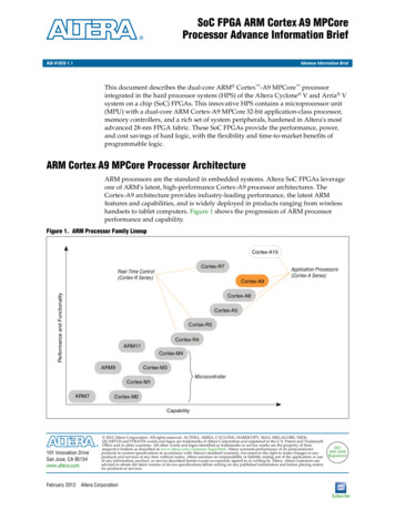
Functional Description2.1About the functionsFigure 2-1 shows the structure of the Cortex-M4 processor.Cortex-M4 processorCortex-M4 pts andpower control‡EmbeddedTraceMacrocell(ETM)‡ Floating PointUnit (FPU)‡Wake-upInterruptController(WIC)‡ Serial-Wireor JTAGDebug Port(SW-DP orSWJ-DP)Serial-Wire orJTAG DebugInterface‡‡Flash PatchBreakpoint(FPB)‡DataWatchpointand Trace(DWT)MemoryProtectionUnit (MPU)‡‡AHBAccess Port(AHB-AP)ICodeAHB-LiteinstructioninterfaceBus eminterface‡InstrumentationTrace Macrocell(ITM)Trace PortInterface Unit(TPIU)Trace PortInterface‡ CoreSightROM tablePPB APBdebug systeminterface‡ Optional componentFigure 2-1 Cortex-M4 block diagramThe Cortex-M4 processor features: ARM DDI 0439DID061113A low gate count processor core, with low latency interrupt processing that has:—A subset of the Thumb instruction set, defined in the ARM v7-M ArchitectureReference Manual.—Banked Stack Pointer (SP).—Hardware integer divide instructions, SDIV and UDIV.—Handler and Thread modes.—Thumb and Debug states.—Support for interruptible-continued instructions LDM, STM, PUSH, and POP for lowinterrupt latency.—Automatic processor state saving and restoration for low latency Interrupt ServiceRoutine (ISR) entry and exit.—Support for ARMv6 big-endian byte-invariant or little-endian accesses.—Support for ARMv6 unaligned accesses.Copyright 2009, 2010, 2013 ARM Limited. All rights reserved.Non-Confidential2-2
Functional Description ARM DDI 0439DID061113Optional Floating Point Unit (FPU) providing:—32-bit instructions for single-precision (C float) data-processing operations.—Combined Multiply and Accumulate instructions for increased precision (FusedMAC).—Hardware support for conversion, addition, subtraction, multiplication withoptional accumulate, division, and square-root.—Hardware support for denormals and all IEEE rounding modes.—32 dedicated 32-bit single precision registers, also addressable as 16 double-wordregisters.—Decoupled three stage pipeline.Nested Vectored Interrupt Controller (NVIC) closely integrated with the processor coreto achieve low latency interrupt processing. Features include:—External interrupts, configurable from 1 to 240.—Bits of priority, configurable from 3 to 8.—Dynamic reprioritization of interrupts.—Priority grouping. This enables selection of preempting interrupt levels and nonpreempting interrupt levels.—Support for tail-chaining and late arrival of interrupts. This enables back-to-backinterrupt processing without the overhead of state saving and restoration betweeninterrupts.—Processor state automatically saved on interrupt entry, and restored on interrupt exit,with no instruction overhead.—Optional Wake-up Interrupt Controller (WIC), providing ultra-low power sleepmode support.Memory Protection Unit (MPU). An optional MPU for memory protection, including:—Eight memory regions.—Sub Region Disable (SRD), enabling efficient use of memory regions.—The ability to enable a background region that implements the default memory mapattributes.Bus interfaces:—Three Advanced High-performance Bus-Lite (AHB-Lite) interfaces: ICode,DCode, and System bus interfaces.—Private Peripheral Bus (PPB) based on Advanced Peripheral Bus (APB) interface.—Bit-band support that includes atomic bit-band write and read operations.—Memory access alignment.—Write buffer for buffering of write data.—Exclusive access transfers for multiprocessor systems.Low-cost debug solution that features:—Debug access to all memory and registers in the system, including access tomemory mapped devices, access to internal core registers when the core is halted,and access to debug control registers even while SYSRESETn is asserted.—Serial Wire Debug Port (SW-DP) or Serial Wire JTAG Debug Port (SWJ-DP) debugaccess.Copyright 2009, 2010, 2013 ARM Limited. All rights reserved.Non-Confidential2-3
Functional DescriptionARM DDI 0439DID061113—Optional Flash Patch and Breakpoint (FPB) unit for implementing breakpoints andcode patches.—Optional Data Watchpoint and Trace (DWT) unit for implementing watchpoints,data tracing, and system profiling.—Optional Instrumentation Trace Macrocell (ITM) for support of printf() styledebugging.—Optional Trace Port Interface Unit (TPIU) for bridging to a Trace Port Analyzer(TPA), including Single Wire Output (SWO) mode.—Optional Embedded Trace Macrocell (ETM) for instruction trace.Copyright 2009, 2010, 2013 ARM Limited. All rights reserved.Non-Confidential2-4
Functional Description2.2InterfacesThe processor contains the following external interfaces: Bus interfaces. ETM interface on page 2-7. AHB Trace Macrocell interface on page 2-7. Debug Port AHB-AP interface on page 2-7.2.2.1Bus interfacesThe processor contains three external Advanced High-performance Bus (AHB)-Lite businterfaces and one Advanced Peripheral Bus (APB) interface: ICode memory interface. DCode memory interface on page 2-6. System interface on page 2-6. Private Peripheral Bus (PPB) on page 2-6.The processor matches the AMBA 3 specification except for maintaining control informationduring waited transfers. The AMBA 3 AHB-Lite Protocol states that when the slave isrequesting wait states the master must not change the transfer type, except for the followingcases: On an IDLE transfer, the master can change the transfer type from IDLE to NONSEQ. On a BUSY transfer with a fixed length burst, the master can change the transfer typefrom BUSY to SEQ. On a BUSY transfer with an undefined length burst, the master can change the transfertype from BUSY to any other transfer type.The processor does not match this definition because it might change the access type from SEQor NONSEQ to IDLE during a waited transfer. The processor might also change the address orother control information and therefore
ARM v7-M Architecture Reference Manual (ARM DDI 0403). ARM Cortex-M4 Integration and Implementation Manual (ARM DII 0239). ARM ETM-M4 Technical Reference Manual (ARM DDI 0440). ARM AMBA 3 AHB-Lite Protocol (v1.0) (ARM IHI 0033). ARM AMBA 3 APB Protocol Specification (ARM IHI 0024).