Transcription
M424Installation GuideVerifone Part Number DOC380-003-EN-A, Revision A
M424 Installation Guide 2020 Verifone, Inc.All rights reserved. No part of the contents of this document may be reproduced or transmitted in any form without the writtenpermission of Verifone, Inc.The information contained in this document is subject to change without notice. Although Verifone has attempted to ensure theaccuracy of the contents of this document, this document may include errors or omissions. The examples and sample programs arefor illustration only and may not be suited for your purpose. You should verify the applicability of any example or sample programbefore placing the software into productive use. This document, including without limitation the examples and software programs, issupplied “As-Is.”Verifone, and the Verifone logo are registered trademarks of Verifone.Other brand names or trademarks associated with Verifone’s products and services are trademarks of Verifone, Inc. All other brandnames and trademarks appearing in this manual are the property of their respective holders.Product WarrantyFor product warranty information, go to http://www.verifone.com/terms.Comments? Please e-mail all comments in this document to your local Verifone Support Team.Verifone, Inc.1-800-Verifonewww.verifone.comVerifone Part Number DOC380-003-EN-A , Revision A
CONTENTSP R EF AC E . . . . . . . . . . . . . . . . . . . . . . . . . . . . . . . . . . . . . . . 5Audience. . . . . . . . . . . . . . . . . . . . . . . . . . . . . . . . . . . . . . . . . . . . . . . . . . . . . . . .Organization . . . . . . . . . . . . . . . . . . . . . . . . . . . . . . . . . . . . . . . . . . . . . . . . . . . . .Related Documentation . . . . . . . . . . . . . . . . . . . . . . . . . . . . . . . . . . . . . . . . . . . .Guide Conventions . . . . . . . . . . . . . . . . . . . . . . . . . . . . . . . . . . . . . . . . . . . . . . . .Acronym Definitions . . . . . . . . . . . . . . . . . . . . . . . . . . . . . . . . . . . . . . . . . . . .55567C HA P TE R 1Device Overview Features and Benefits . . . . . . . . . . . . . . . . . . . . . . . . . . . . . . . . . . . . . . . . . . . . 11Exceptional Ease of Use. . . . . . . . . . . . . . . . . . . . . . . . . . . . . . . . . . . . . . . .Performance and Durability . . . . . . . . . . . . . . . . . . . . . . . . . . . . . . . . . . . . .Security . . . . . . . . . . . . . . . . . . . . . . . . . . . . . . . . . . . . . . . . . . . . . . . . . . . . .Contactless Capability . . . . . . . . . . . . . . . . . . . . . . . . . . . . . . . . . . . . . . . . .Communication Technology . . . . . . . . . . . . . . . . . . . . . . . . . . . . . . . . . . . . .1111111111C HA P TE R 2Setup Device Location . . . . . . . . . . . . . . . . . . . . . . . . . . . . . . . . . . . . . . . . . . . . . . . . . 13Ease of Use . . . . . . . . . . . . . . . . . . . . . . . . . . . . . . . . . . . . . . . . . . . . . . . . .Environmental Factors . . . . . . . . . . . . . . . . . . . . . . . . . . . . . . . . . . . . . . . . .Electrical Considerations . . . . . . . . . . . . . . . . . . . . . . . . . . . . . . . . . . . . . . .PIN Protection Measures . . . . . . . . . . . . . . . . . . . . . . . . . . . . . . . . . . . . . . . . . .Mounting Considerations . . . . . . . . . . . . . . . . . . . . . . . . . . . . . . . . . . . . . . .Inside the Shipping Carton . . . . . . . . . . . . . . . . . . . . . . . . . . . . . . . . . . . . . . . . .Device Features . . . . . . . . . . . . . . . . . . . . . . . . . . . . . . . . . . . . . . . . . . . . . . . . .Front Panel . . . . . . . . . . . . . . . . . . . . . . . . . . . . . . . . . . . . . . . . . . . . . . . . . .Connection Ports . . . . . . . . . . . . . . . . . . . . . . . . . . . . . . . . . . . . . . . . . . . . . . . .Connecting Cables and other Devices . . . . . . . . . . . . . . . . . . . . . . . . . . . . .M424 Connection Options . . . . . . . . . . . . . . . . . . . . . . . . . . . . . . . . . . . . . . . . .Powered Multiport Cable. . . . . . . . . . . . . . . . . . . . . . . . . . . . . . . . . . . . . . . .MSAM Card . . . . . . . . . . . . . . . . . . . . . . . . . . . . . . . . . . . . . . . . . . . . . . . . . . . .Device Power Source . . . . . . . . . . . . . . . . . . . . . . . . . . . . . . . . . . . . . . . . . . . . .Smart Card Reader . . . . . . . . . . . . . . . . . . . . . . . . . . . . . . . . . . . . . . . . . . . . . .Magnetic Card Reader . . . . . . . . . . . . . . . . . . . . . . . . . . . . . . . . . . . . . . . . . . . .Contactless Smart Card Transaction . . . . . . . . . . . . . . . . . . . . . . . . . . . . . . . . .M424 Wi-Fi/BT Support . . . . . . . . . . . . . . . . . . . . . . . . . . . . . . . . . . . . . . . . . . .Bluetooth Support . . . . . . . . . . . . . . . . . . . . . . . . . . . . . . . . . . . . . . . . . . . . .Wireless Transaction . . . . . . . . . . . . . . . . . . . . . . . . . . . . . . . . . . . . . . . . . .Optional Accessories . . . . . . . . . . . . . . . . . . . . . . . . . . . . . . . . . . . . . . . . . . . . .Privacy Shield . . . . . . . . . . . . . . . . . . . . . . . . . . . . . . . . . . . . . . . . . . . . . . . .External and Optional Devices . . . . . . . . . . . . . . . . . . . . . . . . . . . . . . . . . . .Accessories and Documentation . . . . . . . . . . . . . . . . . . . . . . . . . . . . . . . . . . . .Accessories. . . . . . . . . . . . . . . . . . . . . . . . . . . . . . . . . . . . . . . . . . . . . . . . . 5C HA P TE R 3Specifications Power Rating . . . . . . . . . . . . . . . . . . . . . . . . . . . . . . . . . . . . . . . . . . . . . . . . . . . 27Power Pack . . . . . . . . . . . . . . . . . . . . . . . . . . . . . . . . . . . . . . . . . . . . . . . . . . . . 27M424 INSTALLATION GUIDE3
C ONTENTSTemperature . . . . . . . . . . . . . . . . . . . . . . . . . . . . . . . . . . . . . . . . . . . . . . . . . . . .Memory. . . . . . . . . . . . . . . . . . . . . . . . . . . . . . . . . . . . . . . . . . . . . . . . . . . . . . . .Display . . . . . . . . . . . . . . . . . . . . . . . . . . . . . . . . . . . . . . . . . . . . . . . . . . . . . . . .Magnetic Card Reader . . . . . . . . . . . . . . . . . . . . . . . . . . . . . . . . . . . . . . . . . . . .Primary Smart Card . . . . . . . . . . . . . . . . . . . . . . . . . . . . . . . . . . . . . . . . . . . . . .MSAM Card Reader . . . . . . . . . . . . . . . . . . . . . . . . . . . . . . . . . . . . . . . . . . . . . .Integrated Contactless Reader. . . . . . . . . . . . . . . . . . . . . . . . . . . . . . . . . . . . . .Keypad . . . . . . . . . . . . . . . . . . . . . . . . . . . . . . . . . . . . . . . . . . . . . . . . . . . . . . . .Audio Jack . . . . . . . . . . . . . . . . . . . . . . . . . . . . . . . . . . . . . . . . . . . . . . . . . . . . .Peripheral Ports . . . . . . . . . . . . . . . . . . . . . . . . . . . . . . . . . . . . . . . . . . . . . . . . .Security. . . . . . . . . . . . . . . . . . . . . . . . . . . . . . . . . . . . . . . . . . . . . . . . . . . . . . . .2727272727272727282828C H AP T ER 4Maintenance and General Care . . . . . . . . . . . . . . . . . . . . . . . . . . . . . . . . . . . . . . . . . . . . . . . . . . . 29Cleaning Additional Safety Information . . . . . . . . . . . . . . . . . . . . . . . . . . . . . . . . . . . . . . . 30Surface Cleaning . . . . . . . . . . . . . . . . . . . . . . . . . . . . . . . . . . . . . . . . . . . . .Smart Card Reader Cleaning . . . . . . . . . . . . . . . . . . . . . . . . . . . . . . . . . . . .Magnetic Stripe Cleaning . . . . . . . . . . . . . . . . . . . . . . . . . . . . . . . . . . . . . . .Using the Battery . . . . . . . . . . . . . . . . . . . . . . . . . . . . . . . . . . . . . . . . . . . . .30303131C H AP T ER 5Service and Support Service Returns . . . . . . . . . . . . . . . . . . . . . . . . . . . . . . . . . . . . . . . . . . . . . . . . . 33C H AP T ER 6Troubleshooting Device Does Not Start . . . . . . . . . . . . . . . . . . . . . . . . . . . . . . . . . . . . . . . . . . . . 35Guidelines Device Display Does Not Show Correct/Readable Info . . . . . . . . . . . . . . . . . . . 35Blank Display . . . . . . . . . . . . . . . . . . . . . . . . . . . . . . . . . . . . . . . . . . . . . . . . . . . 36Keypad Does Not Respond . . . . . . . . . . . . . . . . . . . . . . . . . . . . . . . . . . . . . . . . 36Transactions Fail to Process . . . . . . . . . . . . . . . . . . . . . . . . . . . . . . . . . . . . . . . 364M424 INSTALLATION GUIDE
PREFACEThis guide is the primary source of information for setting up and installing theVerifone M424 device.AudienceOrganizationThis guide is useful to anyone installing and configuring the M424 device.This guide is organized as follows:Chapter 1, Device Overview. Provides an overview of the Verifone M424 device.Chapter 2, Setup. Explains setup and installation of the device, selecting alocation, and establishing connections with other devices.Chapter 3, Specifications. Discusses power requirements and dimensions of thedevice.Chapter 4, Maintenance and Cleaning. Explains maintenance of the device.Chapter 5, Service and Support. Provides information on contacting your Verifoneservice provider and information on how to order accessories or documentationsfrom Verifone.Chapter 6, Troubleshooting Guidelines. Provides troubleshooting guidelinesshould you encounter a problem in device installation and configuration.RelatedDocumentationM424 INSTALLATION GUIDERefer to the following set of documents to learn more about the device:M424 Certifications and RegulationsVPN - DOC380-001-ENM424 Series Quick Installation GuideVPN - DOC380-002-ENM4xx Accessory Certifications and RegulationsVPN - DOC445-005-ENM4 POE Dongle Certifications and RegulationsVPN - DOC000-001-ENM4xx ESU Dongle Certifications and RegulationsVPN - DOC445-011-EN5
P REFACEGuide ConventionsGuideConventionsVarious conventions are used to help you quickly identify special formatting.Table 1 describes these conventions and provides examples of their use.Table 1ConventionMeaningExampleBlueText in blue indicates terms thatare cross references.See Guide Conventions.ItalicsItalic typeface indicates booktitles or emphasis.You must not use this unitunderwater.The pencil icon is used tohighlight important information.RS232-type devices do not workon the M424 communicationport.CAUTIONThe caution symbol indicateshardware or software failure, orloss of data.The unit is not waterproof ordustproof and is intended forindoor use only.WARNINGThe lightning symbol is used as awarning when bodily injury mightoccur.Do not use the device near waterdue to risk of shock.NOTE6M424 INSTALLATION GUIDEDocument Conventions
P REFACEGuide ConventionsAcronym Definitions Acronyms are used in place of the full definition. Table 2 presents acronyms andtheir definitions.Table 2Acronym DefinitionsAcronymDefinitionsAESAdvanced Encryption Standard AlgorithmARMAdvanced RISC MachineCTLSContactless ReaderDUKPTDerived Unique Key Per Transaction Method as defined in theVISA’s POS Equipment Requirement: PIN processing and DataAuthentication, International Version 1.0, August 1988ECRElectronic Cash RegisterEMVEuropay, MasterCard and Visa StandardMSAMMultiple Secure Access ModuleMSRMagnetic Swipe ReaderNFCNear Field CommunicationPINPersonal Identification NumberPOSPoint-of-SaleQR CodeQuick Response CodeSAMSecure Access ModuleSCRSmart Card ReaderSREDSecure Reading and Exchange of DataUSBUniversal Serial BusWi-FiWireless FidelityM424 INSTALLATION GUIDE7
P REFACEGuide Conventions8M424 INSTALLATION GUIDE
CHAPTER 1Device OverviewThis chapter provides a brief description of the Verifone M424 device.The Verifone M424 device is a best-in-class, single-screen media-capable andconsumer-facing device, which allows electronic payment transactions to beprocessed in multi-lane scenarios. This payment processing solution with a fullyintegrated POS can scan barcodes, QR codes and products with the help ofintegrated camera.In combination with Verifone Connect digital services, it offers self-check-out/selfcheck-in, payment, and the ability to run Android applications, like loyalty andinventory. It also enables clients to remotely monitor and update their device usingVerifone’s estate management solution. The Verifone M424 device supportsBluetooth and Wi-Fi. It meets PCI-PTS 5.X SRED requirements for maximumsecurity.The Verifone M424 device supports all payment methods - magnetic stripe, EMV,and NFC/Contactless Reader, including Apple Pay, Google Pay, and SamsungPay mobile wallets. The easy to read color touch screen supports all paymentrelated user interactions and keypad for secure PIN entry.Figure 1M424 DeviceM424 INSTALLATION GUIDE9
D EVICE O VERVIEWKey Features and BenefitsM424 FeaturesProcessor 1.1 GHz, Arm Cortex-A7 quad-core Dedicated secure processorMemory 2 GB RAM 16 GB Flash Secure processor: 512 MB DRAM, 512 MB FlashDisplay 5.5-inch (120.77 X 67.93) HD IPS LCD, Capacitive TouchscreenKeypad (touch) Dedicated mechanical keypad and on-screen (touch)keypad.Payment Magnetic Swipe Reader (MSR) Smart Card Reader (SCR) Contactless Reader (CTLS) Near Field Communication (NFC) Quick Response (QR) codeCommunication Bluetooth 4.2 BLE 2.4 GHz 5 GHz Wi-Fi, 802.11 a, b, g, nPeripheral Ports Custom Multiport InterfaceCamera 5 MP (front QR/Barcode Scanner) Auto-focus Fast scannerSecurity PCI PTS 5.x-approved SRED Supports AES DUKPTSIM/SAM 2 Standard SAMEnvironmental Operating temperature: 0 to 40 C (32 to 104 F) Storage temperature: -20 to 60 C (-4 to 140 F) Relative humidity: 5% to 95% Non-condensing10M424 INSTALLATION GUIDE
D EVICE O VERVIEWFeatures and BenefitsFeatures andBenefitsFollowing are the features and benefits.Exceptional Ease of UseLarge 5.5” LCD display for unlimited application possibilities and easyreadability under various lighting conditions. Touchscreen for icon-based applications or electronic signature capturesupport. Intuitive telco-style keypad with colored control keys. Bi-directional magnetic stripe card reader with an extended blade for optimalcard reading. Audio jack to facilitate accessibility for the visually impaired.Performance and DurabilityFast transactions due to powerful 1 GHz ARM Cortex and quad-core ARMCortex-A7 1.1GHz processor. Rounded corners and drop resistant to less than 75cm on concrete floor tominimize breakage. 16GB of Flash memory and 2GB SDRAM.Security Incorporates tamper-sensing circuitry to detect unauthorized intrusion andsupports a broad spectrum of software-based security features. PCI-PTS 5.x approved for debit and other PIN-based transactions. EMV Level 1 Type Approval. Supports reliable security features including TLS, VeriShield fileauthentication, and VeriShield Protect to help prevent fraud and otherintrusions.Contactless CapabilityAdvanced contactless architecture that future-proofs investment with a singlecontactless interface (SingleCl), SoftSAMs, and side-by-side applicationarchitecture. Dedicated tap zone for optimized user experience. Accepts EMV, NFC, QR Code and mag-stripe contactless payments as well asPIN-based transactions.Communication TechnologyBluetooth: Simple, plug-and-play installation for locations that need shortrange wireless capability. Eddystone and iBeacon profiles are also supported. Wi-Fi: Ideal for retailers that need multiple wireless devices and have anexisting IP infrastructure.M424 INSTALLATION GUIDE11
D EVICE O VERVIEWFeatures and Benefits12M424 INSTALLATION GUIDE
CHAPTER 2SetupThis chapter describes the setup procedure for:Device Location Device Location. Inside the Shipping Carton. Device Features. Connection Ports. M424 Connection Options. MSAM Card. Device Power Source. Smart Card Reader. Magnetic Card Reader. Contactless Smart Card Transaction. M424 Wi-Fi/BT Support. Optional Accessories.The following are guidelines used to select an ideal location for the device. Ease of Use NOTEThe device must be used in an attended environment.Select a location convenient for both merchant and cardholder. Select a flat support surface less than two meters high, such as a countertopor table, or secure the device on a stand mount supplied by Verifone. Select a location near a power outlet, POS, ECR, or computer connected tothe device. For safety, do not string cables or cords across a walkway. The M424 device must be mounted only on Verifone approved stands. The device is suitable for mounting only at height less than or equal to 2meters.Environmental FactorsDo not use the device where there is excess heat, dust, humidity, moisture,caustic chemicals or oils. Keep the device away from direct sunlight and anything that radiates heat,such as a stove or a motor. Do not use the device outdoors.M424 INSTALLATION GUIDE13
S ETUPPIN Protection MeasuresElectrical Considerations Avoid using this product during electrical storms.Avoid locations near electrical appliances or other devices that causeexcessive voltage fluctuations or emit electrical noise (for example, airconditioners, electric motors, neon signs, high-frequency or magnetic securitydevices, or computer equipment). Avoid using the device near water or in moist conditions. Disconnect the device from its POS device before cleaning.WARNING Do not use the device near water, including a bathtub, wash bowl, kitchen sink orlaundry tub, in a wet basement, or near a swimming pool to avoid shock ordamage.PIN ProtectionMeasuresUse the following techniques to provide effective screening of the PIN-entrykeypad during the PIN entry process. You can use these methods in combination,although in some cases a single method might suffice. Position the device on the check-in stand in such a way as to block visualobservation of the PIN-entry process. Examples include: Visual shields designed into the check-in stand. The shields may be solelyfor shielding purposes or may be part of the general check-in stand design. Position the device so that it is angled in such a way that PIN spying isdifficult. Install the PED on an adjustable stand that allows consumers to swivel thedevice sideways and/or tilt it forwards/backwards to a position that makesvisual observation of the PIN-entry process difficult. Position in-store security cameras so that the PIN-entry keypad is not visible. This risk of shoulder-spying during PIN entry can be significantly reduced byinstalling the optional approved privacy shield.The following table describes the two preferred mounting methods and therecommended measures to protect against PIN capture in four observationcorridors:Table 314M424 INSTALLATION GUIDEMounting Methods and Protection MeasuresCustomer inQueueCustomersElsewhereOn-siteCamerasUse signagebehind thePEDInstall so thatcustomer isbetween PED andnext in queueNo actionneededDo not installwithin view ofcamerasNo actionneededInstall so thatcustomer isbetween PED andnext in queueNo actionneededDo not installwithin view ofcamerasMethodCashierCountertopwithout standCountertopwith stand
S ETUPInside the Shipping CartonVerifone also recommends instructing the cardholder regarding safe PIN-entry.This can be done with a combination of: Signage on the PED Prompts on the display, possibly with a click-through screen Literature at the point of sale A logo for safe PIN-entry process. You can secure PIN entry by installing a Privacy Shield (optional).Mounting Verifone recommends the use of an approved stand for all mounting situations.Considerations Position the device conveniently in relation to power, POS, ECR, and LANconnections. Ensure the M424 device is placed in a manner that allows customersto swipe their magnetic cards or insert their Smart Cards in a smooth andcomfortable motion without encountering obstructions. If the unit needs to beswiveled during normal operation, Verifone recommends the use of an approvedswivel stand.NOTEInside theShipping CartonSpecial care is required while mounting the M424 device in sites that utilize antitheft devices positioned at doorways or surface mounted deactivator pads.Devices of this type, such as Sensormatic brand devices generate strongelectromagnetic fields, which may interfere with M424 device. Always selectmounting locations at least 0.5 meter from doorway units and at least 2.0 metersfrom surface mounted deactivator pads.Open the shipping carton and carefully inspect its contents for possible tamperingor shipping damage. The device is a secure product. Tampering causes it tocease to function or to operate in an unsecured manner.Unpacking the To unpack the shipping carton:Shipping Carton1 Carefully inspect the shipping carton and its contents for possible tampering ordamage.2 Validate the authenticity of the sender by verifying the shipping trackingnumber and other information located on the product order paperwork.3 Remove and inspect the contents of the shipping carton. The device ships inmultiple configurations, the carton may include all or any of the following:NOTE Device Connectivity cable Additional accessoriesPower supply and connectivity cables are shipped separately or depending onthe customer requirements.M424 INSTALLATION GUIDE15
S ETUPInside the Shipping Carton4 Remove all plastic wrapping from the device and components.5 Remove the clear protective film from the display.6 Inspect the terminal for possible tampering; see how to identify signs oftampering in section Periodic Inspection.7 Save the shipping carton and packing material for future repacking or movingof the device.WARNING Do not use a tampered or damaged unit. The device comes equipped withtamper-evident labels. If a label or component appears damaged, please notifythe shipping company and your Verifone service provider immediately.NE6ERIFO6ERIFONEPeriodic Inspection Periodically inspect the terminal for possible tampering. Signs of tamperinginclude: Overlays in the PIN pad area Wires protruding out of the device Foreign objects inserted into the smart card slot or magnetic stripe slot Any bumps in the casing below the mag stripe slot and any noticeableadditional mag stripe head from the side Signs of damage to the tamper-evident labels A Tamper Warning message on the device displayIf any device is found to have been tampered with, please remove it from serviceimmediately, keep it available for potential forensics investigation, and notify yourcompany security officer and your local Verifone representative or serviceprovider. To contact Verifone, please see Service and Support.For terminals equipped with a privacy shield, perform daily inspections to ensurethat the privacy shield is installed and has not been removed.16M424 INSTALLATION GUIDE
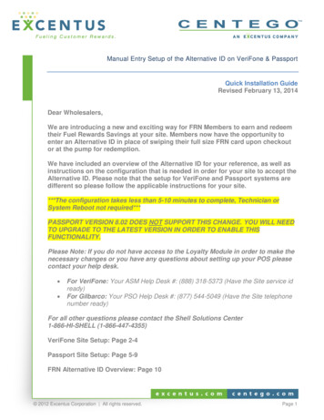
S ETUPDevice FeaturesDevice FeaturesFamiliarize yourself with the device features before continuing with the installationprocess:4/5#( 3#2%%. )30,!9#4,3 0!9-%.4:/.% ,% 3 4/ ). )#!4%#!2 37)0% 2%! 9!5 )/ *!# -!'.%4)# #!2 2%! %23-!24 #!2 2%! %2#!-%2! 3#!.%24%,#/ 349,% %90! Figure 2M424 FeaturesFront Panel The front panel offers the following features: The Verifone M424 device has a colored touch screen Display. A smart card reader built into the front of the device to process smart cardbased debit or credit transactions. For directions on how to use a smart card,see Using the Smart Card Reader. A magnetic card reader built into the device for performing debit or credit cardtransactions. The card can be swiped from either direction. To ensure a properread of the magnetic swipe card, insert the magnetic card from the side of thedevice as shown in Figure 11. Contactless Reader and EMV have dedicated LEDs lower to the left of thedisplay for contactless payments. For directions on how to conduct contactlesstransactions, see Using the Contactless Reader. 4 white LEDs support CTLS transaction function. 3 white LEDs support MSR transaction function. 1 white LED to support EMV (CHIP) transaction function.A 3.5 mm audio jack to facilitate accessibility for the visually impaired.NOTEOn screen PIN entry is NOT supported.M424 INSTALLATION GUIDE17
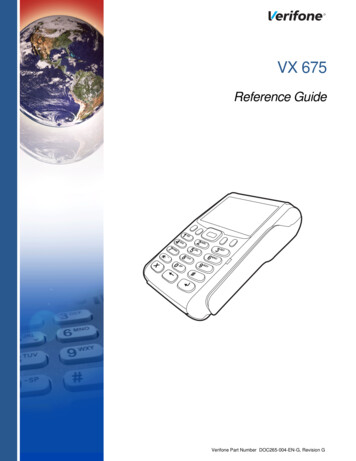
S ETUPConnection PortsConnectionPortsThe device has one custom multiport interface for power and communicationsconnection.Connecting Cables To connect required cable connections and other devices:and other Devices1 Unscrew and remove cable cover as shown below.Figure 3Removing Cable Cover2 Connect required cable connections or optional devices. Attaching themultiport cable provides multiple connection options.3!- 3!- 3!- 3!- Figure 4Multiport Cable Connected on the Rear of the UnitNOTERoute the multiport cable through the cable cover first, as shown in the picture.18M424 INSTALLATION GUIDE
S ETUPConnection Ports3 Close cable compartment as shown below.Figure 5Closing Cable Compartment with Cable CoverM424 INSTALLATION GUIDE19
S ETUPM424 Connection OptionsM424ConnectionOptionsThe M424 device can be connected to other systems using several methods.They all connect to the M424 using the Multiport cable connected on the rear ofthe unit.Powered Multiport Powered Multiport Cable provides USB signal connectivity and power. It providesCable a convenient way of connecting other systems of the same type.Figure 6MSAM CardPowered Multiport CableYou may need to install one or two Multiple Security Access Module (MSAM)cards or replace an old one.CAUTION Observe standard precautions in handling electrostatically sensitive devices.Electrostatic discharge can damage the equipment. Verifone recommends usinga grounded anti-static wrist strap.Installing or To install or replace MSAM cards:Replacing MSAMCard 1 Power off the device.2 Place the device face down on a soft and clean surface.3 Remove the cable cover of the unit.4 Insert the MSAM cards. Carefully slide the cards one at a time into the slotsuntil fully inserted. The correct orientation of the MSAM card is as indicated inthe figure 7.5 Close the cable cover.20M424 INSTALLATION GUIDE
S ETUPDevice Power Source3!- 3!- 213!- 3!- Figure 7NOTEMSAM InsertionPosition the card’s gold contacts facing downward toward the user. The card slotin the device has a set of contacts. The MSAM card has a notch on one corner toensure that it fits into the connector base in only one way.To replace SAM card, gently slide out the old SAM card before inserting a newone.Device PowerSourceThe device is powered by an external AC/DC power pack. When you havefinished installing the necessary cards and/or optional devices, you are ready toconnect the device to the power source.The device requires connection to a power outlet with a dedicated circuit or anuninterruptible power supply (UPS). If other devices are plugged into the samecircuit, the device can potentially experience power fluctuations that might causemalfunction. The device shuts down automatically once power source is removed.WARNING Do not connect the device to the power supply until all peripherals are attached.Using an incorrectly rated power supply can damage the unit or cause it not towork properly. See Specifications for detailed power supply specifications.Do not plug the power pack into an outdoor outlet or operate the device outdoors.Disconnecting power during a transaction can also cause unsaved data files tobe lost.NOTEVerifone recommends installing a power surge protector to protect againstpossible damage caused by lightning strikes and electrical surges.Connecting M424 To connect M424 device to a power source:Device to a PowerSource 1 Connect the Multiport cable (Example MSC445-010-00-A) to the Multiport atthe back of the device.M424 INSTALLATION GUIDE21
S ETUPSmart Card Reader2 Close cable cover.3!- 3!- 3!- 3!- Figure 8Connecting Base Cable to Device3 Plug in power supply to the power connection port on the base module.4 Plug the AC power cord into a wall outlet or power surge protector.Smart CardReaderThe smart card transaction procedure can vary depending on the application.Verify the proper procedure with your application provider before performing asmart card transaction.Using the Smart Card To use the smart card reader:Reader1 Position the smart card with the gold contacts facing upward.2 Insert the card into the smart card reader slot in a smooth, continuous motionuntil it sets firmly.Figure 9Smart Card Reader3 Remove the card only when the display indicates the transaction is complete.CAUTIONMagnetic CardReader22M424 INSTALLATION GUIDELeave the smart card in the card reader until the transaction is completed.Premature card removal can invalidate a transaction.The device has a magnetic card reader that uses a triple track stripe reader. Thisgives the unit greater reliability over a wide range of swipe speeds and operatingenvironments.
S ETUPContactless Smart Card TransactionUsing the To use the MSR (credit/debit card transaction):MSR(Credit/DebitCard Transaction) 1 MSR indicator lights will flash when ready to accept MSR transaction.2 Position a magnetic card with the stripe to face downward, as shown in Figure10.3 Swipe the card through the magnetic card reader.Figure 10ContactlessSmart CardTransactionUsing the Magnetic Card ReaderThe device supports contactless transactions through an integrated contactlessmodule. The device only becomes active for contactless smart card transactionswhen initialized by an application.Performing a To perform a contactless smart card transaction:Contactless SmartCard Transaction 1 Gently tap the card onto payment device or hold the card within 4 cm againstthe surface of the device on the left side of keypad above the ContactlessReader icon.2 Activated LED icons accompanied by a short beeping sound indicates asuccessful transaction.Figure 11CAUTIONM424 Wi-Fi/BTSupportContactless Smart Card TransactionDo not allow metallic surfaces to come in contact with the contactless module toensure that it works properly.The M424 device includes an integrated WLAN RF transceiver for Wireless LANsystems with advanced power management,
Bi-directional magnetic stripe card reader with an extended blade for optimal card reading. Audio jack to facilitate accessibility for the visually impaired. Performance and Durability Fast transactions due to powerful 1 GHz ARM Cortex and quad-core ARM Cortex-A7 1.1GHz processor.