Transcription
High-Performance Delta-Sigma Analog-to-Digital ConvertersbyJosé Barreiro da SilvaA THESISsubmitted toOregon State Universityin partial fulfillment ofthe requirements for thedegree ofDoctor of PhilosophyPresented July 14, 2004Commencement June 2005
ACKNOWLEDGMENTSI wish to express my deepest gratitude to my research advisors, Dr. Gábor Temesand Dr. Un-Ku Moon, who provided me with an excellent research environment. I feelgreatly honored to have worked under the guidance of Dr. Temes. I benefited fromhis extensive knowledge in circuit design, invaluable teaching and research skills, andsupport in technical and personal matters. I thank him for his kindness, friendship,and for being a source of inspiration at every level. It was also a great honor to havebeen advised by Dr. Moon. I learned many fundamental circuit design skills from him.I appreciated his enthusiastic, always honest feedback. I thank him for his valuableguidance and encouragement throughout my research.I would like to thank Prof. Karti Mayaram, Prof. Huaping Liu, Dr. Adrian Earlyand Prof. Bruce D’Ambrosio for serving in my graduate committee.I am grateful to my close friends Matt Brown, Pavan Hanumolu, José Ceballosand Gilcho Ahn, for many fruitful and good-humored discussions, for their help withtechnical and non-technical matters, and for countless pleasant memories from our timetogether. In particular, I thank Pavan for helping me to keep things in perspective, andJosé Ceballos for his delightful cheerfulness. I have a special appreciation for Matt, forhis genuine concern for my personal well-being, and for his kind help during difficulttimes.I also wish to acknowledge all my officemates, who contributed in many waysto an outstanding environment: in no particular order, I would like to acknowledgeXuesheng Wang, Mingyu Kim, Merrick Brownlee, Vova, Charlie Myers, Kerem Ok,Shelly Xiao, Anurag Pulincherry, Jipeng Li, Mustafa Keskin, Dong-Young Chang, KyeHyung Lee, Younjae Kook, Byung-Moo Min, Ranganathan Desikachari, Kiseok Yoo,Zhenyong Zhang, Ting Wu, Dan Thomas, Brandon Greenley and Jacob Zechmann.I was fortunate to spend my first years at OSU with Tetsuya Kajita, with whomI shared many classes and group projects. I’m grateful for the wonderful times that we
spent together and with his family. I have high esteem for János Márkus and JohannaMárkus for many memorable experiences shared together. I wish to thank MutsukoKajita, Melinda Valencia and Marcela Andolina, for their help, friendship and for manyenjoyable moments outside the research environment. I am grateful to Ibi Temes for herkindness, and for many delightful visits to the Temes’ home.My teaching assistantships at OSU were significant in the development of myknowledge of circuits and systems. For that, I wish to acknowledge all the students whohelped by asking hard questions.For their important contributions to this work, I wish to thank Dr. XueshengWang, Robert Batten, Dr. Péter Kiss, Dr. Jesper Steensgaard and Dr. Anas Hamoui. Iam indebted to Paul Ferguson, Richard Schreier, Steve Lewis, and many other people atAnalog Devices, for their help with design reviews, and for their invaluable feedback onmany circuit design and testing issues. I’m thankful to Jonathan Schweitzer of LucentTechnologies for fabricating the first prototype. I would also like to thank Bill McIntyre,Keith Schoendoerfer, Arun Rao and Mengzhe Ma, at National Semiconductor Corporation, for their help with the fabrication of the second prototype chips. I appreciateGeorge Corrigan, Terry McMahon and Keith Moore, at Hewlett Packard, for their assistance with FIB modifications. This work would not have been possible without thegenerous financial support provided by the NSF Center for the Design of Analog andDigital Integrated Circuits (CDADIC).I wish to thank the ECE office staff for their top-quality support, and for alwaysletting me know when there were cookies in the office: Sarah O’Leary, Ferne Simendinger,Morgan Garrison, Clara Knutson, Brian Lindsey, Nancy Brown, Cory Williams and TinaBatten. I’m also grateful to Chris Tasker and Manfred Dittrich for their help with mytest setup preparations.Finally, words cannot adequately express my deepest gratitude to my sister and tomy deceased parents, who demonstrated in so many admirable ways their unconditionallove and support throughout my life.
TABLE OF CONTENTSPage1. INTRODUCTION . . . . . . . . . . . . . . . . . . . . . . . . . . . . . . . . . . . . . . . . . . . . . . . . . . . . . . . . .11.1.Motivation . . . . . . . . . . . . . . . . . . . . . . . . . . . . . . . . . . . . . . . . . . . . . . . . . . . . . . . . . . . .11.2.Contributions . . . . . . . . . . . . . . . . . . . . . . . . . . . . . . . . . . . . . . . . . . . . . . . . . . . . . . . . .31.3.Thesis Organization . . . . . . . . . . . . . . . . . . . . . . . . . . . . . . . . . . . . . . . . . . . . . . . . . . .42. DELTA-SIGMA BASICS . . . . . . . . . . . . . . . . . . . . . . . . . . . . . . . . . . . . . . . . . . . . . . . . . . .62.1.Nyquist-Rate vs Oversampling Converters . . . . . . . . . . . . . . . . . . . . . . . . . . . . .62.2.Data Converter Performance Metrics . . . . . . . . . . . . . . . . . . . . . . . . . . . . . . . . . .92.3.Quantization Noise Analysis. . . . . . . . . . . . . . . . . . . . . . . . . . . . . . . . . . . . . . . . . . . 102.4.Oversampling . . . . . . . . . . . . . . . . . . . . . . . . . . . . . . . . . . . . . . . . . . . . . . . . . . . . . . . . . 132.5.First-Order Noise Shaping. . . . . . . . . . . . . . . . . . . . . . . . . . . . . . . . . . . . . . . . . . . . . 152.5.1. Circuit Implementation . . . . . . . . . . . . . . . . . . . . . . . . . . . . . . . . . . . . . . . . 182.5.2. Simulations . . . . . . . . . . . . . . . . . . . . . . . . . . . . . . . . . . . . . . . . . . . . . . . . . . . . 202.6.Second-Order Noise Shaping . . . . . . . . . . . . . . . . . . . . . . . . . . . . . . . . . . . . . . . . . . 202.7.Generalization . . . . . . . . . . . . . . . . . . . . . . . . . . . . . . . . . . . . . . . . . . . . . . . . . . . . . . . . 222.8.Nonideal Effects. . . . . . . . . . . . . . . . . . . . . . . . . . . . . . . . . . . . . . . . . . . . . . . . . . . . . . . 242.8.1. Tones and Limit Cycles . . . . . . . . . . . . . . . . . . . . . . . . . . . . . . . . . . . . . . . . 252.8.2. Finite Opamp Gain and Coefficient Errors . . . . . . . . . . . . . . . . . . . . . . 262.8.3. Stability . . . . . . . . . . . . . . . . . . . . . . . . . . . . . . . . . . . . . . . . . . . . . . . . . . . . . . . 272.9.Multi-Stage Noise Shaping . . . . . . . . . . . . . . . . . . . . . . . . . . . . . . . . . . . . . . . . . . . . 292.9.1. Theory of Operation . . . . . . . . . . . . . . . . . . . . . . . . . . . . . . . . . . . . . . . . . . . 302.10. Advanced Topics . . . . . . . . . . . . . . . . . . . . . . . . . . . . . . . . . . . . . . . . . . . . . . . . . . . . . . 323. PROBLEMS IN WIDEBAND MASH ADCS . . . . . . . . . . . . . . . . . . . . . . . . . . . . . . . 343.1.Distortion . . . . . . . . . . . . . . . . . . . . . . . . . . . . . . . . . . . . . . . . . . . . . . . . . . . . . . . . . . . . . 343.2.Matching of Analog and Digital NTFs . . . . . . . . . . . . . . . . . . . . . . . . . . . . . . . . . 363.3.Nonlinearities in multibit DACs . . . . . . . . . . . . . . . . . . . . . . . . . . . . . . . . . . . . . . . 38
TABLE OF CONTENTS (Continued)Page3.4.Traditional Solutions (State of the Art) . . . . . . . . . . . . . . . . . . . . . . . . . . . . . . . 424. PROPOSED SOLUTIONS . . . . . . . . . . . . . . . . . . . . . . . . . . . . . . . . . . . . . . . . . . . . . . . . . 454.1.Low-Distortion Delta-Sigma Topologies. . . . . . . . . . . . . . . . . . . . . . . . . . . . . . . . 454.1.1.4.1.2.4.1.3.4.1.4.4.2.47494949Adaptive Compensation of Analog Imperfections . . . . . . . . . . . . . . . . . . . . . . 504.2.1.4.2.2.4.2.3.4.2.4.4.3.Lower Area and Power Consumption in Multibit ImplementationsImproved Input Signal Range . . . . . . . . . . . . . . . . . . . . . . . . . . . . . . . . . .Only one DAC Needed in the Feedback Path . . . . . . . . . . . . . . . . . . .Simplified MASH Architecture . . . . . . . . . . . . . . . . . . . . . . . . . . . . . . . . .Adaptive Noise Cancellation Basics . . . . . . . . . . . . . . . . . . . . . . . . . . . .Adaptive Compensation of Quantization Noise Leakage . . . . . . . . .Adaptive Algorithms . . . . . . . . . . . . . . . . . . . . . . . . . . . . . . . . . . . . . . . . . . .Quantization Noise Leakage Compensation in Low-Distortion Σ Topologies . . . . . . . . . . . . . . . . . . . . . . . . . . . . . . . . . . . . . . . . . . . . . . . . .52535456Digital Estimation and Correction of DAC Errors . . . . . . . . . . . . . . . . . . . . . 585. A HIGH-PERFORMANCE DELTA-SIGMA ADC . . . . . . . . . . . . . . . . . . . . . . . . . . 635.1.MASH 2-2-2 Architecture . . . . . . . . . . . . . . . . . . . . . . . . . . . . . . . . . . . . . . . . . . . . . 635.1.1. Theoretical Performance . . . . . . . . . . . . . . . . . . . . . . . . . . . . . . . . . . . . . . . 655.2.System-Level Simplifications . . . . . . . . . . . . . . . . . . . . . . . . . . . . . . . . . . . . . . . . . . 665.2.1. Adaptive Filter Coefficients . . . . . . . . . . . . . . . . . . . . . . . . . . . . . . . . . . . . 685.2.2. System Level Simulations . . . . . . . . . . . . . . . . . . . . . . . . . . . . . . . . . . . . . . 696. NOISE AND LINEARITY REQUIREMENTS . . . . . . . . . . . . . . . . . . . . . . . . . . . . . 726.1.Noise Analysis . . . . . . . . . . . . . . . . . . . . . . . . . . . . . . . . . . . . . . . . . . . . . . . . . . . . . . . . 726.2.Noise Sources . . . . . . . . . . . . . . . . . . . . . . . . . . . . . . . . . . . . . . . . . . . . . . . . . . . . . . . . . 736.2.1. kT/C Noise . . . . . . . . . . . . . . . . . . . . . . . . . . . . . . . . . . . . . . . . . . . . . . . . . . . . 746.2.2. Opamp Noise . . . . . . . . . . . . . . . . . . . . . . . . . . . . . . . . . . . . . . . . . . . . . . . . . . 75
TABLE OF CONTENTS (Continued)Page6.3.Effect of Thermal Noise on the MASH ADC Performance . . . . . . . . . . . . . 776.3.1. Capacitor Sizing . . . . . . . . . . . . . . . . . . . . . . . . . . . . . . . . . . . . . . . . . . . . . . . 786.4.Quantizer Linearity . . . . . . . . . . . . . . . . . . . . . . . . . . . . . . . . . . . . . . . . . . . . . . . . . . . 796.5.DAC Linearity . . . . . . . . . . . . . . . . . . . . . . . . . . . . . . . . . . . . . . . . . . . . . . . . . . . . . . . . 816.6.Digital Truncation Noise . . . . . . . . . . . . . . . . . . . . . . . . . . . . . . . . . . . . . . . . . . . . . . 826.7.Noise Summary . . . . . . . . . . . . . . . . . . . . . . . . . . . . . . . . . . . . . . . . . . . . . . . . . . . . . . . 827. PROTOTYPE CHIP DESIGN — ANALOG SECTION . . . . . . . . . . . . . . . . . . . . 847.1.Modulator Stages . . . . . . . . . . . . . . . . . . . . . . . . . . . . . . . . . . . . . . . . . . . . . . . . . . . . . 847.2.Switch Design . . . . . . . . . . . . . . . . . . . . . . . . . . . . . . . . . . . . . . . . . . . . . . . . . . . . . . . . . 857.2.1. Switch Types and Sizes . . . . . . . . . . . . . . . . . . . . . . . . . . . . . . . . . . . . . . . . 857.2.2. Bootstrapped Switches . . . . . . . . . . . . . . . . . . . . . . . . . . . . . . . . . . . . . . . . . 897.3.Opamp Design . . . . . . . . . . . . . . . . . . . . . . . . . . . . . . . . . . . . . . . . . . . . . . . . . . . . . . . . 917.3.1. Opamp Requirements . . . . . . . . . . . . . . . . . . . . . . . . . . . . . . . . . . . . . . . . . . 927.3.2. Loop-Gain Specifications . . . . . . . . . . . . . . . . . . . . . . . . . . . . . . . . . . . . . . . 957.3.3. Opamp Problems . . . . . . . . . . . . . . . . . . . . . . . . . . . . . . . . . . . . . . . . . . . . . . 967.4.Quantizers . . . . . . . . . . . . . . . . . . . . . . . . . . . . . . . . . . . . . . . . . . . . . . . . . . . . . . . . . . . . 987.4.1. Effects of Passive Adder on Quantizer . . . . . . . . . . . . . . . . . . . . . . . . . . 997.4.2. Comparator Design . . . . . . . . . . . . . . . . . . . . . . . . . . . . . . . . . . . . . . . . . . . . 1018. PROTOTYPE CHIP DESIGN — DIGITAL SECTION . . . . . . . . . . . . . . . . . . . . 1058.1.Encoders . . . . . . . . . . . . . . . . . . . . . . . . . . . . . . . . . . . . . . . . . . . . . . . . . . . . . . . . . . . . . . 1058.2.Scrambler . . . . . . . . . . . . . . . . . . . . . . . . . . . . . . . . . . . . . . . . . . . . . . . . . . . . . . . . . . . . . 1078.2.1. Scrambler Delay . . . . . . . . . . . . . . . . . . . . . . . . . . . . . . . . . . . . . . . . . . . . . . . 1088.3.Noise Cancellation Logic . . . . . . . . . . . . . . . . . . . . . . . . . . . . . . . . . . . . . . . . . . . . . . 1108.3.1. FIR and Correlation Blocks . . . . . . . . . . . . . . . . . . . . . . . . . . . . . . . . . . . . 1108.3.2. FIR Coefficients . . . . . . . . . . . . . . . . . . . . . . . . . . . . . . . . . . . . . . . . . . . . . . . 1138.3.3. Multipliers . . . . . . . . . . . . . . . . . . . . . . . . . . . . . . . . . . . . . . . . . . . . . . . . . . . . . 114
TABLE OF CONTENTS (Continued)Page8.3.4. Correlators . . . . . . . . . . . . . . . . . . . . . . . . . . . . . . . . . . . . . . . . . . . . . . . . . . . . 1158.3.5. Synchronization . . . . . . . . . . . . . . . . . . . . . . . . . . . . . . . . . . . . . . . . . . . . . . . . 1158.4.Additions/Scaling . . . . . . . . . . . . . . . . . . . . . . . . . . . . . . . . . . . . . . . . . . . . . . . . . . . . . 1168.5.Clock generator . . . . . . . . . . . . . . . . . . . . . . . . . . . . . . . . . . . . . . . . . . . . . . . . . . . . . . . 1178.6.Minimizing Crosstalk Noise Between the Analog and Digital Section . . . 1188.7.Output Interface and Test Modes . . . . . . . . . . . . . . . . . . . . . . . . . . . . . . . . . . . . . 1198.8.Layout Considerations . . . . . . . . . . . . . . . . . . . . . . . . . . . . . . . . . . . . . . . . . . . . . . . . 1219. TEST SETUP AND EXPERIMENTAL RESULTS . . . . . . . . . . . . . . . . . . . . . . . . . 1239.1.Test Board Design . . . . . . . . . . . . . . . . . . . . . . . . . . . . . . . . . . . . . . . . . . . . . . . . . . . . 1239.2.Experimental Results . . . . . . . . . . . . . . . . . . . . . . . . . . . . . . . . . . . . . . . . . . . . . . . . . 1259.2.1.9.2.2.9.2.3.9.2.4.Design Corrections . . . . . . . . . . . . . . . . . . . . . . . . . . . . . . . . . . . . . . . . . . . . .DAC error estimation and correction . . . . . . . . . . . . . . . . . . . . . . . . . . .Performance Measurements . . . . . . . . . . . . . . . . . . . . . . . . . . . . . . . . . . . .Power Consumption . . . . . . . . . . . . . . . . . . . . . . . . . . . . . . . . . . . . . . . . . . .12612712813110. CONCLUSIONS . . . . . . . . . . . . . . . . . . . . . . . . . . . . . . . . . . . . . . . . . . . . . . . . . . . . . . . . . . 13210.1. Conclusions . . . . . . . . . . . . . . . . . . . . . . . . . . . . . . . . . . . . . . . . . . . . . . . . . . . . . . . . . . . 13210.2. Future Work . . . . . . . . . . . . . . . . . . . . . . . . . . . . . . . . . . . . . . . . . . . . . . . . . . . . . . . . . . 133BIBLIOGRAPHY . . . . . . . . . . . . . . . . . . . . . . . . . . . . . . . . . . . . . . . . . . . . . . . . . . . . . . . . . . . . . . 134
LIST OF FIGURESFigurePage1.1Types of analog-to-digital converters . . . . . . . . . . . . . . . . . . . . . . . . . . . . . . . . . . .22.1Block diagram of a Nyquist-rate ADC . . . . . . . . . . . . . . . . . . . . . . . . . . . . . . . . .72.2Block diagram of an oversampling ADC . . . . . . . . . . . . . . . . . . . . . . . . . . . . . . . .72.3Block diagram of a Nyquist-rate DAC . . . . . . . . . . . . . . . . . . . . . . . . . . . . . . . . .82.4Block diagram of an oversampling DAC . . . . . . . . . . . . . . . . . . . . . . . . . . . . . . . .92.5Generic ADC and its quantization error . . . . . . . . . . . . . . . . . . . . . . . . . . . . . . . . 112.6Quantizer DC transfer curve and quantization error . . . . . . . . . . . . . . . . . . . . 112.7Probability density function and power spectral density of quantizationnoise . . . . . . . . . . . . . . . . . . . . . . . . . . . . . . . . . . . . . . . . . . . . . . . . . . . . . . . . . . . . . . . . . . 122.8Oversampling . . . . . . . . . . . . . . . . . . . . . . . . . . . . . . . . . . . . . . . . . . . . . . . . . . . . . . . . . 142.9First-order Σ modulator . . . . . . . . . . . . . . . . . . . . . . . . . . . . . . . . . . . . . . . . . . . . . 152.10 Noise transfer function of a first-order delta-sigma modulator . . . . . . . . . . . 172.11 Output spectrum of a first-order delta-sigma modulator . . . . . . . . . . . . . . . . 182.12 Circuit implementation of a first-order A/D delta-sigma modulator . . . . . 182.13 Circuit implementation of a first-order D/A Σ modulator . . . . . . . . . . . . . 192.14 Simulations of a first-order Σ modulator . . . . . . . . . . . . . . . . . . . . . . . . . . . . . 212.15 Second-order Σ modulator . . . . . . . . . . . . . . . . . . . . . . . . . . . . . . . . . . . . . . . . . . . 212.16 Output spectrum of a second-order delta-sigma modulator . . . . . . . . . . . . . 222.17 SQNR improvement for general noise shaping . . . . . . . . . . . . . . . . . . . . . . . . . . 232.18 Effect of limit cycles on the in-band noise power . . . . . . . . . . . . . . . . . . . . . . . 252.19 Using dither to prevent tones and limit cycles . . . . . . . . . . . . . . . . . . . . . . . . . . 262.20 Effect of finite opamp gain on NTF . . . . . . . . . . . . . . . . . . . . . . . . . . . . . . . . . . . . 272.21 Quantizer gain . . . . . . . . . . . . . . . . . . . . . . . . . . . . . . . . . . . . . . . . . . . . . . . . . . . . . . . . 27
LIST OF FIGURES (Continued)FigurePage2.22 Stability . . . . . . . . . . . . . . . . . . . . . . . . . . . . . . . . . . . . . . . . . . . . . . . . . . . . . . . . . . . . . . . 282.23 Illustration of Lee’s rule . . . . . . . . . . . . . . . . . . . . . . . . . . . . . . . . . . . . . . . . . . . . . . . 292.24 MASH diagram. . . . . . . . . . . . . . . . . . . . . . . . . . . . . . . . . . . . . . . . . . . . . . . . . . . . . . . . 302.25 MASH 2-0 diagram . . . . . . . . . . . . . . . . . . . . . . . . . . . . . . . . . . . . . . . . . . . . . . . . . . . . 313.1Distortion in Σ modulators . . . . . . . . . . . . . . . . . . . . . . . . . . . . . . . . . . . . . . . . . . 343.2Transfer functions from the integrator outputs to the modulator output3.3Simulation for nonlinear opamp gain . . . . . . . . . . . . . . . . . . . . . . . . . . . . . . . . . . . 363.4MASH 2-0 diagram . . . . . . . . . . . . . . . . . . . . . . . . . . . . . . . . . . . . . . . . . . . . . . . . . . . . 373.5Effect of mismatches between the analog and digital noise transfer functions . . . . . . . . . . . . . . . . . . . . . . . . . . . . . . . . . . . . . . . . . . . . . . . . . . . . . . . . . . . . . . . . . . 373.6DAC linearity . . . . . . . . . . . . . . . . . . . . . . . . . . . . . . . . . . . . . . . . . . . . . . . . . . . . . . . . . 393.7Effect of DAC nonlinearities on ADC performance . . . . . . . . . . . . . . . . . . . . . 403.8Example of unit-element selection for the DWA algorithm . . . . . . . . . . . . . . 414.1Low-distortion topology . . . . . . . . . . . . . . . . . . . . . . . . . . . . . . . . . . . . . . . . . . . . . . . 454.2Comparison between traditional and low-distortion topologies . . . . . . . . . . 474.3Tapping the quantization error for a low-distortion topology . . . . . . . . . . . . 504.4MASH 2-0 diagram with analog coefficients . . . . . . . . . . . . . . . . . . . . . . . . . . . . 514.5Adaptive filter basics . . . . . . . . . . . . . . . . . . . . . . . . . . . . . . . . . . . . . . . . . . . . . . . . . . 524.6Adaptive noise cancellation used in the MASH 2-0 structure. . . . . . . . . . . . 544.7Simulations for MASH 2-0 structure, before and after correction . . . . . . . . 564.8MASH 2-0 with low-distortion topology . . . . . . . . . . . . . . . . . . . . . . . . . . . . . . . . 574.9Unit-element DAC model . . . . . . . . . . . . . . . . . . . . . . . . . . . . . . . . . . . . . . . . . . . . . . 59354.10 Estimation of DAC errors. . . . . . . . . . . . . . . . . . . . . . . . . . . . . . . . . . . . . . . . . . . . . . 60
LIST OF FIGURES (Continued)FigurePage4.11 Correction of DAC errors . . . . . . . . . . . . . . . . . . . . . . . . . . . . . . . . . . . . . . . . . . . . . . 614.12 Estimation and correction of DAC errors in a delta-sigma loop . . . . . . . . . 625.1MASH 2-2-2 with correction . . . . . . . . . . . . . . . . . . . . . . . . . . . . . . . . . . . . . . . . . . . 655.2MASH ADC prototype . . . . . . . . . . . . . . . . . . . . . . . . . . . . . . . . . . . . . . . . . . . . . . . . 665.3First-stage diagram . . . . . . . . . . . . . . . . . . . . . . . . . . . . . . . . . . . . . . . . . . . . . . . . . . . . 675.4Diagram for the second and third stages . . . . . . . . . . . . . . . . . . . . . . . . . . . . . . . 675.5System level simulations . . . . . . . . . . . . . . . . . . . . . . . . . . . . . . . . . . . . . . . . . . . . . . . 705.6SNDR versus input signal amplitude . . . . . . . . . . . . . . . . . . . . . . . . . . . . . . . . . . . 716.1Noise sources in a low-distortion modulator . . . . . . . . . . . . . . . . . . . . . . . . . . . . 746.2Equivalent representation of the noise sources . . . . . . . . . . . . . . . . . . . . . . . . . . 746.3Opamp noise spectrum . . . . . . . . . . . . . . . . . . . . . . . . . . . . . . . . . . . . . . . . . . . . . . . . 766.4Noise gains from each sampling capacitor to the MASH ADC output . . . 776.5Relation between Cs11 and Cs12 for the targeted noise . . . . . . . . . . . . . . . . . 806.6Transfer functions for DAC nonlinearities . . . . . . . . . . . . . . . . . . . . . . . . . . . . . . 827.1First stage diagram . . . . . . . . . . . . . . . . . . . . . . . . . . . . . . . . . . . . . . . . . . . . . . . . . . . . 857.2Fully-differential schematic of the first-stage modulator . . . . . . . . . . . . . . . . . 867.3Second- and third-stage diagram . . . . . . . . . . . . . . . . . . . . . . . . . . . . . . . . . . . . . . . 877.4Settling . . . . . . . . . . . . . . . . . . . . . . . . . . . . . . . . . . . . . . . . . . . . . . . . . . . . . . . . . . . . . . . 877.5Switch configurations . . . . . . . . . . . . . . . . . . . . . . . . . . . . . . . . . . . . . . . . . . . . . . . . . . 897.6Critical switches in the first stage . . . . . . . . . . . . . . . . . . . . . . . . . . . . . . . . . . . . . . 907.7Diagram of the bootstrapping switch . . . . . . . . . . . . . . . . . . . . . . . . . . . . . . . . . . . 907.8Schematic of the bootstrap switch . . . . . . . . . . . . . . . . . . . . . . . . . . . . . . . . . . . . . 917.9Distortion of the bootstrap switch . . . . . . . . . . . . . . . . . . . . . . . . . . . . . . . . . . . . . 91
LIST OF FIGURES (Continued)FigurePage7.10 Opamp configurations . . . . . . . . . . . . . . . . . . . . . . . . . . . . . . . . . . . . . . . . . . . . . . . . . 927.11 Opamp schematic . . . . . . . . . . . . . . . . . . . . . . . . . . . . . . . . . . . . . . . . . . . . . . . . . . . . . 947.12 Opamp problem . . . . . . . . . . . . . . . . . . . . . . . . . . . . . . . . . . . . . . . . . . . . . . . . . . . . . . . 977.13 Improving the settling behavior of opamp 22 . . . . . . . . . . . . . . . . . . . . . . . . . . . 987.14 Quantizer diagram . . . . . . . . . . . . . . . . . . . . . . . . . . . . . . . . . . . . . . . . . . . . . . . . . . . . 1007.15 Passive switched-capacitor adder during Φ1 . . . . . . . . . . . . . . . . . . . . . . . . . . . . 1017.16 Comparator diagram . . . . . . . . . . . . . . . . . . . . . . . . . . . . . . . . . . . . . . . . . . . . . . . . . . 1027.17 Comparator schematic . . . . . . . . . . . . . . . . . . . . . . . . . . . . . . . . . . . . . . . . . . . . . . . . . 1037.18 Comparator parasitics . . . . . . . . . . . . . . . . . . . . . . . . . . . . . . . . . . . . . . . . . . . . . . . . . 1038.1Digital Section . . . . . . . . . . . . . . . . . . . . . . . . . . . . . . . . . . . . . . . . . . . . . . . . . . . . . . . . 1058.2Encoder implementation . . . . . . . . . . . . . . . . . . . . . . . . . . . . . . . . . . . . . . . . . . . . . . . 1068.3DWA implementation . . . . . . . . . . . . . . . . . . . . . . . . . . . . . . . . . . . . . . . . . . . . . . . . . 1078.4DWA element selection cases . . . . . . . . . . . . . . . . . . . . . . . . . . . . . . . . . . . . . . . . . . 1088.5Critical delay in the feedback path . . . . . . . . . . . . . . . . . . . . . . . . . . . . . . . . . . . . . 1098.6Noise cancellation block diagram . . . . . . . . . . . . . . . . . . . . . . . . . . . . . . . . . . . . . . . 1108.7Noise cancellation implementation . . . . . . . . . . . . . . . . . . . . . . . . . . . . . . . . . . . . . 1118.8Adaptive FIR block diagram . . . . . . . . . . . . . . . . . . . . . . . . . . . . . . . . . . . . . . . . . . . 1118.9Pseudo-random noise generator . . . . . . . . . . . . . . . . . . . . . . . . . . . . . . . . . . . . . . . . 1128.10 FIR coefficient. . . . . . . . . . . . . . . . . . . . . . . . . . . . . . . . . . . . . . . . . . . . . . . . . . . . . . . . . 1138.11 Multiplication algorithm . . . . . . . . . . . . . . . . . . . . . . . . . . . . . . . . . . . . . . . . . . . . . . . 1148.12 Correlator . . . . . . . . . . . . . . . . . . . . . . . . . . . . . . . . . . . . . . . . . . . . . . . . . . . . . . . . . . . . . 1158.13 Synchronization block . . . . . . . . . . . . . . . . . . . . . . . . . . . . . . . . . . . . . . . . . . . . . . . . . 1168.14 Scaling and additions . . . . . . . . . . . . . . . . . . . . . . . . . . . . . . . . . . . . . . . . . . . . . . . . . . 117
LIST OF FIGURES (Continued)FigurePage8.15 Clock phases generator . . . . . . . . . . . . . . . . . . . . . . . . . . . . . . . . . . . . . . . . . . . . . . . . 1188.16 Layout . . . . . . . . . . . . . . . . . . . . . . . . . . . . . . . . . . . . . . . . . . . . . . . . . . . . . . . . . . . . . . . . 1218.17 Full-chip layout and die photo . . . . . . . . . . . . . . . . . . . . . . . . . . . . . . . . . . . . . . . . . 1229.1Layer stackup assignment . . . . . . . . . . . . . . . . . . . . . . . . . . . . . . . . . . . . . . . . . . . . . . 1249.2Board floorplan. . . . . . . . . . . . . . . . . . . . . . . . . . . . . . . . . . . . . . . . . . . . . . . . . . . . . . . . 1259.3Test setup photo . . . . . . . . . . . . . . . . . . . . . . . . . . . . . . . . . . . . . . . . . . . . . . . . . . . . . . 1259.4FIB correction . . . . . . . . . . . . . . . . . . . . . . . . . . . . . . . . . . . . . . . . . . . . . . . . . . . . . . . . . 1269.5Estimated unit element errors . . . . . . . . . . . . . . . . . . . . . . . . . . . . . . . . . . . . . . . . . 1279.6Measurements before and after correction . . . . . . . . . . . . . . . . . . . . . . . . . . . . . . 1289.7Spectra of the non-corrected and corrected outputs. . . . . . . . . . . . . . . . . . . . . 129
LIST OF TABLESTablePage3.1Published High-Speed/High-Resolution ADCs . . . . . . . . . . . . . . . . . . . . . . . . . . 433.2Current state of the art . . . . . . . . . . . . . . . . . . . . . . . . . . . . . . . . . . . . . . . . . . . . . . . . 445.1Quantizer resolutions for 110 dB SQNR and OSR 4 . . . . . . . . . . . . . . . . . 646.1Noise summary . . . . . . . . . . . . . . . . . . . . . . . . . . . . . . . . . . . . . . . . . . . . . . . . . . . . . . . . 837.1Switch types . . . . . . . . . . . . . . . . . . . . . . . . . . . . . . . . . . . . . . . . . . . . . . . . . . . . . . . . . . 887.2Opamp open-loop requirements . . . . . . . . . . . . . . . . . . . . . . . . . . . . . . . . . . . . . . . . 947.3Loop-gain specifications . . . . . . . . . . . . . . . . . . . . . . . . . . . . . . . . . . . . . . . . . . . . . . . 967.4Loop-gain parameters with and without holding capacitor . . . . . . . . . . . . . . 997.5Quantizer requirements . . . . . . . . . . . . . . . . . . . . . . . . . . . . . . . . . . . . . . . . . . . . . . . . 1018.1Delay in the first-stage feedback path . . . . . . . . . . . . . . . . . . . . . . . . . . . . . . . . . . 1099.1Power consumption in mW . . . . . . . . . . . . . . . . . . . . . . . . . . . . . . . . . . . . . . . . . . . . 131
To the memory of my parents.
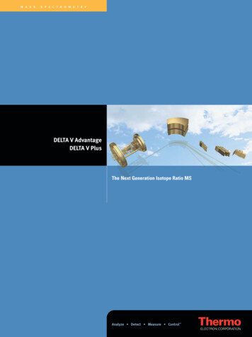
HIGH-PERFORMANCEDELTA-SIGMA ANALOG-TO-DIGITAL CONVERTERSCHAPTER 1. INTRODUCTIONHigh-performance delta-sigma analog-to-digital converters are desirable in applications where high resolutions (above 14 bits) and high bandwidths (several MHz) arerequired. This thesis describes the challenges and limitations associated with meetingthese requirements. It presents three techniques which can overcome those limitationsand provide considerable performance improvements even when low-quality analog components are used. These techniques, based on adaptive digital correction schemes andlow-distortion topologies, were combined in the implementation of a MASH ADC prototype chip, and verified to be highly effective.1.1.MotivationAnalog-to-digital converters (ADCs) are key components in applications where aninterface between the analog world and the increasingly digital signal processing worldis necessary. They can be found in an extensive range of devices in consumer, medical,communication and instrumentation applications, just to name a few.As illustrated in Fig. 1.1, a number of different ADC architectures is availablecovering a wide selection of bandwidth and resolution requirements. Each of these architectures uses a different method of operation which can be implemented efficiently fortheir optimum performance range.
2Resolution[bits] ,algorithmic10fl
Jos¶e Barreiro da Silva A THESIS submitted to Oregon State University in partial fulflllment of the requirements for the degree of Doctor of Philosophy Presented July 14, 2004 Commencement June 2005. ACKNOWLEDGMENTS I wish to express my deepest gratitude to my research advisors, Dr. G¶abor Temes