Transcription
Updated July 2022Pre-installation Checklist:VBX Series Load & GoPage 1 of 8www.automationwithinreach.com
VBX SeriesPRE-INSTALLATIONCNC CompatibilityThese CNC options are required for compatibility with the VBX Series Load & Go.FANUC1. Fanuc FOCAS 2 control version:a. Series 30i /31i /32i-MODEL Ab. Series 31i-MODEL A5c. Series 30i /31i /32i /35i-MODEL Bd. Series 31i-MODEL B5e. Power Motion i-MODEL Af. Series 0i-MODEL D/F2. Fanuc FAST Ethernet Option3. Automatic DoorHAAS1. Haas NGC next generation or legacy control, built after 2004.a. If a Haas Legacy control, add part #LG-VBX-LEGACY. No additional price.2. User-Definable Macros3. Automatic DoorOKUMA1. Okuma THINC API version 1.22 or later2. Automatic DoorIf Genos M460V-5AX3. Hydraulic fixture prep4. Vise manifold ATC door modification combo:a. 1-vise manifold ATC door, part #LG-M4605AX-ATC-1VISEb. 2-vise manifold ATC door, part #LG-M4605AX-ATC-2VISE 4,900 retail 4,900 retailIf Genos M460-VE3. ATC door modification, part #LG-VBX-M460-ATCD 990 retailHARDINGE, DMG MORI, DOOSAN, MAZAK With limitations, these CNC integrations are possible with a generic driver.The vise will stay clamped at a constant pressure once the machining program starts. Y and Zpush tools are not used. Running multiple part numbers is also handled with CNC programming.Page 2 of 8www.automationwithinreach.com
VBX SeriesPRE-INSTALLATIONPre-installation ChecklistWe made this list to help ensure successful automation and avoid common pitfalls. In our experience,customers run automated parts reliably when this checklist is followed.TimingInstallation will be scheduled by your local distributor after the below steps are completed, for a smooth install.If the customer responsibility steps are not completed when the service tech arrives, the install will berescheduled.AWR Responsibility1. Ensure that the customer is provided with this document containing correct VBX Series Load & Golocation as well as electrical and air requirements.2. Provide the customer with the date the machine will be shipped from the factory, the expected arrival dateat their facility and the planned installation date.3. Schedule an AWR authorized service technician to be on site for the duration of the installation and training.Customer ResponsibilityVBX Series1.2.3.4.Confirm floor-space for the VBX positioned in front and away from the CNC. [Page 4-7]Confirm floor-space for the PLC, usually on the right side of the CNC.[Page 5]Electrical power receptacle installed, 208-240VAC, 1-phase.[Page 7]Air supply tubing (0.5”) installed with 90-120psi.[Page 8]Part Process5. Install the vises with the manual control box.[Page 8]6. Machine the MultiGrip workholding and manually run parts.[Page 8]- This workholding design is critical. These parts will be tested during installation.Signature:Date:Contact AWR or your authorized dealer with any questions about these requirements.Page 3 of 8www.automationwithinreach.com
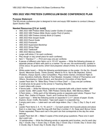
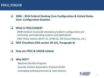
VBX SeriesPRE-INSTALLATIONVBX Series PlacementEnsure that there is adequate space in front of your CNC to pivot the VBX Series away. This allowsoperator access to the CNC. The following images show the VBX Series pivoted away and engaged withthe CNC.FIGURE 1. VBX Series PIVOTED FROM CNCPage 4 of 8www.automationwithinreach.com
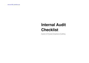
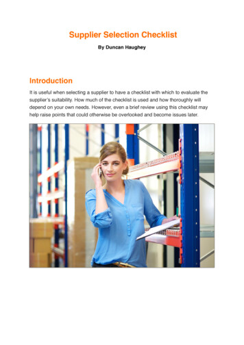
VBX SeriesPRE-INSTALLATIONRoute power and the air supplyline to the robot controller/ PLCarea. This is normally placed onthe right side of the CNC.240VAC, 1-phase0.5” air supply lineFIGURE 2. TOP VIEW OF VBX Series IN FRONT OF CNCUse caution when moving or pivoting the VBX Series. Risks to personnel may include severe bodily injury.Pay particular attention when pivoting the VBX Series to prevent pinching between the VBX Series, yourCNC machine, and other objects in the vicinity.FIGURE 3. TOP VIEW OF VBX Series PIVOTED AWAY FROM CNCPage 5 of 8www.automationwithinreach.com
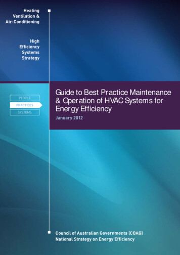
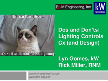
VBX SeriesPRE-INSTALLATIONGate and Pivot PostsGate and pivot posts are installed into the concrete in front of your CNC by AWR or an authorizeddealer/service provider. These posts maintain proper position of your VBX Series with respect to the CNC it istending. Four (4) holes are drilled into the concrete for each post, with 1/2” -13 UNC drop-in concrete anchorsinserted into the holes for attaching the posts to the floor.FIGURE 4 - GATE & PIVOT POSTSPage 6 of 8www.automationwithinreach.com
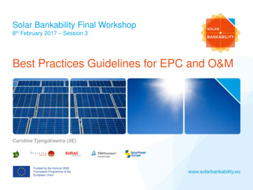
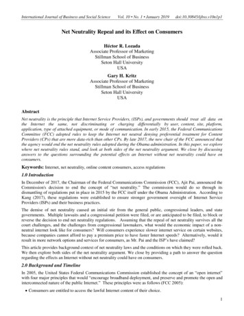
VBX Series Load & GoPRE-INSTALLATION GUIDEVBX Series Robot Controller PlacementThis robot controller/ PLC is 40” wide x 26” deep x 61” tall. It is typically located on the right side of the CNC,which gives it access to both the VBX Series cell and the CNC machine. It can be located less than 5 meters(16.4-feet) from the system.FIGURE 5. ROBOT CONTROLLER SHOWN ON BOTH SIDES OF CNCVBX Series Customer Electrical RequirementsThe electrical power supplied to the machine must comply with all local codes and ordinances.Electrical Supply to VBX Series:208-240VAC, 1-phase 50/60Hz 20A Max LoadRequired Electrical Service:1. Customer to provide electrical service via NEMAconnectors, twist lock style (see Figure 6).a. L1520R receptacle is required. 1- phase isused, although this receptacle is designed tohandle up to three phase.b. The VBX Series comes with Plug-L1520P.c. Distance: within 10 feet of VBX equipment2. Circuit breakers are UL489 compliant 20A, single phase3. Wire size for this electrical service should be AWG#10 or larger.Page 7 of 8FIGURE 6. POWER RECEPTACLE (L1520R)www.automationwithinreach.com
VBX Series Load & GoPRE-INSTALLATION GUIDECompressed Air Supply RequirementsThe VBX Series requires air supply at a minimum pressure and volume for proper operation. Theminimum requirements are:1. Minimum Flow Requirement: 8.8 cfm at 100psi (60 scfm)2. Air Pressure: 80-120psi3. Please provide the following air supply connection to the VBX Series: 1/2” diameter air supply tubing (forexample: McMaster-Carr #5648k33 orequivalent).VBX Series, PLC PanelIf you plan to use a quick coupler, use a1/2” coupler for the 1/2” air supply tubing.Vises and MultiGrip Workholding1. IMPORTANT: Review the MultiGrip workholding best practices found in the Machinist Manual(www.automationwithinreach.com/docs). Workholding designed for automation is critical for success.2. Position the vises in the front and center of the table to ensure robot reach. Reference the Vise TableConfigurations Manual, also on the website.3. To manually use the vises, a vise control box is provided. It can be located just outside the CNC to the right,or in some cases inside the CNC as shown. During installation, it will be connected to the VBX Series.Incoming airviseExample after installationAir to visesPage 8 of 8www.automationwithinreach.com
VBX Series Load & Go PRE-INSTALLATION GUIDE Page 7 of 8 www.automationwithinreach.com . It is typically located on the right side of the CNC, which gives it access to both the VBX Series cell and the CNC machine. It can be located less than 5 meters (16.4-feet) from the system. FIGURE 5. ROBOT CONTROLLER SHOWN ON BOTH SIDES OF CNC