Transcription
Journal of Automation and Control, 2013, Vol. 1, No. 1, 21-25Available online at http://pubs.sciepub.com/automation/1/1/4 Science and Education PublishingDOI:10.12691/automation-1-1-4Motion Analysis of In-pipe Robot Based on SMA SpringActuatorIvan Virgala*, Alexander Gmiterko, Michal KelemenDepartment of Applied Mechanics and Mechatronics, Faculty of Mechanical Engineering, Technical University of Košice, Košice,Slovakia*Corresponding author: ivan.virgala@tuke.skReceived May 06, 2013; Revised May 29, 2013; Accepted December 11, 2013Abstract The in-pipe robots play significant role for applications like inspection of pipes or wearing of cables andmaterials, etc. The paper deals with motion analysis of in-pipe robot, whose actuator is based on shape memoryeffect. At first, the principle of motion and design solution of experimental in-pipe robot is introduced. Then themathematical model is establish by means of Newton s mechanics. The robot using Baasic AtomPro 28-M iscontrolled in order to obtain autonomous of motion in the pipe. The robot can be used for pipes with circular sectionwith diameters 10-15 mm. For real behavior determination the experiments was done and compared withmathematical model. In the conclusion the advantages and disadvantages of in-pipe robot using SMA spring – steelspring actuator are discussed.Keywords: friction, pipe, SMA springCite This Article: Ivan Virgala, Alexander Gmiterko, and Michal Kelemen, “Motion Analysis of In-pipeRobot Based on SMA Spring Actuator.” Journal of Automation and Control 1, no. 1 (2013): 21-25. doi:10.12691/automation-1-1-4.1. IntroductionThere are several kinds of areas where the pipes areused which have to be researched or explored, for examplenuclear power plant, heat-exchanger, etc. Often theycannot be researched by man because of its dangerousenvironments and conditions or its unavailability. Hencethere should be used some kind of robot which is able tomoves through the pipe. In the paper the in-pipe robot willbe investigated, which is for small pipe diameter designed.There are a several issues what are under the researchconcerning in-pipe robots like difficult task to choosesuitable actuators, sensors, power supply, etc. [1] Thereare two basic approaches for robots motion design,namely wheeled and bristled locomotion [2,3]. Differentapproach is unconventional way of motion using severalSMA springs creating body in square shape according towork [4].In our study bristled in-pipe robot will be investigated.The bristled locomotion on the friction differences isbased. In other words, coefficient of friction is lower inthe forward direction in comparison with backwarddirection [5]. It can be reached by suitable design solutionof bristles [6,7]. As an actuator the SMA spring inconjunction with steel spring will be used. By SMA springdealt [11]. Next work [12] dealt with inchworm robotbased on SMA spring actuator. Based on mentioned worksour study was motivated.The paper is divided into following sections: At firstmechanical design of in-pipe robot consisting of SMA andsteel spring is introduced. Next section is dedicated to themathematical model of robot motion in the pipe. Fourthchapter deals with experimental analysis of SMA spring.In the fifth chapter the experiment with robot is done inorder to verification of locomotion with mathematicalmodel can be done. In the conclusion the advantages anddisadvantages of used in-pipe bristled robot are discussed.2. Mechanical Design of In-pipe RobotThere are several issues concerning the in-pipe robots.One of them is design of their actuator. In the past therewere investigated in-pipe robots with different actuatorslike geared DC motor, actuators based on magnetic fieldimpact, actuators based on SMA (shape memory alloy)wires, etc. [8,9,10].Figure 1. Heating and cooling of SMA springFor our study unconventional approach was chosen byusing actuator consisting of two subjects, namely SMAspring and steel spring. The actuator uses SME (shapememory effect) what means, that by heating of SMA
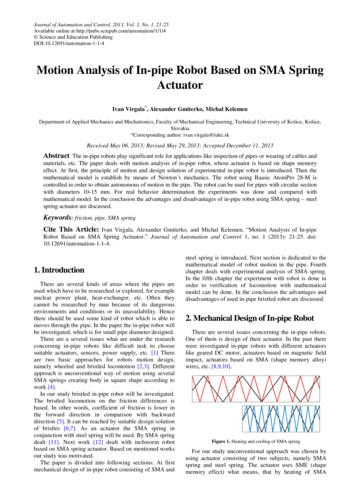
22Journal of Automation and Controlspring, the spring is widen. In the next phase the SMAspring is cooling and now it becomes shapeable. In thisphase the steel spring plays its role by shortening theSMA spring. So, by repeating of heating and cooling ofSMA spring we can reach forward motion of robot. Theprinciple of mentioned actuator in the Figure 1 is shown.The red color denotes heating phase of SMA spring andblue color denotes cooling phase of SMA spring.During the cooling phase the SMA spring can beshortened to 16 mm. During the heating phase the SMAcan be lengthened to 30 mm with over 4 N force. Insoftware SolidWorks 3D model of in-pipe robot wasdesigned, see Figure 2.The locomotion is divided into two phases. Thetraveled distance during one locomotion sequence is δ. Byrepeating of these two phases the robot performs forwardmotion through the pipe.3.1. First Phase of LocomotionDuring the first phase the second mass moves forwardbecause of difference of bristles friction. The first massmotion can be expressed by following equation.FS FfS FSMA 0(1)where Fs, Ffs and FSMA are force of steel spring, staticfriction and force of SMA spring, respectively. Staticfriction force isFfS µ S FNη(2)where μs is static friction coefficient and FN is load force.The symbol η represents function, described by 0 v 0 1 v 0 η Figure 2. CAD model of in-pipe robotIn-pipe robot has bristles with rectangular cross sectionwith length 2 cm and 1 mm thickness. The bristles arefrom flexible material in order to adaptability to the pipe.SMA spring is from material nitinol, which has shapememory effect.To ensuring that cooled SMA spring will movesforward not backward is achieved by bristles, attached tofront and back part of robot. As will be mentioned later,expected forward motion will be reached by difference offriction between forward and backward direction ofbristles.3. Mathematical Model of In-pipe RobotLocomotionThe mathematical model of bristled locomotion has itsfoundation in the nature. The model is inspired byearthworm or inchworm, which can move by means ofdifference of friction causes by bristles. The sequence ofmotion in the Figure 3 is shown.(3)The second mass motion can be expressed by followingequationFSMA FS Ff 0(4)where Fsma, FS and Ff are force of SMA spring, force ofsteel spring and friction force, respectively. Byconsideration of dry friction between in-pipe robot bristleand wall of pipe, the friction force by Coulomb frictioncan be represented, according equation (5).Ff µC FN sgn ( v )(5)where μc is Coulomb friction coefficient and FN is loadforce. Sgn(v) represents signum function, which can beexpressed by equation (6). 1 v 0 sgn ( v ) 0 v 0 1 v 0 (6)Coulomb friction force depends only on mass velocitydirection, not on velocity magnitude. From the equations(1) and (4) can be obtained terms for friction coefficients.µS FSMA FSwgη(7)µC FSMA FSwg sgn ( v )(8)where w is weight of in-pipe robot mass. It is obvious, thatthe higher difference between static and Coulomb frictioncoefficient is, the higher average velocity the robot canreaches. The difference between these two coefficients canbe reached by suitable design solution of bristles.3.2. Second Phase of LocomotionFigure 3. Sequence of in-pipe robot locomotionDuring the second phase of locomotion, the SMAspring is cooled. When SMA spring is cooled enough itloses its force and the steel spring starts pull the first massforward. The second phase can be described by similarway as first phase and friction coefficients are
Journal of Automation and ControlµC FSwg sgn ( v )(9)FSwgη(10)µS 3.3. Average Velocity of In-pipe RobotFor average velocity determination the duration of bothphases has to be expressed. Duration of the first phasefrom the motion equation (4) is derived by consideringinertia force on right side. Duration of the second phasefrom the equation of motion of the first mass is derived.Duration of the first phase ist1 2δ wFSMA FS µC wg sgn ( v )234.1. SMA Spring TestingFor testing of SMA spring the several steel linearsprings with different stiffness were used. The stiffness ofeach steel spring was determined and these springs wereused as opposite spring to the SMA spring in order toobtain a load for SMA spring. The voltage increasedgradually with step 0.2 V up to 2 V. The results ofmeasurements in the Figure 5 are shown.(11)Duration of second phase ist2 2δ wFS µC wg sgn ( v )(12)Now, average velocity can be expressed by followingtermvA δt1 t2(13)Consider that force of SMA spring is in the form of stepfunction. Then the theoretical average velocity dependingon changing force of SMA spring and changing Coulombfriction coefficient can be expressed by Figure 4.Figure 5. Displacement of SMA spring in dependence on voltage withdifferent load forcesAs can be in the Figure 5 seen, the higher load force is,the higher voltage (for higher value of current) isnecessary to reach full expansion of SMA spring. The loadforces were obtained from steel linear springs in such way,that steel spring were connected inside of SMA spring. Inother words, the steel spring pushed against SMA spring.The course of displacement is approximately linear. In thenext figure, the displacement in dependence on current isshown.Figure 6. Displacement of SMA spring with focus on current flowFigure 4. Theoretical average velocity of in-pipe robot4. Experimental Analysis of SMA Springand In-pipe Robot BristlesAs was mentioned above, the SMA spring changes itslength by means of two actions, namely heating andcooling. The heating phase is reached by connecting ofSMA spring ends to the voltage supply, what allows tocurrent flowing through the spring, whereby the springheats and its length expands. During the second phase thesupply of current is prevented and during this time theSMA spring cools and its length is shortened by affectingof steel spring.The current flowing through the SMA spring isrelatively high, over 4 A for 2 V. We can see that SMAspring is very demanding for current consumption what isineligible from the view of autonomous of system,because accumulators of small dimensions for this task areinapplicable.4.2. Friction Coefficient Measuring of In-pipeRobot BristlesFriction coefficient of in-pipe robot bristles plays verysignificant role for its locomotion through the pipe. Thelower Coulomb friction coefficient of bristle incomparison with static friction coefficient is, the highervelocity the robot will has. The basic assumption of robot
24Journal of Automation and Controlforward motion is that the friction coefficient in forwardmotion in lower that friction coefficient in backwardmotion.Friction coefficient in both direction by means oftribometer is determined, see Figure 7.the time which is significantly higher than the time whichwas considered in mathematical model. From the view ofmathematical model the average velocity of in-pipe robotcan be increased by suitable design solution of bristleswhat causes higher difference between static and Coulombfriction coefficient. In the reality this difference betweenthese two coefficients is not very significant, rathernegligible. This is caused because the time, necessary toheat the SMA spring and the time, necessary to cool, isvery high. For example, when the current flow to theSMA spring is prevented, it takes a significant time whileSMA spring cools and its force is lower in comparisonwith force of steel spring, which shortens SMA spring.Figure 7. Measuring of friction coefficientsUsing DC motor with screw the angle of inclinedsurface can be changed. Friction coefficient from the nextequations in obtained.Ff wg sin α 0(14)FN wg cos α 0(15)By next adjustment the static friction coefficient isexpressed by equation (16):µ S tgα(16)Tribometer is connected to the linear potentiometer invertical axis. The output from potentiometer through themeasuring I/O card MF624 is recorded in Matlab /Simulink which cooperates with measuring card by RealTime Toolbox. The output from Simulink is measuredcoefficient of friction. From measuring of frictioncoefficient was found thatµ Forward 0.449(17)µ Backward 0.589(18)Figure 8. In-pipe robot in the pipeConnection and disconnection SMA spring to thevoltage supply was automatized by means of 32-bitmicrocontroller Basic Atom Pro-28M. The problem withlong time for cooling was partly solved by blower, whichwas directed to the heated place. Because ofmicrocontroller dimensions, it could not be part of robotand it is placed out of the pipe.Next point of experimental part is investigation ofelectric power consumption by actuator SMA spring –steel spring. The electric current and electric powerconsumption by means of MF624 were measuredaccording to scheme, which in Matlab / Simulink wascreated. The example of measurement results in the Figure9 and Figure 10 are shown.From the Figure 9 and Figure 10 it can be seen, thatfirst phase of motion, when SMA spring is heated, lastroughly 40 seconds.Friction coefficient in forward direction is lower thanfriction coefficient in backward direction, whereby theforward motion is achieved. Friction coefficient inforward direction can of course be reduced by suitablemechanical modification according to user need.5. Experimental Analysis of In-pipeRobot LocomotionFor experiment the glass pipe with circular section withdiameter 13 mm is used. The first aim of experiment isfind out the differences between the real model andmathematical model. The second aim is analysis of powerconsumption which is necessary to robot locomotion. Thethird aim of experiment is to analyze SMA spring asactuator, its advantages and disadvantages for thesepurposes.In the third chapter was mentioned that one motioncycles consists of two phases. But difference between realand theoretical model is that SMA spring heats and coolsFigure 9. Course of electric current flowing through the in-pipe robotduring the first phase of motionIn the Figure 11 the legend shows the input voltage bywhich the recorded course of current was reached. As canbe seen in the Figure 11, the higher current input is, thelower time the first phase lasts. In other words, by highercurrent we can achieved faster heating of SMA spring andthen first phase duration lasts lower time. Nevertheless,the time of heating is still too high even if we use highervalue of current for heating. Given results are results thatwere obtained using blower for faster cooling phase.
Journal of Automation and Control25disadvantage of SMA spring is that it required highelectric power consumption, whereby classical batteryutilization becomes useless.In the future the SMA spring – steel spring actuatorshould be modified by suitable solution of SMA springcooling. For the tasks where does not matter on thevelocity of robot and application time this kind of robotcan be useful.AcknowledgementFigure 10. Electric power consumption necessary for SMA springextension during the first phase of motionThe authors would like to thank to Slovak GrantAgency – project VEGA 1/1205/12 “Numerical modelingof mechatronic systems”.References[1]Figure 11. First phase duration caused by different value of voltage input.The highest disadvantage of this kind of in-pipe robot isSMA spring heating and cooling phase which takes a lotof time what causes very slow locomotion, in our caseonly 2 mm/min.6. Conclusion and Future WorkIn the paper motion analysis of in-pipe robot moving inthe pipe with circular section with 13 mm diameter wasinvestigated. At first mechanical design of experimentalin-pipe robot is introduced. From the mathematical modelthe coefficients of friction in both directions are expressed.From the mathematical model the average velocity ofrobot motion in the pipe is expressed but this velocity isonly theoretical. The real average velocity is differentbecause SMA spring force increases and decreases slowly.In-pipe robot using actuator SMA spring – steel springhas advantages like very simple control, low weight, smalldimensions. In spite of these advantages its disadvantagesare very significant. One of the most disadvantage is theduration of heating and cooling phase. They can be a littlebit modified but this modification is highly limited.The system is autonomous in the straight pipes throughthe microcontroller Basic Atom Pro28-M. The nextGmiterko, A., Dovica, M., Kelemen, M., Fedák, V., Mlýnková, Z.,“In-pipe Bristled Micromachine”, IEEE 7th InternationalWorkshop on Advanced motion control, pp. 599-603, 2002.[2] Kelemenová, T., Kelemen, M., Miková, Ľ., Baláž, R., “BristledIn-pipe Machine Inside Pipe With Geometric Deviations”,Procedia Engineering – Elsevier / International Conference onModeling Mechanic and Mechatronic systems, pp. 287-294, 2012.[3] Tatar, O., Mandru, D., Ardelean, I., “Development of mobilenimirobots for in pipe inspection tasks”, Mechanika, pp. 60-64,Vol. 6 (68), 2007.[4] Iwashina, Sh., Hayashi, I., Iwatsuki, N., Nakamura, K.,“Development on In-Pipe Operation Micro Robots”, IEEE 5thInternational Symposium on Micro Machine and Human Science,pp. 41-45, 1994.[5] Wang, Z., “A Bristled-Based Pipeline Robot for I11-ConstraintPipes”, IEEE / ASME Transaction on Mechatronics, Vol. 13, No.3, June 2008.[6] Yu, H., Ma, P., Cao, Ch., “A Novel In-Pipe Worming RobotBased on SMA”, Proceedings of the IEEE InternationalConference on Mechatronics & Automation, pp. 923-927, NiagaraFalls, Canada, 2005.[7] Choi, H. R., Roh, S., “In-pipe Robot with Active SteeringCapability for Moving Inside of Pipelines”, Bioinspiration andRobotics: Walking and Climbing Robots, pp. 375-402, Austria2007.[8] Li, P., Ma, S., “Self-Rescue Mechanism for Screw Drive In-pipeRobots”, IEEE International Conference on Intelligent Robots andSystems, pp. 2843-2849, Taiwan 2010.[9] Yaguchi, H., Izumikawa, T., “Performance of Cableless MagneticIn-Piping Actuator Capable of High-Speed Movement by Meansof Inertial Force”, Advances in Mechanical Engineering, pp. 1-9,2001.[10] Yaguchi, H., Kamata, K., “In-piping Magnetic Actuator Capableof Inspection in a Thin Complex Pipe”, Mechanical EngineeringResearch, Vol. 2, No. 2, 2012.[11] Kim, S., Hawkes, E., Cho, K., Jolda, M., Foley, J., Wood, R.,“Micro artificial muscle fiber using NiTi spring for soft robotics”,IEEE International Conference on Intelligent Robots and Systems,pp. 2228-2234, USA, 2009.[12] Koh, J., Cho, K., “Omega-Shaped Inchworm-Inspired CrawlingRobot with Large-Index-and-Pitch (LIP) SMA Spring Actuators”,IEEE Transactions on Mechatronics, vol. 18, no. 2, 2013.
Ivan Virgala, Alexander Gmiterko, and Michal Kelemen, "Motion Analysis of In-pipe Robot Based on SMA Spring Actuator." Journal of Automation and Control. 1, no. 1 (2013): 21-25. doi: 10.12691/automation-1-1-4. 1. Introduction . software SolidWorks 3D model of in-pipe robot . was designed, see Figure 2. 00 Figure 2. CAD model of in-pipe robot
