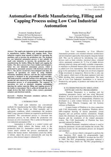
Transcription
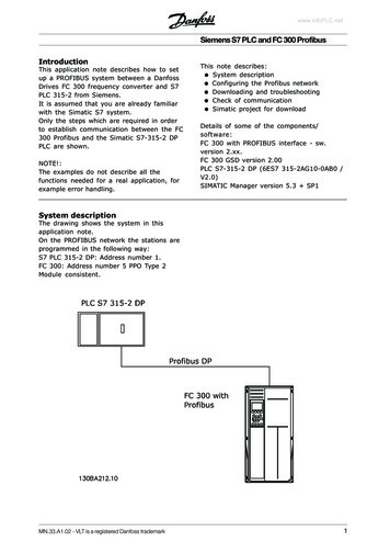
www.infoPLC.netSiemens S7 PLC and FC 300 ProfibusIntroductionThis application note describes how to setup a PROFIBUS system between a DanfossDrives FC 300 frequency converter and S7PLC 315-2 from Siemens.It is assumed that you are already familiarwith the Simatic S7 system.Only the steps which are required in orderto establish communication between the FC300 Profibus and the Simatic S7-315-2 DPPLC are shown.NOTE!:The examples do not describe all thefunctions needed for a real application, forexample error handling.This note describes:System descriptionConfiguring the Profibus networkDownloading and troubleshootingCheck of communicationSimatic project for downloadDetails of some of the components/software:FC 300 with PROFIBUS interface - sw.version 2.xx.FC 300 GSD version 2.00PLC S7-315-2 DP (6ES7 315-2AG10-0AB0 /V2.0)SIMATIC Manager version 5.3 SP1System descriptionThe drawing shows the system in thisapplication note.On the PROFIBUS network the stations areprogrammed in the following way:S7 PLC 315-2 DP: Address number 1.FC 300: Address number 5 PPO Type 2Module consistent.MN.33.A1.02 - VLT is a registered Danfoss trademark1
www.infoPLC.netSiemens S7 PLC and FC 300 ProfibusConfiguring the Profibus networkStart the SIMATIC Manager and create anew project.Open Hardware configuration in S7 Managerto configure the system.In order to configure a PROFIBUS system,the configuration tool needs a GSD file foreach type of slave on the network. TheGSD file is a PROFIBUS DP "standard" textfile containing the necessary communications setup data for a slave.Download the necessary GSD files ionsThe first step in configuration of thePROFIBUS Master is to import the GSD file inthe configuration tool. The steps outlinedbelow show how to add a new GSD file tothe Simatic Manager software tool. Foreach drive series, a GSD file is typicallyimported once only, following the initialinstallation of the software tool.Using the browser for the GSD file, chooseto install the needed GSD files. Both theGSD file and a bitmap for the device will beimported into the Hardware catalogue.2MN.33.A1.02 - VLT is a registered Danfoss trademark
www.infoPLC.netSiemens S7 PLC and FC 300 ProfibusConfiguring the Profibus networkThe GSD file is now imported and will beaccessible via the following path in theHardware catalogue.Note that the GSD revision should display arevision higher than 2.00.Insert a Profibus network and add aPROFIBUS Master system. Setup theProfibus network to a baud rate from 9.6kbaud to 12 Mbaud.Select FC 300 from the Hardware catalogueand drag and drop it to the PROFIBUSnetwork.A window for the address of the FC 300now appears. Select the address from thescroll-down list. Note that this addresssetting must match the address setting inpar. 9-18 Node address.MN.33.A1.02 - VLT is a registered Danfoss trademark3
www.infoPLC.netSiemens S7 PLC and FC 300 ProfibusConfiguring the Profibus networkThe next step is to set up the peripheralinput and output data via a PPO type. Inthe peripheral area data is transmittedcyclically via PPO types. In the examplebelow, a PPO type 2 Module consistent isdragged and dropped to the first slot.The choice of PPO type is made in themaster configuration, and is then automatically recorded in the frequency converter.No manual setting of PPO types in the FC300 is required.The current PPO type can be read in par.9-22 Telegram selection.4In addition, all PPO types can be set up asword consistent or module consistent.For FC 300, the process data area can beword or module consistent, whereas theparameter channel must always be moduleconsistent. Module consistent data istransmitted as sets of interrelated wordstransferred simultaneously between the PLCprogram and the Profibus master. Wordconsistent data is transmitted as individualindependent words between the PLC andthe Profibus master.MN.33.A1.02 - VLT is a registered Danfoss trademark
www.infoPLC.netSiemens S7 PLC and FC 300 ProfibusConfiguring the Profibus networkThe system is now set up to use the PPOtype 2 in the following peripheral I/O area:Parameter Characteristic (PCA), i.e. readand write to parameters.Parameter channel Parameter channel Process data, i.e. write a Control word andReference and receiving a Status word andMain Actual Value.Master to SlaveProcess channel (PCD)PCD 1PCD 2ControlReferencewordPQW 264 PQW 266Slave to MasterProcess channel (PCD)PCD 1PCD 2StatusMain ActualwordValuePIW 264PIW 266PCD 3TorquelimitPQW 268PCD 3MotorcurrentPIW268PCD 4Ramp 1up timePQW270PCD 4FrequencyPIW 270PCD 5EmptyPCD 6EmptyPQW272PQW274PCD 5DigitalinputPIW272PCD 6EmptyPIW274PQW means the data from the Master tothe Slave. By PCA the output data willcontain the request of a parameter read orwrite. By Process data the first word ofoutput data is the Control word of the FC300 and the next is the Reference. The restof the words can be freely configured totransmit different kind of data to the FC300 in parameter 915 PCD Write Configuration.PIW means the data from the Slave to theMaster. By PCA the input data will containthe response of a parameter read or write.By Process data the first word of input datais the Status word of the FC 300 and thenext is the Main Actual Value. The rest ofthe words can be freely configured totransmit different kind of process data inparameter 916 PCD Read Configuration. Seeexample on next page.MN.33.A1.02 - VLT is a registered Danfoss trademark5
www.infoPLC.netSiemens S7 PLC and FC 300 ProfibusConfiguring the Profibus networkNormally the setup of the PCD area is donein parameter 915 PCD Write Configurationand 916 PCD Read Configuration via the LCPor the MCT 10 Setup Software. In FC 300 itis possible to automatic configure the PCDarea in the PLC via the GSD file in SimaticManager. The configuration of parameter915 and 916 is done when either the PLC orthe VLT is being power up via theparameterise telegram.Note that to configure the PCD area via thePLC the FC 300 and the GSD file need tohave a software version higher than 2.00.Double click on the FC 300 and the click onParameter assignment:By Device-specific parameters it is possibleto use the Scroll down list to setup the PCDarea. Remember to chose "EnableAutoconfig" for automatic configuration ofPCD data.P915/0 to P915/9 is process data writtenfrom the PLC to the FC 300, PQW area.P916/0 to P916/9 process data from the FC300 to the PLC, PIW area.6MN.33.A1.02 - VLT is a registered Danfoss trademark
www.infoPLC.netSiemens S7 PLC and FC 300 ProfibusConfiguring the Profibus networkThe Parameter channel can only be accessas consistent data and there for SystemFunction Call (SFC) are needed. In Simaticyou should use SFC 14 for reading data andSFC 15 for writing data.The Process channel can be access asmodule or word consistent. In this examplemodule consistent is used and thereforeagain SFC 14 / 15 is needed.If a PPO type 2 Word consistent waschosen the peripheral I/O area can beaccess in each word.MN.33.A1.02 - VLT is a registered Danfoss trademark7
www.infoPLC.netSiemens S7 PLC and FC 300 ProfibusDownloading and troubleshootingSet the PLC in stop with the key on the PLCprocessor and download the program.Note that the FC 300 will show a Fieldbusfault while the PLC is in Stop mode.Before the PLC can be set in RUN modeensure that the node address in par. 918match the corresponding address in theprogram. Note that a change of parameter918 is first active at next power up.After the download of the PLC program theLED marked as "NS" on the Profibus cardshould be solid green when the key on theS7 master is set in RUN. This indicate thatthe master and slave is communicating.The LED marked "MS" indicates the modulestatus, i.e. acyclical DP V1 communicationfrom either a PROFIBUS master class 1(PLC) or a master class 2 (MCT 10, FDTtool). When this light shows constantgreen, then DP V1 communication frommaster classes 1 and 2 is active.If the "NS" LED on the FC 300 Profibus cardisn't solid green the fault could be:- Wrong address setting in parameter 918Node address according to the master.- After changing the parameter 918 Nodeaddress the power hasn’t been cycle.- Wrong cable connection, check the cableby the master and the FC 300.62 RxD/TxD-P Red cable63 RxD/TxD-N Green cable- The termination of the Profibus networkisn't correct done.- Wrong GSD file. Check that the used GSDfile is for FC 300.See the FC 300 Profibus OperatingInstruction for a more comprehensivetroubleshooting.Check of the communicationTo easily check the communication betweena Master and the FC 300 in the SimaticManager a Variable Table (VAT) can becreated.Go to S7 Programs and Blocks and create aVAT table.8MN.33.A1.02 - VLT is a registered Danfoss trademark
www.infoPLC.netSiemens S7 PLC and FC 300 ProfibusCheck of the communicationOpen the VAT table and insert a range ofvariable from PIW 256 of 10 words andrange of variable from PQW 256 of 10words.Now the peripheral input data from PIW256 – 274 can be monitored by clicking onthe glasses.In this example the peripheral input data willshow the following:- PIW 256 shows the PCA response of aparameter transfer double word(parameter 351).- PIW 262 shows the data of parameter351 (300)- PIW 264 shows the FC 300 Status word- PIW 266 shows the Main actual Value- PIW 268 shows the actual Motor current(1.55 Amp)- PIW 270 shows the frequency (12.6 Hz)- PIW 272 shows the status of the digitalinputs (terminal 19 1)MN.33.A1.02 - VLT is a registered Danfoss trademark9
www.infoPLC.netSiemens S7 PLC and FC 300 ProfibusSimatic projectA Simatic project is available fordownloading on ns. This projectcontains a Function Block 50 which can beused to parameterise and control a FC 300via PP0 type 2 Module consistent. Downloadthe zip file ?.10MN.33.A1.02 - VLT is a registered Danfoss trademark
area in the PLC via the GSD file in Simatic Manager. The configuration of parameter 915 and 916 is done when either the PLC or the VLT is being power up via the parameterise telegram. Note that to configure the PCD area via the PLC the FC 300 and the GSD file need to have a software version higher than 2.00. Double click on the FC 300 and the .